
HEAT EXCHANGER DESIGN
• Aluminized steel primary heat exchanger with crimped non-
welded construction
• AL29-4C Stainless steel secondary heat exchanger
• Non-welded crimped S-curve primary heat exchanger design
for maximum durability
BURNERS
• Aluminized steel in shot burners for smooth ignition
• Isolated burner enclosure for quiet operation
CABINET CONSTRUCTION
• Compact 33" height
• Standardized widths for easy coil fit
• Unitized construction for cabinet integrity
• Heat exchanger compartment is insulated to increase
efficiency and reduce sound levels
• Baked on pre painted steel cabinet finish
AIR DELIVERY SYSTEM
• Efficient ECM variable speed blower motor
• Motor features "soft start" and "soft stop" for quiet operation
• Active and passive dehumidification feature
• Easily removable slide-out blower design
• Dynamically balanced blower wheel with resilient
motor mounts for smooth and quiet operation
CONTROLS
• Two stage gas valve
• Integrated ignition and fan control
• System Sentry™ control retains last five (5) fault codes with
push button memory recall, regardless of power interruption
• Hot surface ignition system uses silicon nitride ignitor
• Control features 120 volt electronic air cleaner and humidifier
terminals
• Control circuit is fuse protected
• Color coded control wiring
• Compatible with single or two stage thermostats for heating.
• Two stage thermostat is recommended when installed with
two stage cooling unit.
WARRANTY
10 year limited parts warranty / lifetime heat exchanger warranty
available. See limited warranty document for details.
California Only
If installed in South Coast Air Quality Management District (SCAQMD) only: This
furnace does not meet the SCAQMD Rule 1111 NOx emission limit (14 ng/J), and
thus is subject to a mitigation fee of up to $450. This furnace is not eligible for the
Clean Air Furnace Rebate Program: www.CleanAirFurnaceRebate.com.
If installed in San Joaquin Valley Air Pollution Control District (SJVAPCD) only:
This furnace does not meet the SJVAPCD Rule 4905 NOx emission limit (14 ng/J),
and thus is subject to a mitigation fee of up to $450.
CONFIGURATIONS
• Upflow / Horizontal
• Downflow
VENTING
• 2-speed induced draft motor with stainless steel shaft, steel ball
bearings, and fan cooled for long life
• Vent materials for Canadian applications must comply with ULC S636
• Certified for direct vent (2-pipe) or non-direct (1-pipe) applications
• Direct vent refers to a combustion air supply intake pipe installed in
conjunction with flue gas vent pipe.
INSTALLATION FEATURES
• Left or right gas and electric entry
• Zero step horizontal conversion
• Removable floor base (upflow/horizontal units) for bottom return air
• All models comply with California's South Coast Air Quality
Management district Low NOx requirements
96G2V
PRODUCT SPECIFICATIONS
TWO STAGE VARIABLE SPEED
GAS FURNACE
FORM NO. 96G2V-100 (08/2019)
Page 1

96% GAS FURNACE 96G2V
Page 2
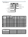
MODEL NUMBER GUIDE
PHYSICAL AND ELECTRICAL DATA
MODEL
1ST STAGE 2ND STAGE
AFUE
(ICUS)
NOM.
COOLING
CAPACITY
(TONS)
GAS
INLET
(IN.)
VOLTS/
HZ/
PHASE
MIN.
TIME
DELAY
BREAKER
OR FUSE
NOMINAL
F.L.A.
TRANS.
(V.A.)
APPROX.
WEIGHT
(LBS.)
INPUT
(BTUH)
OUTPUT
(BTUH)
INPUT
(BTUH)
OUTPUT
(BTUH)
UPFLOW/HORIZONTAL
96G2UH045BV12 29,000 28,000 44,000 42,000 96.0 3 1/2 120-60-1 15 7.7 40 130
96G2UH070BV12 43,000 41,000 66,000 62,000 96.0 3 1/2 120-60-1 15 7.7 40 138
96G2UH090CV12 57,000 55,000 88,000 84,000 96.0 3 1/2 120-60-1 15 7.7 40 154
96G2UH090CV20 57,000 55,000 88,000 85,000 96.0 5 1/2 120-60-1 20 12.8 40 166
96G2UH110CV20 72,000 70,000 110,000 105,000 96.0 4 1/2 120-60-1 15 12.8 40 173
96G2UH135DV20 88,000 84,000 132,000 126,000 96.0 5 1/2 120-60-1 20 12.8 40 188
DOWNFLOW
96G2DF070BV16 43,000 42,000 66,000 64,000 96.0 4 1/2 120-60-1 15 10.1 40 136
96G2DF090CV20 57,000 56,000 88,000 85,000 96.0 5 1/2 120-60-1 20 12.8 40 164
96G2DF110CV20 72,000 70,000 110,000 106,000 96.0 5 1/2 120-60-1 20 12.8 40 176
Note: For vent length and clearances to combustibles, please reference installation instructions.
Airflow
Descriptor
Disposable Filters Cleanable Filters
Minimum Area
(sq. in.)
Minimum Area
(sq.in.)
12 576 288
16 768 384
20 960 480
FILTER REQUIREMENT DATA
1. The Airflow Descriptor is the two digits following the "B", "C", or "D" in the model number; e.g. "20" is the Airflow Descriptor.
2. Areas shown for permanent filters are based on filters rated at 600 feet per minute face velocity.
NUMERIC CODE
REVISION CODE
NOM. CFM X 00
12 = 3 TON ADD ON COOLING
16 = 4 TON ADD ON COOLING
20 = 5 TON A DD ON COOLING
BLOWER DRIVE
V = VARIABLE SPEED
AFUE
96 = 96% EFFICENCY
GAS
STAG ES
2 = TWO STAGE
CONFIGURATION
UH = UPFLOW/HORIZONTAL
DF = DOWNFLOW
BTUH INPUT
HEATING INPUT X 1000
CABINET WIDTH
B = 17.5” WIDTH
C = 21.0” WIDTH
D = 24.5” WIDTH
96 G 2 UH 110 C V 16 -01

96% GAS FURNACE 96G2V
Page 3
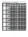
BLOWER PERFORMANCE DATA (UPFLOW / HORIZONTAL)
MODEL
MOTOR
SIZE (HP)
BLOWER
SIZE
HEATING
TEMP.
RISE
(°F)
HEATING CFM @ .10" - .80" W.C.
COOLING
STAGE
COOLING CFM @ .10" - .80" W.C.
SPEED
ADJUST.
SETTING
"D"
SETTING
"C"
SETTING
"B"
SETTING
"A"
SETTING
"D"
SETTING
"C"
SETTING
“B”
SETTING
"A"
UPFLOW / HORIZONTAL
96G2UH045BV12
1/2 10x9
35-65
High
Fire
745 875 990 1005
2nd
Stage
905 1075 1210 1370 +
685 765 895 910 815 980 1120 1255 Norm
610 695 785 810 720 885 1020 1135 -
20-50
Low
Fire
685 765 895 910
1st
Stage
595 760 865 980 +
620 705 800 820 540 660 785 890 Norm
545 625 715 725 485 600 695 790 -
96G2UH070BV12
1/2 10x9
50-80
High
Fire
965 1060 1130 1255
2nd
Stage
860 1060 1215 1365 +
880 960 990 1140 810 960 1130 1265 Norm
810 840 890 1030 705 840 1005 1140 -
25-55
Low
Fire
940 990 1070 1195
1st
Stage
600 740 840 970 +
830 895 965 1100 555 665 770 855 Norm
755 825 840 975 500 600 680 790 -
96G2UH090CV12
1/2 10x9
60-90
High
Fire
1060 1135 1240 1315
2nd
Stage
875 1040 1210 1360 +
960 1040 1120 1199 800 945 1100 1245 Norm
830 935 980 1084 720 840 970 1115 -
30-60
Low
Fire
960 1040 1120 1206
1st
Stage
625 710 830 950 +
875 945 995 1100 565 670 760 860 Norm
790 840 920 950 520 610 685 785 -
96G2UH090CV20
1 11x11
40-70
High
Fire
1450 1565 1725 1865
2nd
Stage
1385 1595 1820 2020 +
1310 1450 1585 1690 1225 1465 1645 1885 Norm
1155 1305 1450 1545 1065 1320 1504 1675 -
25-55
Low
Fire
1120 1265 1420 1520
1st
Stage
935 1055 1275 1465 +
965 1120 1285 1395 835 980 1120 1335 Norm
865 950 1120 1235 740 870 1010 1150 -
96G2UH110CV20 1 11x11
45-75
High
Fire
1560 1760 1905 1955
2nd
Stage
1310 1560 1745 1955 +
1415 1610 1740 1795 1220 1405 1570 1795 Norm
1285 1485 1560 1635 1075 1270 1430 1635 -
35-65
Low
Fire
1155 1325 1420 1500
1st
Stage
935 1065 1245 1405 +
1055 1200 1310 1360 865 970 1145 1280 Norm
935 1075 1170 1245
790 890 1025 1165 -
96G2UH135DV20 1 11x11
45-75
High
Fire
1650 1845 2000 2055
2nd
Stage
1395 1640 1840 2055 +
1495 1660 1880 1905 1290 1480 1660 1905 Norm
1360 1500 1670 1705 1170 1330 1500 1705 -
35-65
Low
Fire
1300 1435 1630 1652
1st
Stage
1015 1160 1330 1480 +
1190 1325 1465 1491 940 1085 1200 1345 Norm
1095 1190 1340 1343 870 965 1110 1225 -

96% GAS FURNACE 96G2V
Page 4
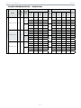
BLOWER PERFORMANCE DATA (DOWNFLOW)
MODEL
MOTOR
SIZE (HP)
BLOWER
SIZE
HEATING
TEMP.
RISE
(°F)
HEATING CFM @ .10" - .80" W.C.
COOLING
STAGE
COOLING CFM @ .10" - .80" W.C.
SPEED
ADJUST.
SETTING
"D"
SETTING
"C"
SETTING
"B"
SETTING
"A"
SETTING
"D"
SETTING
"C"
SETTING
“B”
SETTING
"A"
DOWNFLOW
96G2DF070BV16 3/4 11x10
35-65
High
Fire
1110 1305 1430 1700
2nd
Stage
1110 1340 1575 1800 +
995 1175 1315 1520 995 1230 1420 1650 Norm
880 1055 1170 1365 880 1085 1290 1460 -
25-55
Low
Fire
860 1020 1140 1340
1st
Stage
740 915 1055 1255 +
795 910 1030 1230 660 820 940 1120 Norm
680 825 910 1085 575 735 850 995 -
96G2DF090CV20 1 11x11
40-70
High
Fire
1395 1555 1695 1825
2nd
Stage
1335 1600 1750 1980 +
1275 1395 1585 1670 1225 1450 1630 1830 Norm
1145 1265 1405 1525 1120 1270 1450 1660 -
30-60
Low
Fire
1130 1230 1365 1475
1st
Stage
955 1115 1265 1450 +
1040 1130 1250 1340 855 1005 1150 1285 Norm
910 1025 1130 1210 750 890 1060 1170 -
96G2DF110CV20 1 11x11
45-75
High
Fire
1595 1795 1955 2010
2nd
Stage
1335 1585 1790 2010 +
1450 1615 1795 1865 1220 1440 1630 1865 Norm
1290 1460 1610 1680 1100 1275 1475 1680 -
35-65
Low
Fire
1165 1305 1465 1547
1st
Stage
920 1095 1265 1440 +
1055 1185 1315 1404 830 965 1130 1290 Norm
930 1070 1180 1272 735 860 1035 1155 -

96% GAS FURNACE 96G2V
Page 5
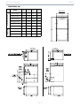
Front View
DIMENSIONS (IN.)
MODEL A B C D
UPFLOW/HORIZONTAL
96G2UH045BV12 17-1/2 16-3/8 16 7-5/8
96G2UH070BV12 17-1/2 16-3/8 16 7-5/8
96G2UH090CV12 21 19-7/8 19-1/2 9-3/8
96G2UH090CV20 21 19-7/8 19-1/2 9-3/8
96G2UH110CV20 21 19-7/8 19-1/2 9-3/8
96G2UH135DV20 24-1/2 23-3/8 23 11-1/8
DOWNFLOW
96G2DF070BV16 17-1/2 16-3/8 16 15-1/2
96G2DF090CV20 21 19-7/8 19-1/2 19
96G2DF110CV20 21 19-7/8 19-1/2 19

96% GAS FURNACE 96G2V
FORM NO. 96G2V-100 (08/2019) Printed in the U.S.A.© 2019 Allied Air Enterprises LLC, a Lennox International Inc. Company
1-800-448-5872
All specifications and illustrations
subject to change without notice and
without incurring obligations.
Page 6
ACCESSORY LIST
CATALOG NUMBER DESCRIPTION
EXTERNAL FILTER RACK KITS
1.841018 1 PACK (16 X 25)
1.841039 10 PACK (16 X 25)
NATURAL TO LP KITS
11K48 2-STAGE - 90
11K47 HIGH ALTITUDE 2-STAGE (>4500FT.)
RETURN AIR BASE
68W62 17.5" B WIDTH
68W63 21.0" C WIDTH
68W64 24.5" D WIDTH
DOWNFLOW COMBUSTIBLE FLOORING BASE
11M60 17.5" B WIDTH
11M61 21.0" C WIDTH
NIGHT SERVICE KITS
84W50 TWO STAGE
HORIZONTAL SUSPENSION KIT
51W10 80% & 90% KIT
FLUSH MOUNT TERMINATION (90% FURNACES ONLY) US ONLY
51W11 2" & 3" VENT VERSION
CONCENTRIC VENT KIT (90% FURNACES ONLY) US ONLY
71M80 1-1/2" VENT VERSION
69M29 2" VENT VERSION
60L46 3" VENT VERSION
CONCENTRIC VENT KIT (90% FURNACES ONLY) CANADA
44W92 1-1/2" AND 2" VENT VERSION
44W93 3" VENT VERSION
For vent length and clearances to combustibles, please reference installation instructions.
-
 1
1
-
 2
2
-
 3
3
-
 4
4
-
 5
5
-
 6
6


in anderen Sprachen
- English: ROYALTON 96G2DF110CV20 Specification
Sonstige Unterlagen
-
Lochinvar PB-1501(M9) Benutzerhandbuch
-
-
-
-
Bauer Jupiter 250 Mounting instructions
-
GGM Gastro KFTPO118SN-BW Bedienungsanleitung
-
Liebherr EFE 5100 Bedienungsanleitung
-
Thomson ACR 4251 Bedienungsanleitung
-
STIEBEL ELTRON AUK 7-35 Operation Instruction
-
Yamaha MOTIF-RACK ES Datenblatt