

CAUTION
1 To assure the finest performance, please read this manual
carefully. Keep it in a safe place for future reference.
2 Install the speakers in a cool, dry, clean place – away from
windows, sources of heat, sources of excessive vibration, dust,
moisture or cold. Avoid sources of electrical humming (e.g.,
transformers and motors). To prevent fire or electric shock, do not
expose the speakers to rain or water.
3 To prevent the enclosure from warping or discoloring, do not
expose the speakers to direct sunlight or excessive humidity.
4 Avoid installing the speakers where foreign objects may fall onto
them and/or where they may be exposed to liquid dripping or
splashing.
5 Do not place the following objects on top of the speakers:
– Other components, as they might damage or discolor the
surface of the speakers;
– Burning objects (e.g., candles), as they might cause fire,
damage to the speakers or personal injury;
– Containers of liquid, as they might spill and cause electric
shock to the user or damage to the speakers.
6 Do not place the speakers where they are liable to be knocked
over or struck by falling objects. Stable placement will also
ensure better sound.
7 Placing the speakers on the same shelf or rack as the turntable
can result in feedback.
8 Secure placement or installation is the owner’s responsibility.
YAMAHA is not liable for accidents caused by improper
placement or installation of speakers.
9 If you note distortion, reduce the volume control on your
amplifier. Do not drive your amplifier to the point of “clipping”.
Otherwise, the speakers may be damaged.
10 When using an amplifier with a rated output power higher than
the nominal input power of the speakers, care should be taken not
to exceed the speakers’ maximum input.
11 Do not clean the speakers with chemical solvents as this might
damage the finish. Use a clean, dry cloth.
12 Do not attempt to modify or fix the speakers. Contact qualified
YAMAHA service personnel when service is needed. Do not
open the cabinet under any circumstances.
13 Please read the “Troubleshooting” section regarding common
operating errors before concluding that the speakers are faulty.
For the SW-P330
1 Do not operate this unit upside down. It may overheat, possibly
causing damage.
2 Do not use excessive force on switches, controls or connection
wires. When moving this unit, first disconnect the power plug
and the wires connected to other equipment. Never pull the wires
themselves.
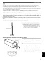
3 Since this unit has a built-in power amplifier, heat radiates from
the rear panel. Place the unit away from walls, allowing at least
20 cm of space above, behind and on both sides of the unit to
prevent fire or damage. Furthermore, do not position the unit with
the rear panel facing down on the floor or other surfaces.
4 When using a humidifier, be sure to avoid condensation inside
this unit by allowing enough space around the unit and avoiding
excess humidification. Condensation might cause fire, damage to
the unit, or electric shock.
5 Do not cover the rear panel of this unit with a newspaper,
tablecloth, curtain, etc. to avoid obstructing heat radiation. If the
temperature inside the unit rises, it may cause fire, damage to the
unit, or personal injury.
6 Do not plug this unit into a wall outlet until all connections are
complete.
7 The voltage to be used must match that specified on the rear
panel. Using this unit with a voltage higher than specified is
dangerous and may cause fire, damage to the unit, or personal
injury. YAMAHA is not responsible for damage resulting from
use of this unit with a voltage other than specified.
8 To prevent damage from lightning, disconnect the AC power plug
during electric storms.
9 Super-bass frequencies reproduced by this unit may cause a
turntable to generate audio feedback. In this case, move the unit
away from the turntable.
10 This unit may be damaged if certain sounds are continuously
output at high volume level. For example, if 20Hz–50Hz sine
waves from a test disc or bass sounds from an electronic
instrument, etc. are continuously output, or if a turntable stylus
touches the surface of a disc, reduce the volume level to prevent
the unit from being damaged.
11 If you hear distorted noise (i.e., unnatural, intermittent “rapping”
or “hammering” sounds) from this unit, reduce the volume level.
Extremely loud movie soundtrack low frequency, bass-heavy
sounds, or similarly loud popular music passages can damage the
speaker system.
12 Vibration generated by super-bass frequencies may distort
images on a TV. In this case, move the unit away from the TV set.
13 When disconnecting the power cord from the wall outlet, grasp
the plug; do not pull the cord.
14 When you plan not to use this unit for a long period of time (i.e.,
vacation, etc.) disconnect the AC power plug from the wall
outlet.
15 Do not place much pressure against the subwoofer net. It may
break the net or the unit may fall, resulting in injury.
16 Do not place anything fragile beside the subwoofer. The air
pressure produced by the subwoofer may break the objects and
cause malfunction or injury.
FOR CANADIAN CUSTOMERS
To prevent electric shock, match wide blade of plug to wide
slot and fully insert.
This Class B digital apparatus complies with Canadian
ICES-003.
WARNING
TO REDUCE THE RISK OF FIRE OR ELECTRIC SHOCK,
DO NOT EXPOSE THIS APPLIANCE TO RAIN OR MOIS-
TURE.
IMPORTANT
Please record the serial number of this unit in the space below.
MODEL:
Serial No.:
The serial number is located on the rear or the bottom of this
unit.
Retain this Owner’s Manual in a safe place for future
reference.
CAUTION: READ THIS BEFORE OPERATING YOUR UNIT.

1
English
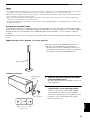
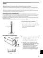
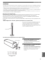
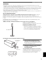
This product is a speaker package consisting of the components
shown on the table.
Please check to make sure that all of the components listed in the
table are included.
Active Servo Processing Subwoofer System with built-in
power amplifier.
This subwoofer system (SW-P330) employes Advanced
YAMAHA Active Servo Technology which YAMAHA has
developed for reproducing higher quality super-bass sound.
This super-bass sound adds a more realistic, theater-in-the-
home effect to your stereo syetem.
■ For U.K. customers
If the socket outlets in the home are not suitable for the plug
supplied with this appliance, it should be cut off and an
appropriate 3 pin plug fitted. For details, refer to the instructions
described below.
The plug severed from the mains lead must be destroyed, as a
plug with bared flexible cord is hazardous if engaged in a live
socket outlet.
■ Special Instructions for U.K. Model
IMPORTANT
THE WIRES IN MAINS LEAD ARE COLOURED IN
ACCORDANCE WITH THE FOLLOWING CODE:
Blue: NEUTRAL
Brown: LIVE
As the colours of the wires in the mains lead of this apparatus
may not correspond with the coloured markings identifying
the terminals in your plug, proceed as follows:
The wire which is coloured BLUE must be connected to the
terminal which is marked with the letter N or coloured
BLACK. The wire which is coloured BROWN must be
connected to the terminal which is marked with the letter L or
coloured RED.
Making sure that neither core is connected to the earth
terminal of the three pin plug.
Introduction.................................................... 2
About this manual .....................................................2
Package Contents.......................................... 2
Roles and Layout of Speakers ..................... 3
Placing the Speakers..................................... 3
Placing the center speaker.........................................3
Placing the subwoofer...............................................4
Placing the front and surround speakers ...................4
Connecting the speakers............................................6
Connecting speaker cables........................................7
Using the subwoofer (SW-P330) ..............................8
Advanced Yamaha Active Servo Technology
(on the SW-P330)..................................................9
Troubleshooting .......................................... 10
Specifications .............................................. 11
Model name Category No. of pcs
NS-P330
NX-S200
Satellite speakers
(for front/surround)
4
NX-C200 Center speaker 1
SW-P330 Subwoofer 1
NS-P336
NX-S200
Satellite speakers
(for front/surround)
5
NX-C200 Center speaker 1
SW-P330 Subwoofer 1
Note
Table of Contents

INTRODUCTION
2
“NS-P330/NS-P336” consists of four/five satellite speakers (front/surround), a center speaker, and a subwoofer. Please
take great pleasure in real sounds with the YAMAHA 5.1ch/6.1ch speaker system “NS-P330/NS-P336”.
• This manual provides only information on installation methods or specifications for the speakers. For information about
how to connect the speakers to your YAMAHA amplifier, refer to the manual for amplifier.
• This manual was printed before final product development. Due to operational upgrades and other reasons, the
specifications of the actual product or packaging may differ from the contents of this manual.
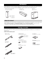
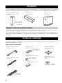
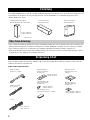
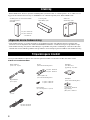
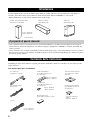
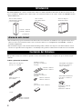
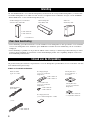
This product includes the following items. Before installing the speakers, please check that you received all of the
following parts.
Cables and installation parts
Introduction
Satellite speakers (front/surround/
surround back
*
) NX-S200
Center speaker
NX-C200 (1 unit)
Subwoofer
SW-P330 (1 unit)
*
for NS-P336
4 units : NS-P330
5 units : NS-P336
About this manual
Package Contents
Subwoofer cable
(1 pin, 5 m, 1 unit)
Screws (M4 × 10)
(for front/surround speakers)
Speaker Cables
(4 m/3 units)
Non-skid pads
(for subwoofer, 1 set: 4 units)
Fasteners
(for center speaker, 2 units)
Non-skid pads
(for front/surround speakers)
Mounting brackets
(for front/surround speakers)
(15 m)
2 units : NS-P330
3 units : NS-P336
4 units : NS-P330
5 units : NS-P336
4 units : NS-P330
5 units : NS-P336
4 sets (16 units) : NS-P330
5 sets (20 units) : NS-P336

3
English
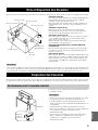
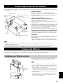
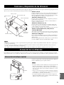
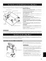
Each speaker has different roles based on the types of sound each produces. This section explains the main role/s of each speaker and the
recommended speaker layout.
Center Speaker
Place on top of the TV or inside the TV rack so that the speaker
and TV are aligned vertically.
Main role: Produces sounds oriented toward the center of the
screen such as dialogues or vocal sounds.
Front Speakers (L, R)
Place the front left/right speakers on both sides of your TV at
equal distances.
Main roles: Produces front channel (stereo) sounds and effect
sounds.
Surround Speakers (L, R)
Place the surround left/right speakers behind the listening
position. (We recommend placing them at a height of 1.8 m
(6 feet) and pointing them at the listening position.)
Main roles: Produces surround sounds and effect sounds.
Surround back speaker (for NS-P336 systems
only)
Position the surround back speaker behind your listening
position, precisely between the surround speakers, about 1.8 m
above the floor.
Subwoofer
Place the subwoofer near a front speaker and turn it slightly
toward the center of the room to reduce wall reflections.
Main roles: Produces bass sounds and low frequency (LFE)
sounds contained in Dolby Digital or DTS.
• If the speakers interfere with TV reception, noises may appear on the TV screen. In such a case, move the speakers a little away from
the TV.
• Bass sounds produced by the subwoofer may be heard differently depending on the listening position and subwoofer location.
To enjoy desired sounds, try to change the location of the subwoofer according to the listening position.
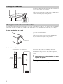
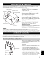
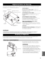
To enjoy quality sounds thoroughly, you need to place the speakers in their appropriate positions and install them correctly. After
deciding the speaker layout (see “Roles and Layout of Speakers” above), follow the procedure below to install the speakers.
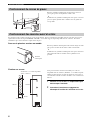
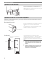
When placing the center speaker on top of the TV, use the
supplied fasteners to secure the speaker.
• Do not place the speaker on the TV if the top of the TV is not
level or if it is narrower than the bottom surface of the speaker.
Doing so may cause the speaker to fall. In this case, place the
speaker inside a TV rack or on a level floor.
• Before attaching the fasteners to the TV, clean the surface with a
dry cloth. A dirty or wet surface may weaken the adhesive force
and cause the speaker to fall.
• Do not touch the bonding surfaces of the fasteners after peeling
off the seals. Doing so may weaken the adhesive force and
cause the speaker to fall.
Roles and Layout of Speakers
Front Speaker (R)
Surround
speaker (L)
Subwoofer
Center speaker
Surround speaker (R)
Front speaker (L)
1.8 m
Surround back
(for NS-P336)
Notes
Placing the Speakers
Placing the center speaker
Peel off
the seal
Notes
Fastener

4
Placing the Speakers
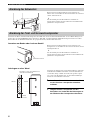
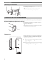
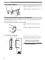
Attach the non-skid pads to the bottom of the subwoofer, and then
place the subwoofer on a level hard floor.
y
Using non-skid pads prevents the subwoofer from sliding when it
vibrates, and ensures quality sound production.
You can place the front and surround speakers on the floor or a rack, or attach them to a wall. Also, you can mount them on YAMAHA
speaker stands “SPS-200” or commercially available speaker stands. Please select an installation method that suits your room layout.
To place on the floor or a rack
Attach the non-skid pads to the bottom of each speaker, and then
place them on level hard surfaces.
y
Using non-skid pads prevents the speakers from sliding when
they vibrate, and ensures quality sound production.
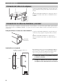
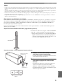
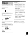
To attach to a wall
You can attach the speakers to a wall using commercially
available screws (Diameter: 3.5 to 4 mm (1/8” to 5/32”),
Length: 20 mm (25/32”) or more). One speaker requires two
screws. To attach all speakers to a wall, you need to prepare eight
screws.
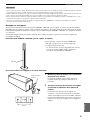
1 Install two screws in the wall where you want
to place the speaker.
2 Hang the speaker on the screws using the
holes in the back of the speaker.
Placing the subwoofer
Detach
Placing the front and surround speakers
110 mm
(4-1/16”)
10 mm (13/32”)
20 mm (25/32”)
or more
Screws (Diameter: 3.5 to 4 mm (1/8” to
5/32”), commercially available)
110 mm
(4-1/16”)
Non-skid pad

5
Placing the Speakers
English
• One speaker weighs about 1.0 kg (2 lbs 3 oz). To attach a speaker to a wall using screws, the wall must be firm. Do not attach a speaker
to a wall that is made of weak materials such as plaster or veneered woods. Doing so may cause the speaker to fall.
• Make sure you use specified screws to attach a speaker to a wall. Using clamps other than specified screws, such as short screws, nails,
or two-sided tape, may cause the speaker to fall.
• When connecting the speakers, fix the speaker cables in place so that cables do not loosen. If your foot or hand accidentally gets
caught on a loose speaker cable, the speaker may fall.
• After attaching each speaker, check that the speaker is fixed securely. YAMAHA will bear no responsibility for any accidents caused
by improper installations.
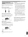
To mount on a speaker stand
You can mount the speakers on YAMAHA speaker stands “SPS-200” (set of two, optional) or commercially available
speaker brackets. When using commercially available speaker brackets, follow the procedure below to attach the supplied
mounting bracket to the speaker. When using YAMAHA speaker stands “SPS-200”, you do not need the following
procedure.
For information on how to mount a speaker on the speaker bracket, refer to the manual for the speaker brackets you want
to use.
YAMAHA speaker stand “SPS-200” (set of two, optional)
To mount a speaker on the YAMAHA speaker stand
“SPS-200”, refer to manual for the speaker stand.
* This product may not be available in certain regions.
For information, contact the store where you purchased
the product or your nearest YAMAHA dealer.
To attach to a bracket
1 Attach the mounting bracket to the speaker
using the supplied screw.
The jutting part of the bracket should fit to the groove
at the speaker base.
2 Mount the speaker on the speaker bracket
using the holes on the mounting bracket.
To mount a speaker on a commercially available
speaker bracket, you need two screws (Diameter:
4 mm (5/32”), spring washers, and washers. For more
information, refer to the manual for the speaker
bracket you want to use.
Notes
SPS-200
Mounting bracket
(supplied)
60 mm (2-3/8”)
Screw (supplied)

6
Placing the Speakers
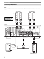
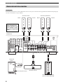
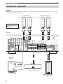
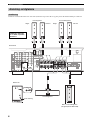
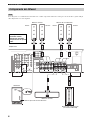
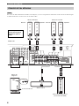
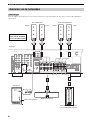
Do not connect the power cord of the subwoofer and other audio/video components into an AC outlet until all cable connections are
completed.
Connecting the speakers
Note
VOLUME INPUT
POWER
ON
OFF
INPUT
To AC outlet
Center speaker
Surround back speaker
(in NS-P336 systems)
Subwoofer
Amplifier
Front speakers Surround speakers
Right RightLeft Left
Note: The rear panel of
various amplifiers may
differ in appearance.

7
Placing the Speakers
English
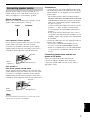
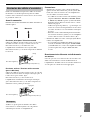
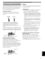
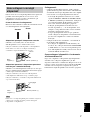
Keep the speaker cables as short as possible. Do not
bundle or roll up excess cable. If the connections are
faulty, you will hear no sound from the speakers.
Before connecting
Remove the insulation coating at the extremity of each
speaker cable by twisting the coating off.
Front speakers / Center speaker
Use the provided speaker cables (4 m). One side of the
speaker cable is red and the other side is black.
Connect the (+) terminals on both the speaker and the
amplifier using the red side of the cable. Connect the (–)
terminals on both components using the black side.
.
Rear speakers /
Rear center speaker (for NS-P336)
Use the provided speaker cables (15 m). One side of the
speaker cable has a gray line and the other side has no line.
Connect the (+) terminals on both the speaker and the
amplifier using the side with a gray line. Connect the (–)
terminals on both components using the side with no line.
Do not let uninsulated speaker wires touch each other as this
could damage the speaker or the amplifier.
Connections:
• Connect the front, center and surround speakers (and
surround back speaker for the NS-P336) to the speaker
output terminals on your amplifier using the included
speaker cables.
– The included speaker cables have labels marked
FRONT L, FRONT R, CENTER, REAR L, REAR R
(and REAR C for NS-P336). Connect each speaker
cable to the corresponding speaker as illustrated in
the figure on page 6.
– Connect each speaker making sure not to reverse the
polarity (+, –). If the speaker is connected with
reversed polarity, the sound will be unnatural and
lack bass.
– For the front and surround speakers only, connect
one speaker to the left (marked L) terminals on your
amplifier, and the other speaker to the right (marked
R) terminals.
• Connect the subwoofer to the line output (pin jack) ter-
minal(s) on the amplifier.
– To connect to a Yamaha DSP amplifier (or AV
receiver), connect the SUBWOOFER (or LOW
PASS, etc.) terminal on the rear of the DSP amplifier
(or AV receiver) to the INPUT terminal on the sub-
woofer.
Connecting components and the sub-
woofer to AC power
After you complete all speaker and subwoofer
connections, plug the amplifier, other audio/video
components, and the subwoofer into an AC outlet of
appropriate voltage.
Connecting speaker cables
Note
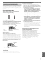
Good
No Good
Red: positive (+)
Black:
negative (–)
Red line
Red: positive (+)
Black:
negative (–)
Gray line

8
Placing the Speakers
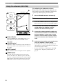
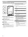
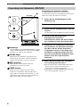
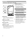
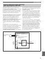
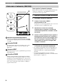
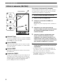
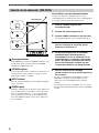
1 Power indicator
Lights up GREEN when the POWER switch (4) is
turned ON; turns off when the POWER switch is
turned OFF.
2 VOLUME control
Adjusts the volume level. Turn the control clockwise to
increase the volume, and counterclockwise to decrease
the volume.
3 INPUT terminal
Input terminal for line level signals from the amplifier.
4 POWER switch
Press this switch to the ON position to turn on the
power to the subwoofer. When the power of the sub-
woofer is on, the power indicator (1) on the rear panel
lights up green. Press this switch again to set it to the
OFF position to turn off the power of the subwoofer.
Pre-adjusting the subwoofer volume
Before you use the subwoofer, first adjust the vol-
ume balance between the subwoofer and the front
speakers by following the procedure below.
1 Set the VOLUME control to minimum (0).
2 Turn on the power to all other components.
3 Press the POWER switch to the ON position.
The power indicator on the rear panel lights up green.
4 Play a source that contains low-frequency
sounds. Adjust the amplifier’s volume
control to the desired listening level.
5 Increase the volume gradually to adjust the
volume balance between the subwoofer and
the front speakers. In most cases, set the
control to a level at which you hear slightly
more bass than when the subwoofer is not
used.
6 Adjust the volume of the entire sound system
using the amplifier’s volume control.
• If you replace the front speakers (NX-P200) with
other speakers, you must again balance the subwoofer
and surround speaker volume.
• For more information on adjusting the VOLUME
control, refer to “Frequency characteristics” on
page 11.
Using the subwoofer (SW-P330)
OFF
POWER
ON
VOLUME
INPUT
OFF
POWER
ON
VOLUME
INPUT
Rear panel

9
Placing the Speakers
English
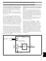
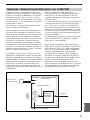
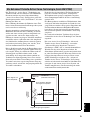
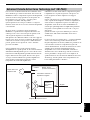
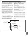
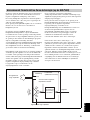
The theory behind Yamaha Active Servo Technol-
ogy is based on two factors: the Helmholtz resonator
and negative-impedance drive. Active Servo Pro-
cessing speakers reproduce the bass frequencies
through an “air woofer,” which is a port or opening
in the speaker’s cabinet.
This opening is used instead of, and performs the
functions of, a woofer in a conventionally designed
speaker system.
Thus, signals of low amplitude within the cabinet
can, according to Helmholtz resonance theory, be
output from this opening as waves of great ampli-
tude if the size of the opening and the volume of the
cabinet are in proportion to satisfy a certain ratio. In
order to accomplish this, moreover, the amplitudes
within the cabinet must be both precise and of suffi-
cient power because these amplitudes must over-
come the “load” presented by the air in the cabinet.
This problem is resolved by a design in which the
amplifier supplies special signals. If the electrical
resistance of the voice coil could be reduced to zero,
the movement of the speaker unit would become lin-
ear with respect to signal voltage. To accomplish
this, the system utilizes a special negative-imped-
ance output-drive amplifier that subtracts the output
impedance of the amplifier.
By employing negative-impedance drive circuits, the
amplifier is able to generate precise, low-amplitude,
low frequency waves with superior damping charac-
teristics.
These waves are then radiated from the cabinet
opening as high-amplitude signals. The system can,
therefore, by employing the negative-impedance
output drive amplifier and a speaker cabinet featur-
ing a Helmholtz resonator, reproduce an extremely
wide range of frequencies with outstanding sound
quality and low distortion.
The features described above combine to create the
fundamental structure of conventional Yamaha
Active Servo Technology.
Our new Active Servo Technology — Advanced
Yamaha Active Servo Technology — adopts
Advanced Negative Impedance Converter (ANIC)
circuits, which allow the conventional negative
impedance converter to dynamically vary to select
an optimum value for speaker impedance variation.
With these new ANIC circuits, Advanced Yamaha
Active Servo Technology provides a more stable
performance and improved sound pressure com-
pared to conventional Yamaha Active Servo Tech-
nology, resulting in more natural and dynamic bass
reproduction.
Advanced Yamaha Active Servo Technology (on the SW-P330)
High-amplitude
bass sound
Cabinet
Port
Air woofer
(Helmholtz resonator)
Advanced Negative
impedance Converter
Active Servo
Processing
Amplifier
Signals of low amplitude
Signals

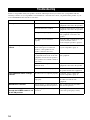
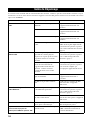
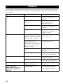
TROUBLESHOOTING
10
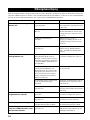
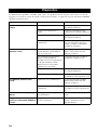
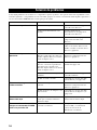
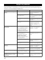
If there is any problem with your speakers, check the following items. If you cannot solve your problem with the
following remedies or if your problem is not listed below, contact the store where you purchased the product or your
nearest YAMAHA dealer and ask for assistance.
Troubleshooting
Problem Cause What to do
The speakers make no sound. The volume is set to minimum level. Adjust the volume on the A/V
equipment connected to the speakers.
The mute function is enabled. Disable the mute function on the A/V
equipment connected to the speakers.
The input setting is improper. Select the proper input setting on the
A/V equipment connected to the
speakers.
The cables are not connected
properly.
Check the cable connections in your
system. For details, refer to
“Connecting the speakers” (page 6).
A particular speaker makes no
sound.
Since each speaker has different roles
based on the types of sound each
produces, some speakers do not
produce sound in some cases.
For details, refer to “Roles and
Layout of Speakers” (page 3).
Depending on the speaker settings or
the playback modes used on the A/V
equipment connected to the speakers,
some speakers do not make sounds in
some cases.
For details, refer to the manual for the
A/V equipment.
The volume for the speaker is set to
minimum level.
Adjust the volume on the A/V
equipment connected to the speaker.
The cable is connected improperly. Check the cable connection between
the speaker and the A/V equipment.
The subwoofer makes strange
sounds.
The subwoofer is not placed properly. For details, refer to “Roles and
Layout of Speakers” (page 3).
The subwoofer cable is connected
improperly.
Check the cable connection between
the subwoofer and the A/V
equipment.
Sound level is too low. You are playing a sound source that
includes inadequate bass frequencies.
Play a sound source that includes
more bass frequencies.
Power is not supplied even
though the POWER switch is set
to the ON position.
The power plug is not securely
connected.
Turn the power switch OFF, then
connect the power plug securely.

11
English
Satellite speakers (Front/Surround)
Model name NX-S200
• Type .................. 2 way acoustic suspension magnetic shielding type
•Driver
...Tweeter: 2.5 cm (1 inch) balanced dome, magnetic shielding type
Woofer: 5 cm (2 inch) cone, magnetic shielding type × 2
• Nominal Input Power.................................................................30 W
• Maximum Input Power ............................................................100 W
• Impedance.....................................................................................6 Ω
• Frequency Response ............................................... 100 Hz – 40 kHz
• Sensitivity ..................................................................85 dB/2.83 Vm
• Dimensions (W × H × D) .....................................72 × 230 × 81 mm
(Approx. 2 13/16” × 9 1/16” × 3 3/16”)
• Weight.......................................................................................1.0 kg
(Approx. 2 lbs 3 oz)
Center speaker
Model name NX-C200
• Type .................. 2 way acoustic suspension magnetic shielding type
•Driver
...Tweeter: 2.5 cm (1 inch) balanced dome, magnetic shielding type
Woofer: 5 cm (2 inch) cone, magnetic shielding type × 2
• Nominal Input Power.................................................................30 W
• Maximum Input Power ............................................................100 W
• Impedance.....................................................................................6 Ω
• Frequency Response ............................................... 100 Hz – 40 kHz
• Sensitivity ..................................................................85 dB/2.83 Vm
• Dimensions (W × H × D) .....................................300 × 72 × 81 mm
(Approx. 11 13/16” × 2 13/16” × 3 3/16”)
• Weight.......................................................................................1.1 kg
(Approx. 2 lbs 6 oz)
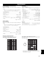
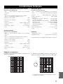
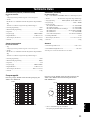
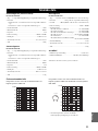
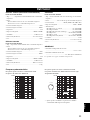
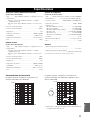
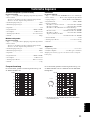
Frequency characteristics
The following graph* displays the frequency
characteristics of the SW-P330 subwoofer.
Subwoofer
Model name SW-P330
• Type........... Advanced YAMAHA Active Servo Technology System
• Driver ............................... 20 cm (8”) cone, magnetic shielding type
• Output Power ................................ 100 W (10% THD, 100 Hz, 5 Ω)
• Frequency Response..................................................30 Hz – 200 Hz
• Power Supply
U.S.A. and Canada models ..................................AC 120 V, 60 Hz
Australia model ....................................................AC 240 V, 50 Hz
U.K. and Europe models......................................AC 230 V, 50 Hz
Asia model .............................................. AC 220-240 V, 50/60 Hz
Korea model.........................................................AC 220 V, 60 Hz
General (Taiwan) model.......................... AC 110-120 V, 50/60 Hz
• Power Consumption.................................................................. 85 W
• Dimensions (W × H × D)................................. 232 × 415 × 388 mm
(Approx. 9 1/8” × 16 11/32” × 15 9/32”)
• Weight ...................................................................................... 9.6 kg
(Approx. 21 lbs 3 oz)
General
• Operating Temperature range.............+5°C to +35°C (41°F to 95°F)
• Operating Humidity Range .................. 5 to 90% (No Condensation)
The above specifications are subject to change without notice.
The following graph* displays the frequency
characteristics of the SW-P330 subwoofer combined with
NX-S200 speakers.
* This diagram does not depict actual frequency response
characteristics accurately.
Specifications
20 50 100 200 500 Hz
40
50
60
70
80
90
100 dB
20 50 100 200 500 Hz
40
50
60
70
80
90
100 dB
SW-P330
NX-S200
VOLUME

PRÉCAUTIONS
1
Pour profiter au mieux de votre acquisition, lisez attentivement ce
mode d’emploi. Conservez-le soigneusement pour référence.
2
Installez les enceintes dans un endroit frais, sec, loin des fenêtres et
des sources de chaleur et de vibration, des poussières, de l’humidité
et du froid. Évitez les sources de ronflements électriques que sont
les transformateurs et les moteurs. Pour éviter les risques d’incendie
et de secousses électriques, n’exposez pas les enceintes à la pluie ni
à l’humidité.
3 Pour éviter que la menuiserie des enceintes ne se déforme ou ne
se décolore, n’exposez pas les enceintes à la lumière directe du
soleil ni à une humidité excessive.
4 Évitez d’installer les enceintes dans un endroit exposé à la chute
d’objets ou encore à l’écoulement ou aux éclaboussures de
liquides.
5 Ne posez pas les objets suivants sur le dessus des enceintes:
– D’autres appareils qui pourraient endommager ou décolorer
la menuiserie des enceintes;
– Des objets enflammés (par exemple, des bougies) qui
pourraient endommager les enceintes, provoquer une
blessure, voire un incendie;
– Des récipients contenant des liquides qui pourraient se
renverser, endommager les enceintes ou être à l’origine d’une
secousse électrique.
6
Ne placez pas les enceintes dans un endroit où elles peuvent être
heurtées, directement ou par la chute d’objets. Un emplacement
stable garantit l’obtention de meilleures sonorités.
7 Placer les enceintes sur des étagères ou dans un meuble qui
contient également la platine de lecture, peut entraîner un
phénomène de bouclage.
8 La détermination d’un endroit convenable est de votre
responsabilité. YAMAHA ne saurait être responsable des accidents
provoqués par le choix d’un emplacement qui ne conviendrait pas,
ni par l’installation incorrecte des enceintes.
9
En cas de distorsion, réduisez le niveau de sortie de l’amplificateur.
N’excitez pas l’amplificateur au point qu’il écrête. Dans ce cas en
effet, les enceintes pourraient être endommagées.
10 Vous devez être très attentif, si l’amplificateur peut délivrer une
puissance supérieure à la puissance maximale admissible par les
enceintes, à ce que cela ne se produise pas.
11 Ne nettoyez pas la menuiserie des enceintes avec un produit
chimique qui peut endommager leur finition. Utilisez un chiffon
sec et propre.
12 Ne tentez pas de modifier les enceintes ni de les réparer.
Consultez le service YAMAHA compétent si une réparation est
nécessaire. Pour quelque raison que ce soit, ne démontez pas la
menuiserie des enceintes.
13 Prenez connaissance des erreurs fréquentes, mentionnées dans la
section “Guide de Dépannage”, avant de conclure que les
enceintes sont défectueuses.
En ce qui concerne le SW-330
1 Ne le faites pas fonctionner à l’envers. Il peut surchauffer et être
endommagé.
2
Manœuvrez les commutateurs et les commandes avec précaution,
veillez aux câbles de liaison. Avant de déplacer cet appareil,
débranchez la fiche du cordon d’alimentation et les câbles qui le
relient aux autres appareils. Ne tirez pas sur les câbles.
3
Cet appareil étant doté d’un amplificateur de puissance, il rayonne
de la chaleur, à travers son panneau arrière. Placez cet appareil
loin des murs et ménagez au moins 20 cm au-dessus, derrière et
sur chaque côté pour réduire les risques d’incendie ou
d’endommagement. Par ailleurs, ne positionnez pas cet appareil
de telle manière que son panneau arrière soit tourné vers le
plancher ou en contact avec une paroi.
4 Si vous utilisez un humidificateur, veillez à réduire les risques de
condensation à l’intérieur de cet appareil en ménageant
suffisamment d’espace libre autour de lui et en réglant
l’humidificateur à une valeur convenable. La condensation peut
provoquer un incendie, endommager l’appareil ou être la cause
d’une secousse électrique.
5 Ne couvrez pas le panneau arrière d’un journal, d’une nappe,
d’un rideau, etc., ce qui pourrait empêcher la chaleur de
s’évacuer. Une augmentation anormale de la température
intérieure de l’appareil peut provoquer un incendie, endommager
l’appareil ou entraîner des blessures.
6 Ne branchez pas la fiche du cordon d’alimentation sur une prise
secteur aussi longtemps que tous les raccordements ne sont pas
terminés.
7 La tension à utiliser est indiquée sur le panneau arrière.
Alimenter cet appareil sous une tension supérieure à la tension
prescrite, peut provoquer un incendie, endommager l’appareil ou
entraîner des blessures. YAMAHA ne saurait être responsable
des dommages résultant de l’utilisation d’une tension
d’alimentation différente de la tension prescrite.
8 Pour éviter les dommages de la foudre, débranchez la fiche du
cordon d’alimentation pendant les orages.
9 Les fréquences très graves produites par cet appareil peuvent agir
sur la platine de lecture et provoquer un bouclage. En ce cas,
éloignez l’appareil de la platine de lecture.
10 Cet appareil peut être endommagé par la production permanente
de certaines fréquences. Par exemple, si un signal sinusoïdal
entre 20 et 50 Hz est produit par un disque d’essai ou des sons
très graves sont générés par un instrument de musique
électronique, etc., ou encore si le saphir de la platine de lecture
frotte sur le microsillon, il sera bon de réduire le niveau de sortie
pour éviter les dommages.
11
Si vous notez que cet appareil produit de la distorsion (par
exemple, des bruits secs et répétés, un martèlement), réduisez le
niveau de sortie. Les fréquences très graves que contiennent
certaines pistes sonores de film ou certains passages de musique
populaire, peuvent endommager cet appareil.
12 Les vibrations produites par les fréquences très graves peuvent
déformées les images affichées sur le téléviseur. En ce cas,
éloignez l’appareil du téléviseur.
13 Pour débrancher la fiche du cordon d’alimentation, saisissez la
fiche mais ne tirez pas sur le cordon.
14
Si vous envisagez de ne pas utiliser cet appareil pendant une
longue période (par exemple, pendant des congés), débranchez la
fiche du cordon d’alimentation au niveau de la prise secteur.
15 N’exercez aucune pression excessive sur le tissu du caisson de
graves. Le tissus pourrait se rompre, ou le caisson pourrait se
renverser et provoquer un accident.
16
Ne posez aucun objet fragile au voisinage du caisson de graves.
Les ondes de pression produites par le caisson peuvent briser ou
endommager un objet fragile, et entraîner un accident.
POUR LES CONSOMMATEURS CANADIENS
Pour éviter les chocs électriques, introduire la lame la plus
large de la fiche dans la borne correspondante de la prise et
pousser jusqu’au fond.
Cet appareil numérique de la classe B est conforme à la norme
NMB-003 du Canada.
AVERTISSEMENT
POUR RÉDUIRE LES RISQUES D’INCENDIE OU DE
SECOUSSE ÉLECTRIQUE, N’EXPOSEZ PAS CET APPA-
REIL À LA PLUIE OU À L’HUMIDITÉ.
ATTENTION: VEUILLEZ LIRE CE QUI SUIT AVANT D’UTILISER L’APPAREIL.

1
Français
Cet ensemble d’enceintes acoustiques comprend les éléments
mentionnés dans le tableau ci-dessous.
Assurez-vous que tous les éléments du tableau vous ont été livrés.
Caisson de graves Active Servo avec amplificateur intégré.
Ce caisson de graves (SW-P330) bénéficie de la technologie
YAMAHA Advanced Active Servo mise au point pour
reproduire plus fidèlement les sons très graves. Ces sons très
graves ajoutent du réalisme aux sonorités émises par votre
chaîne stéréophonique et leur apportent une note “salle de
cinéma”.
Introduction................................................... 2
Quelques mots sur ce mode d’emploi........................... 2
Contenu de l’emballage ............................... 2
Rôle et Disposition des Enceintes.............. 3
Disposition des Enceintes........................... 3
Positionnement de l’enceinte centrale .......................... 3
Positionnement du caisson de graves............................ 4
Positionnement des enceintes avant et arrière .............. 4
Raccordement des enceintes ......................................... 6
Connexion des câbles d’enceintes ................................ 7
Utilisation du Subwoofer(SW-P330)............................ 8
Technologie “Advanced Yamaha Active Servo”
(sur le
SW-P330).................................................. 9
Guide de Dépannage.................................. 10
Caractéristiques Techniques..................... 11
Nom de modèle Usage
Nbre de
pièces
NS-P330
NX-S200
Enceintes satellite
(pour l’avant, pour
l’arrière)
4
NX-C200 Enceinte centrale 1
SW-P330 Caisson de graves 1
NS-P336
NX-S200
Enceintes satellite
(pour l’avant, pour
l’arrière)
5
NX-C200 Enceinte centrale 1
SW-P330 Caisson de graves 1
Table des Matières

INTRODUCTION
2
Le “NS-P330/NS-P336” comporte 4/5 enceintes satellites (avant et arrière), une enceinte centrale et un caisson de graves.
N’hésitez pas à profiter des belles sonorités produites par cet ensemble à 5.1/6.1 voies YAMAHA “NS-P330/NS-P336”.
• Ce mode d’emploi n’aborde que l’installation et les caractéristiques des enceintes. Pour de plus amples détails concernant
les enceintes et les autres appareils audiovisuels, reportez-vous au mode d’emploi qui les accompagne.
• Ce mode d’emploi a été imprimé avant que la tête de série ne soit mise en fabrication. Pour des raisons techniques ou
autres, les caractéristiques définitives des appareils ou leur présentation peuvent différer de ce qu’il est dit dans ce mode
d’emploi.
Cet ensemble comprend les éléments suivants. Avant de procéder à l’installation des enceintes, assurez-vous que vous les
éléments faisant partie de l’emballage.
Câbles et pièces d’installation
Introduction
Enceintes satellite (pour l’avant,
pour l’arrière)
surround arrière
*
)
NX-S200
Enceinte centrale
NX-C200 (1 pièce)
Caisson de graves
SW-P330 (1 pièce)
*
pour NS-P336
4 pièces :NS-P330
5 pièces :NS-P336
Quelques mots sur ce mode d’emploi
Contenu de l’emballage
Câble pour le caisson de graves
(1 fiche, 5 m, 1 pièce)
Vis (M4 × 10)
(pour les enceintes avant et arrière)
Câble de commande d’ensemble
(4 m/3 pièces)
Garnitures antidérapantes
(pour le caisson de graves,
1 jeu: 4 pièces)
Garniture
(pour l’enceinte centrale, 2 pièces)
Garnitures antidérapantes
(pour les enceintes avant et
arrière)
Platines de fixation
(pour les enceintes avant et arrière)
(15 m)
2 pièces : NS-P330
3 pièces : NS-P336
4 pièces : NS-P330
5 pièces : NS-P336
4 jeux (16pièces) : NS-P330
5 jeux (20 pièces) : NS-P336
4 pièces : NS-P330
5 pièces : NS-P336

3
Français
Chaque enceinte joue un rôle bien précis lié aux sons produits. Cette section traite du rôle de chaque enceinte et de l’emplacement conseillé.
Enceinte centrale
Placez-la sur le dessus du téléviseur ou dans le meuble télévision
de telle manière que la face avant de l’enceinte et celle du
téléviseur soit dans le même plan vertical.
Rôle principal de cette enceinte: Cette enceinte produit les sons
qui viennent du centre de l’image, tels que les dialogues et les
chants.
Enceintes avant (G, D)
Placez-les de chaque côté du téléviseur et à égale distance.
Rôle principal de cette enceinte: Ces enceintes produisent les
sons des voies avant (stéréophonie) et les effets sonores.
Enceintes arrière (G, D)
Placez-les derrière la position d’écoute et de chaque côté. (Nous
vous conseillons de les disposer à 1,8 m de hauteur et de les
diriger vers la position d’écoute.)
Rôle principal de cette enceinte: Ces enceintes produisent les
sons d’ambiance et les effets sonores.
Enceinte Surround arrière (système NS-P336
uniquement)
Placez l’enceinte Surround arrière derrière la position d’écoute, à
mi-chemin exactement entre les enceintes Surround arrière et à
environ 1,8 m du sol.
Caisson de graves
Placez-le près d’une enceinte avant et dirigez-le légèrement vers le
centre de la pièce de manière à réduire les réflexions sur les murs.
Rôle principal de cette enceinte: Cette enceinte produit les sons
graves et très graves (LFE) que contiennent les signaux Dolby
Digital et DTS.
• Si les enceintes perturbent la réception de la télévision, du bruit peut apparaître sur l’écran. Dans ce cas, éloignez un peu les enceintes du téléviseur.
•
Les sons graves produits par le caisson de graves peuvent être perçus différemment selon la position d’écoute et l’emplacement du caisson de graves.
Pour profiter des sons attendus, modifiez légèrement la disposition du caisson de graves en fonction de la position d’écoute.
Pour que les sons produits soient de qualité, vous devez disposer convenablement les enceintes et les installer de la manière voulue. Après avoir choisi
une disposition des enceintes (reportez-vous à “Rôle et Disposition des Enceintes” ci-dessus), procédez comme il est dit ci-dessus pour les installer.
Pour fixer l’enceinte centrale sur le dessus du téléviseur, utilisez
les garnitures fournies.
• Ne placez pas l’enceinte sur le dessus du téléviseur si ce dessus
n’est pas horizontal ou s’il est plus étroit que la base de
l’enceinte. En effet, l’enceinte pourrait tomber. Dans cette
situation, placez l’enceinte à l’intérieur du meuble télévision ou
sur le plancher.
• Avant de poser les garnitures sur le téléviseur, nettoyez sa
surface avec un chiffon sec. Si la surface est sale ou humide, la
force d’adhésion est réduite et l’enceinte pourrait
ultérieurement tomber.
• Après avoir retiré la feuille de protection, ne touchez pas les
surfaces adhésives des garnitures. Cela réduirait la force
d’adhésion de ces garnitures et l’enceinte pourrait
ultérieurement tomber.
Rôle et Disposition des Enceintes
Enceinte avant (D)
Enceinte
arrière (G)
Caisson de graves
Enceinte centrale
Enceinte arrière (D)
Enceinte avant (G)
1,8 m
Surround arrière
(pour
NS-P336)
Remarques
Disposition des Enceintes
Positionnement de l’enceinte centrale
Retirez la
feuille de
protection
Remarques
Garniture

4
Disposition des Enceintes
Fixez les garnitures antidérapantes sur le fond du caisson de
graves puis posez-le sur un plancher solide et dur.
y
L’utilisation des garnitures antidérapantes évite que le caisson de
graves ne glisse quand il vibre et améliore donc la qualité des
sons produits.
Les enceintes avant et arrière peuvent être posées sur le plancher, placées à l’intérieur d’un meuble ou fixées aux murs. Vous pouvez
également les monter sur un pied YAMAHA “SPS-200”, ou tout autre support adéquat disponible dans le commerce. Choisissez
l’installation qui convient le mieux compte tenu de la pièce.
Pose sur le plancher ou dans un meuble
Fixez les garnitures antidérapantes sur le fond de chaque enceinte
puis posez l’enceinte sur une surface solide et horizontale.
y
L’utilisation des garnitures antidérapantes évite que l’enceinte ne
glisse quand elle vibre et améliore donc la qualité des sons
produits.
Fixation sur un mur
Vous pouvez fixer les enceintes sur un mur grâce à des vis
disponibles dans le commerce (Diamètre: 3,5 à 4 mm, Longueur:
20 mm ou plus). Chaque enceinte doit être fixée au moyen de 2
vis. Pour fixer toutes les enceintes aux murs, vous avez besoin de
huit vis.
1 Posez 2 vis sur le mur, à l’emplacement que
doit occuper l’enceinte.
2 Accrochez l’enceinte en engageant les
découpes à l’arrière de l’enceinte sur les vis.
Positionnement du caisson de graves
Détachez
Positionnement des enceintes avant et arrière
110 mm
10 mm
20 mm ou plus
Vis (diamètre 3,5 à 4 mm, disponibles
dans le commerce)
110 mm
Garniture
antidérapante

5
Français
Disposition des Enceintes
• Une enceinte pèse environ 1,0 kg. Pour fixer une enceinte au mur au moyen de vis, il faut que le mur soit solide. Ne tentez pas de fixer
une enceinte sur un mur peu solide, en plâtre ou en bois plaqué. En effet, l’enceinte pourrait tomber.
• Veillez à utiliser les vis prescrites lorsque vous fixez une enceinte sur un mur. L’utilisation de fixations autres que les vis prescrites (vis
plus courtes, clous, ruban adhésif double-face) est déconseillée car l’enceinte pourrait se détacher et tomber.
• Fixez soigneusement les câbles d’enceinte de manière qu’ils ne soient pas libres. Un câble libre peut être accidentellement accroché
d’une main ou d’un pied, ce qui peut provoquer la chute de l’enceinte.
• Après pose de l’enceinte, assurez-vous qu’elle est soigneusement fixée. YAMAHA ne saurait être responsable des accidents
provoqués par une installation défectueuse.
Montage sur un support
Vous pouvez monter les enceintes sur les pieds YAMAHA “SPS-200” (jeu de 2 pieds, en option) ou tout autre support
disponible dans le commerce. Dans le cas d’un support du commerce, procédez comme il est dit ci-dessous pour assurer
le maintien de la platine de fixation à l’enceinte. Si vous utilisez un pied YAMAHA “SPS-200”, il est inutile d’effectuer
ces opérations.
Pour de plus amples détails concernant le montage de l’enceinte au support, reportez-vous au mode d’emploi qui
accompagne le support.
Pied d’enceinte YAMAHA “SPS-200” (jeu de 2 pieds, en option)
Pour monter une enceinte sur un pied YAMAHA
“SPS-200”, reportez-vous au mode d’emploi qui
accompagne le pied d’enceinte.
* Le pied d’enceinte n’est pas disponible dans tous les
pays. Pour de plus amples détails, consultez le
revendeur ou le distributeur YAMAHA.
En cas de fixation à un support ou un socle d’enceinte
1 Montez la platine de fixation sur l’enceinte au
moyen de la vis fournie.
La partie de la platine faisant saillie doit être en
regard de la découpe pratiquée dans la base de
l’enceinte.
2 Assurez le maintien de l’enceinte au support
en utilisant les découpes de la platine de
fixation.
Pour monter une enceinte sur un support du
commerce, vous avez besoin de deux vis (Diamètre:
4 mm), de rondelles ressort et de rondelles ordinaires.
Pour de plus amples détails concernant cette question,
reportez-vous au mode d’emploi qui accompagne le
support.
Remarques
Platine de fixation
(fournie)
Vis (fournie)
60 mm
SPS-200

6
Disposition des Enceintes
Ne branchez pas la fiche du cordon d’alimentation du caisson de graves ni celle des autres appareils audiovisuels aussi longtemps que
tous les raccordements ne sont pas terminés.
Raccordement des enceintes
Remarques
VOLUME INPUT
POWER
ON
OFF
INPUT
Vers une prise secteur
Enceinte centrale
Enceinte Surround arrière
(pour le système NS-P336)
Caisson de
graves
Amplificateur
Enceintes avant Enceintes d’ambiance
Droite DroiteGauche Gauche
Remarque: Le panneau
arrière d’amplificateur
illustré ci-dessous n’est
qu’un exemple; l’aspect
varie selon l’amplificateur
utilisé.
Seite wird geladen ...
Seite wird geladen ...
Seite wird geladen ...
Seite wird geladen ...
Seite wird geladen ...
Seite wird geladen ...
Seite wird geladen ...
Seite wird geladen ...
Seite wird geladen ...
Seite wird geladen ...
Seite wird geladen ...
Seite wird geladen ...
Seite wird geladen ...
Seite wird geladen ...
Seite wird geladen ...
Seite wird geladen ...
Seite wird geladen ...
Seite wird geladen ...
Seite wird geladen ...
Seite wird geladen ...
Seite wird geladen ...
Seite wird geladen ...
Seite wird geladen ...
Seite wird geladen ...
Seite wird geladen ...
Seite wird geladen ...
Seite wird geladen ...
Seite wird geladen ...
Seite wird geladen ...
Seite wird geladen ...
Seite wird geladen ...
Seite wird geladen ...
Seite wird geladen ...
Seite wird geladen ...
Seite wird geladen ...
Seite wird geladen ...
Seite wird geladen ...
Seite wird geladen ...
Seite wird geladen ...
Seite wird geladen ...
Seite wird geladen ...
Seite wird geladen ...
Seite wird geladen ...
Seite wird geladen ...
Seite wird geladen ...
Seite wird geladen ...
Seite wird geladen ...
Seite wird geladen ...
Seite wird geladen ...
Seite wird geladen ...
Seite wird geladen ...
Seite wird geladen ...
Seite wird geladen ...
Seite wird geladen ...
Seite wird geladen ...
Seite wird geladen ...
Seite wird geladen ...
Seite wird geladen ...
Seite wird geladen ...
Seite wird geladen ...
Seite wird geladen ...
Seite wird geladen ...
Seite wird geladen ...
Seite wird geladen ...
Seite wird geladen ...
Seite wird geladen ...
-
 1
1
-
 2
2
-
 3
3
-
 4
4
-
 5
5
-
 6
6
-
 7
7
-
 8
8
-
 9
9
-
 10
10
-
 11
11
-
 12
12
-
 13
13
-
 14
14
-
 15
15
-
 16
16
-
 17
17
-
 18
18
-
 19
19
-
 20
20
-
 21
21
-
 22
22
-
 23
23
-
 24
24
-
 25
25
-
 26
26
-
 27
27
-
 28
28
-
 29
29
-
 30
30
-
 31
31
-
 32
32
-
 33
33
-
 34
34
-
 35
35
-
 36
36
-
 37
37
-
 38
38
-
 39
39
-
 40
40
-
 41
41
-
 42
42
-
 43
43
-
 44
44
-
 45
45
-
 46
46
-
 47
47
-
 48
48
-
 49
49
-
 50
50
-
 51
51
-
 52
52
-
 53
53
-
 54
54
-
 55
55
-
 56
56
-
 57
57
-
 58
58
-
 59
59
-
 60
60
-
 61
61
-
 62
62
-
 63
63
-
 64
64
-
 65
65
-
 66
66
-
 67
67
-
 68
68
-
 69
69
-
 70
70
-
 71
71
-
 72
72
-
 73
73
-
 74
74
-
 75
75
-
 76
76
-
 77
77
-
 78
78
-
 79
79
-
 80
80
-
 81
81
-
 82
82
-
 83
83
-
 84
84
-
 85
85
-
 86
86


Yamaha P360 Bedienungsanleitung
- Typ
- Bedienungsanleitung
in anderen Sprachen
- English: Yamaha P360 Owner's manual
- français: Yamaha P360 Le manuel du propriétaire
- español: Yamaha P360 El manual del propietario
- italiano: Yamaha P360 Manuale del proprietario
- Nederlands: Yamaha P360 de handleiding
- dansk: Yamaha P360 Brugervejledning
- svenska: Yamaha P360 Bruksanvisning
- Türkçe: Yamaha P360 El kitabı
- română: Yamaha P360 Manualul proprietarului
Verwandte Artikel
-
Yamaha NS-C200 Bedienungsanleitung
-
Yamaha NS-P440 Bedienungsanleitung
-
Yamaha NS-P430 Bedienungsanleitung
-
-
-
-
-
Yamaha NS-SW210 Bedienungsanleitung
-
-
Andere Dokumente
-
TEAC LS-W300 Benutzerhandbuch
-
Pioneer S-C73A Benutzerhandbuch
-
JVC SP-F303C Benutzerhandbuch
-
Sony SSK10ED Benutzerhandbuch
-
Kenwood KS-708HT Benutzerhandbuch
-
-
-
MaxMusic MAX28 Bedienungsanleitung
-
Pioneer HTP-SLH600 Bedienungsanleitung
-