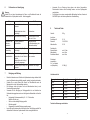
WALTHER PILOT PILOT WA 600 Bedienungsanleitung
- Kategorie
- Power-Feinsprühsysteme
- Typ
- Bedienungsanleitung

Betriebsanleitung / Operating Instructions
PILOT WA 600 / WA 610
WA 625 / WA 635
Automatische Spritzpistolen / Automatic Spray Guns

Seite 6 - 17
Page 18 - 29

54
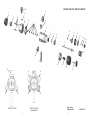
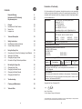
WA 600 / WA 610 / WA 625 / WA 635
Rep.-Set Nr.:
Repair Set No.: V 16 600 02 .. 3
1
2
28
26
3
25
10
9
8
7
11
12
13
14
23
15
4
6
16
17
18
22
21
20
19
29
5
24
27
2929
23
2929
23 23
WA 600 / WA 625 WA 610 / WA 635
Umlaufversion

76
Inhaltsverzeichnis
Explosionszeichnung 4
Konformitätserklärung 7
Ersatzteilliste 8
1 Allgemeines 10
1.1 Kennzeichnung des Modells 10
1.2 Bestimmungsmäßige Verwendung 10
1.3 Sachwidrige Verwendung 11
2 Technische Beschreibung 11
3 Sicherheitshinweise 12
3.1 Kennzeichnung der Sicherheitshinweise 12
3.2 Allgemeine Sicherheitshinweise 12
4 Inbetriebnahme 13
4.1 Steuerluft-, Zerstäuberluft- und Materialanschluss 13
4.2 Spritzbildprobe erzeugen 13
4.3 Spritzbild verändern 14
4.4 Mängel eines Spritzbildes beheben 14
5 Spritzautomat umrüsten 14
5.1 Luftkopf wechseln 15
5.2 Materialdüse wechseln 15
5.3 Materialnadel wechseln 15
5.4 Nadelpackung wechseln 15
6 Fehlersuche und -beseitigung 16
7 Reinigung und Wartung 16
8 Technische Daten 17
Konformitätserklärung
Wir, der Gerätehersteller, erklären in alleiniger Verantwortung, dass das Produkt in der
untenstehenden Beschreibung den einschlägigen grundlegenden Sicherheits- und
Gesundheitsanforderungen entspricht. Bei einer nicht mit uns abgestimmten Änderung
an dem Gerät oder bei einer unsachgemäßen Verwendung verliert diese Erklärung ihre
Gültigkeit.
Hersteller WALTHER Spritz- und Lackiersysteme GmbH
Kärntner Str. 18 - 30
D - 42327 Wuppertal
Tel.: +49(0)202 / 787 - 0
Fax: +49(0)202 / 787 - 2217
www.walther-pilot.de • e-mail: [email protected]
Typenbezeichnung Automatische Spritzpistole
PILOT WA 600 / WA 610 / WA 625 / WA 635
WA 600 V 20 600 WA 625 MP V 20 607
WA 610-U V 20 601 WA 635 MP-U V 20 608
Verwendungszweck Verarbeitung spritzbarer Materialien
Angewandte Normen und Richtlinien
EG-Maschinenrichtlinien 2006/42/EG
2014/34/EU (ATEX Richtlinien)
DIN EN ISO 12100
DIN EN 1953 DIN EN 13463-1
DIN EN 1127-1 DIN EN 13463-5
Spezifikation im Sinne der Richtlinie 2014/34/EU
Kategorie 2 Gerätebezeichnung II 2 G c T 5
Tech.File,Ref.:
2406
Bevollmächtigt mit der Zusammenstellung der technischen Unterlagen:
Nico Kowalski, WALTHER Spritz- und Lackiersysteme GmbH, Kärntner Str. 18 - 30
D- 42327 Wuppertal
Besondere Hinweise :
Das Produkt ist zum Einbau in ein anderes Gerät bestimmt. Die Inbetriebnahme ist
so lange untersagt, bis die Konformität des Endproduktes mit der Richtlinie
2006/42/EG festgestellt ist.
Wuppertal, den 02. November 2016
Name: Torsten Bröker
Stellung im Betrieb: Leiter der Konstruktion und Entwicklung
Diese Erklärung ist keine Zusicherung von Eigenschaften im Sinne der Produkthaftung. Die Sicherheitshinweise
der Produktdokumentation sind zu beachten.
ppa.

98
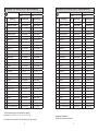
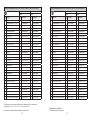
Ersatzteilliste PILOT WA 600 / WA 610 / WA 625 und WA 635
PILOT WA 600 PILOT WA 610-U
V 20 600 V 20 601
Pos. Bezeichnung Stck Ersatzteilnummer Stck Ersatzteilnummer
1
Luftkopf 0,3 - 1,5 mm Ø
1
V 10 151 30 039*
1
V 10 151 30 039*
Luftkopf 1,8 - 2,2 mm Ø V 10 151 30 189* V 10 151 30 189*
2 Materialdüse 1 V 10 151 40 .. 3* 1 V 10 151 40 .. 3*
3 Vorderteil 1 V 20 410 10 000 1 V 20 420 10 000
4 Nadelpackung kompl. 1 V 09 001 80 000 1 V 09 001 80 000
5 Befestigungsbolzen 1 V 20 310 09 003 1 V 20 310 09 003
6 Kolbengehäuse 1 V 20 410 40 000 1 V 20 410 40 000
7 Topfmanschette 1 V 09 220 27 000 1 V 09 220 27 000
8 O-Ring 1 V 09 103 22 001 1 V 09 103 22 001
9 Kolbenbuchse 1 V 20 410 24 004 1 V 20 410 24 004
10 O-Ring 1 V 09 102 67 000 1 V 09 102 67 000
11 Kolben 1 V 20 410 23 004 1 V 20 410 23 004
12 Topfmanschette 1 V 09 220 28 000 1 V 09 220 28 000
13 Klemmscheibe 1 V 20 410 18 004 1 V 20 410 18 004
14 O-Ring 1 V 09 102 20 001 1 V 09 102 20 001
15 Druckstück 1 V 20 410 39 004 1 V 20 410 39 004
16 Kolbenschraube 1 V 20 410 16 004 1 V 20 410 16 004
17 Materialnadel 1 V 20 410 30 .. 3* 1 V 20 410 30 .. 3*
18 Kolbenfeder 1 V 20 410 17 000 1 V 20 410 17 000
19 Gewindebuchse 1 V 20 410 27 000 1 V 20 410 27 000
20 Nadelfeder 1 V 20 410 28 003 1 V 20 410 28 003
21 Regelkappe 1 V 20 410 29 000 1 V 20 410 29 000
22 Zugstange kompl. 1 V 20 410 36 000 1 V 20 410 36 000
23 Spritzluftanschluss 1 V 20 410 19 005 1 V 20 410 19 005
24 Steuerluftanschluss 1 V 66 101 53 322 1 V 66 101 53 322
25 Dichtung 1 V 09 001 81 000 1 V 09 001 81 000
26 Dichtung 1 V 09 002 51 000 2 V 09 002 51 000
27 Materialanschluss 1 V 20 410 13 003 2 V 20 410 13 003
28 Innensechskantschraube 3 V 20 410 37 003 3 V 20 410 37 003
29 Rund- u. Breitstrahlregelung 2 V 20 410 20 000 2 V 20 410 20 000
• Bei Ersatzteilbestellung bitte entsprechende Größe angeben,
Durchmesser: 0,3 • 0,5 • 0,8 • 1,0 • 1,2 • 1,5 • 1,8 • 2,0 • 2,2 mm
Wir empfehlen, alle fett gedruckten Teile (Verschleissteile) am Lager zu halten.
Ersatzteilliste PILOT WA 600 / WA 610 / WA 625 und WA 635
PILOT WA 625-MP PILOT WA 635-MP-U
V 20 607 V 20 608
Pos. Bezeichnung Stck Ersatzteilnummer Stck Ersatzteilnummer
1
Luftkopf 0,3 - 1,5 mm Ø
1
V 10 141 30 038
1
V 10 141 30 038
Luftkopf 1,8 - 2,2 mm Ø V 10 141 30 188 V 10 141 30 188
2 Materialdüse 1 V 10 151 40 .. 3* 1 V 10 151 40 ..3*
3 Vorderteil 1 V 20 410 10 000 1 V 20 420 10 000
4 Nadelpackung kompl. 1 V 09 001 80 000 1 V 09 001 80 000
5 Befestigungsbolzen 1 V 20 310 09 003 1 V 20 310 09 003
6 Kolbengehäuse 1 V 20 410 40 000 1 V 20 410 40 000
7 Topfmanschette 1 V 09 220 27 000 1 V 09 220 27 000
8 O-Ring 1 V 09 103 22 001 1 V 09 103 22 001
9 Kolbenbuchse 1 V 20 410 24 004 1 V 20 410 24 004
10 O-Ring 1 V 09 102 67 000 1 V 09 102 67 000
11 Kolben 1 V 20 410 23 004 1 V 20 410 23 004
12 Topfmanschette 1 V 09 220 28 000 1 V 09 220 28 000
13 Klemmscheibe 1 V 20 410 18 004 1 V 20 410 18 004
14 O-Ring 1 V 09 102 20 001 1 V 09 102 20 001
15 Druckstück 1 V 20 410 39 004 1 V 20 410 39 004
16 Kolbenschraube 1 V 20 410 16 004 1 V 20 410 16 004
17 Materialnadel 1 V 20 410 30 .. 3* 1 V 20 410 30 ..3*
18 Kolbenfeder 1 V 20 410 17 000 1 V 20 410 17 000
19 Gewindebuchse 1 V 20 410 27 000 1 V 20 410 27 000
20 Nadelfeder 1 V 20 410 28 003 1 V 20 410 28 003
21 Regelkappe 1 V 20 410 29 000 1 V 20 410 29 000
22 Zugstange kompl. 1 V 20 410 36 000 1 V 20 410 36 000
23 Spritzluftanschluss 1 V 20 607 03 005 1 V 20 607 03 005
24 Steuerluftanschluss 1 V 66 101 53 322 1 V 66 101 53 322
25 Dichtung 1 V 09 001 81 000 1 V 09 001 81 000
26 Dichtung 1 V 09 002 51 000 2 V 09 002 51 000
27 Materialanschluss 1 V 20 410 13 003 2 V 20 410 13 003
28 Innensechskantschraube 3 V 20 410 37 003 3 V 20 410 37 003
29 Rund- u. Breitstrahlregelung 2 V 20 410 20 000 2 V 20 410 20 000
Rep.-Set Nr.: V 16 600 02 .. 3
beinhaltet alle fett gedruckten Ersatzteile

1110
1 Allgemeines
1.1 Kennzeichnung des Modells
Modell: Automatische Spritzpistole PILOT WA 600 / WA 610 / WA 625 / WA 635
Typ: WA 600 V 20 600
WA 610 V 20 601
WA 625 V 20 607
WA 635 V 20 608
Hersteller: WALTHER Spritz- und Lackiersysteme GmbH
Kärntner Str. 18-30
D-42327 Wuppertal
Tel.: 0202 / 787-0
Fax: 0202 / 787-2217 • www.walther-pilot.de
1.2 Bestimmungsgemäße Verwendung
Der automatische Spritzautomat dient ausschließlich der Verarbeitung spritzbarer
Medien, insbesondere:
• Lacke und Farben
• Fette, Öle und Korrosionsschutzmittel
• Kleber
• Keramikglasuren
• Beizen
Sind Materialien, die Sie verspritzen wollen, hier nicht aufgeführt, wenden Sie sich
bitte an WALTHER Spritz- und Lackiersysteme GmbH, Wuppertal.
Die spritzbaren Materialien dürfen lediglich auf Werkstücke bzw. Gegenstände
aufgetragen werden.
Die Temperatur des Spritzmaterials darf 80°C nicht überschreiten.
Die Spritzautomaten PILOT WA 600, WA 610, WA 625 und WA 635 sind keine hand-
geführten Spritzautomaten und müssen deshalb an einer geeigneten Halterung
befestigt werden.
Die bestimmungsmäßige Verwendung schließt auch ein, dass alle Hinweise und
Angaben der vorliegenden Betriebsanleitung gelesen, verstanden und beachtet
werden.
Das Gerät erfüllt die Explosionsschutz-Forderungen der Richtlinie 2014/34/EU (ATEX)
für die auf dem Typenschild angegebene Explosionsgruppe, Gerätekategorie, und
Temperaturklasse.
Beim Betreiben des Gerätes sind die Vorgaben dieser Betriebsanleitung unbedingt
einzuhalten. Die vorgeschriebenen Inspektions- und Wartungsintervalle sind
einzuhalten.
Die Angaben auf den Geräteschildern bzw. die Angaben in dem Kapitel technische
Daten sind unbedingt einzuhalten und dürfen nicht überschritten werden. Eine
Überlastung des Gerätes muss ausgeschlossen sein.
Das Gerät darf in explosionsgefährdeten Bereichen nur nach Maßgabe der zuständi-
gen Aufsichtsbehörde eingesetzt werden.
Der zuständigen Aufsichtsbehörde bzw. dem Betreiber obliegt die Festlegung
der Explosionsgefährdung (Zoneneinteilung).
Es ist betreiberseitig zu prüfen und sicherzustellen, dass alle technischen Daten und die
Kennzeichnung gemäß ATEX mit den notwendigen Vorgaben übereinstimmen.
Bei Anwendungen, bei denen der Ausfall des Gerätes zu einer Personengefährdung
führen könnten, sind betreiberseitig entsprechende Sicherheitsmaßnahmen
vorzusehen.
Falls im Betrieb Auffälligkeiten erkannt werden, muss das Gerät sofort stillgesetzt
werden und es ist mit WALTHER Spritz- und Lackiersysteme Rücksprache zu halten.
Erdung / Potentialausgleich
Es muss sichergestellt werden, dass die Spritzpistole separat oder in Verbindung mit
dem Gerät auf dem sie aufgebaut ist, ausreichend geerdet ist (maximaler Widerstand
10
6
Ω).
1.3 Sachwidrige Verwendung
Der Spritzautomat darf nicht anders verwendet werden, als es im Abschnitt 1.2
Bestimmungsgemäße Verwendung beschrieben steht. Jede andere Verwendung ist
sachwidrig.
Zur sachwidrigen Verwendung gehören z. B.:
• Das Verspritzen von Materialien auf Personen und Tiere
• Das Verspritzen von flüssigem Stickstoff
2 Technische Beschreibung
Die Spritzautomaten PILOT WA 600, WA 610, WA 625 und WA 635 arbeiten vollauto-
matisch und werden über eine 3/2-Wege-Steuerventil angesteuert. Dazu können
Hand-, Fuß- oder Magnetventile eingesetzt werden.
Zunächst wird die Zerstäuberluft über ein 3/2-Wege-Ventil zugeschaltet.
Danach wird das für die Steuerluft erforderliche 3/2-Wege-Ventil angesteuert. Die in
den Zylinderraum einströmende Druckluft betätigt den Steuerkolben und öffnet die
Materialzufuhr.
Wird die Steuerluft durch das 3/2-Wege-Ventil unterbrochen, entweicht die im
Zylinderraum befindliche Druckluft. Der Federdruck der Kolbenfeder verschließt die
Materialzufuhr zur Materialdüse.
Anschließend wird die Zerstäuberluft über das 3/2-Wege-Ventil abgeschaltet.
Die Materialnadel und die Materialdüse sind aus Edelstahl rostfrei gefertigt.
Sämtliche materialführenden Teile sind in Edelstahl rostfrei gefertigt.

1312
3 Sicherheitshinweise
3.1 Kennzeichnung der Sicherheitshinweise
Warnung
Das Piktogramm und die Dringlichkeitsstufe „Warnung“ kennzeichnen eine
mögliche Gefahr für Personen.
Mögliche Folgen: schwere oder leichte Verletzungen.
Achtung
Das Piktogramm und die Dringlichkeitsstufe „Achtung“ kennzeichnen eine mögliche
Gefahr für Sachwerte.
Mögliche Folgen: Beschädigung von Sachen.
Hinweis
Das Piktogramm und die Dringlichkeitsstufe „Hinweis“ kennzeichnen zusätzliche
Informationen für das sichere und effiziente Arbeiten mit der Spritzpistole.
3 Allgemeine Sicherheitshinweise
• Das Spritzgerät darf nur von sachkundigen Personen in Betrieb genommen
werden.
• Die einschlägigen Sicherheits- und Arbeitsschutzvorschriften des jeweiligen
Landes oder Verwendungsgebietes sind zu beachten und einzuhalten.
• Beachten Sie die Verarbeitungs- und Sicherheitshinweise der Hersteller von
Spritzmaterial und Reinigungsmittel.
• Benutzen Sie das Spritzgerät nur in gut belüfteten Räumen. Im Arbeitsbereich ist
Feuer, offenes Licht und Rauchen verboten.
• Tragen Sie vorschriftsmäßigen Atemschutz, vorschriftsmäßige Arbeitskleidung
und einen Gehörschutz.
• Die partikelführende Abluft ist vom Arbeitsbereich und Betriebspersonal fern zu
halten. Sorgen Sie für eine entsprechende Absaugung.
• Halten Sie beim Verspritzen von Materialien keine Hände oder andere Körperteile
vor die unter Druck stehende Düse des Spritzgerätes.
• Richten Sie das Spritzgerät nicht auf Personen oder Tiere.
• Schalten Sie vor jeder Wartung und Instandsetzung die Luft- und Materialzufuhr
zum Spritzgerät drucklos.
• Es muss sichergestellt werden, dass die Spritzpistole separat oder in Verbindung
mit dem Gerät auf dem sie aufgebaut ist, ausreichend geerdet ist (maximaler
Widerstand 10
6
Ω).
• Achten Sie darauf, dass nach Montage- und Wartungsarbeiten alle Muttern,
Schrauben und Verschraubungen fest angezogen sind.
• Verwenden Sie nur Original-Ersatzteile, da WALTHER nur für diese eine sichere
und einwandfreie Funktion garantieren kann.
Bei Nachfragen zur gefahrlosen Benutzung der Spritzgeräte wenden Sie sich bitte an
WALTHER Spritz- und Lackiersysteme GmbH, D-42327 Wuppertal.
4 Inbetriebnahme
Bevor Sie den Spritzautomaten in Betrieb setzen, müssen folgende Voraussetzungen
erfüllt sein:
• Der Steuerluftdruck muss an dem Spritzautomaten anstehen.
• Der Zerstäuberluftdruck muss an dem Spritzautomaten anstehen.
• Der Materialdruck muss an dem Spritzautomaten anstehen.
4.1 Steuerluft-, Zerstäuberluft- und Materialanschluss
• Befestigen Sie den Steuerluftanschluss (über das 3/2-Wege-Ventil) an dem
Spritzautomaten und stellen Sie den erforderlichen Steuerluftdruck ein (min. 4,5
bar).
• Befestigen Sie den Zerstäuberluftanschluss an der Luftleitung (gereinigte
Druckluft) und an dem Zerstäuberluftanschluss des Spritzautomaten.
• Schalten Sie die Druckluft ein und stellen Sie am Reduzierventil den gewünsch-
ten Zerstäuberluftdruck ein (max. 8 bar).
• Füllen Sie Material in das Materialdruckgefäß ein und verschließen Sie den
Deckel.
• Befestigen Sie den Materialzuführungsschlauch am Materialdruckgefäß bzw.
einer Pumpenanlage und am Materialanschluss des Spritzautomaten. Stellen
Sie den gewünschten Materialdruck ein (max. 8 bar).
• Öffnen Sie den Materialhahn am Druckgefäß.
4.2 Spritzbildprobe erzeugen
Eine Spritzbildprobe sollte immer dann erstellt werden, wenn:
• der Spritzautomat zum ersten Mal in Betrieb gesetzt wird.
• das Spritzmaterial ausgetauscht wird.
• der Spritzautomat zur Wartung oder Instandhaltung zerlegt wurde.
Das Spritzbild kann auf ein Probewerkstück, Blech, Pappe oder Papier appliziert
werden.
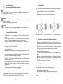
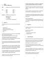
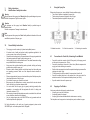
1 = Materialanschluss 2 = Steuerluftanschluss 3 = Zerstäuberluftanschluss
1 2 3
1 2 3

1514
5.1 Luftkopf wechseln
1. Schrauben Sie die Luftkopfmutter ab.
2. Entfernen Sie den Luftkopf (Pos. 1).
5.2 Materialdüse wechseln
1. Schrauben Sie die Luftkopfmutter ab.
2. Entfernen Sie den Luftkopf.
3. Schrauben Sie die Materialdüse (Pos. 2) aus.
Der Einbau geschieht in umgekehrter Reihenfolge.
5.3 Materialnadel wechseln
1. Schrauben Sie die Zugstange (Pos. 22) aus.
2. Schrauben Sie die Regelkappe (Pos. 21) ab.
3. Entfernen Sie die Nadelfeder (Pos. 20).
4. Schrauben Sie die Gewindebuchse (Pos. 19) aus dem Körper.
5. Ziehen Sie die komplette Einheit (Pos. 9 -16), die Nadel (Pos. 17) und den
Kolben (Pos.11) heraus.
6. Ziehen Sie die Nadel aus dem Kolben heraus.
7. Das Einstellmaß, - die Nadelspitze bis zum Kolben - beträgt 79,0 mm.
Der Einbau geschieht in umgekehrter Reihenfolge.
5.4 Nadelpackung wechseln
1. Schrauben Sie das Vorderteil (Pos. 3) vom Kolbengehäuse (Pos. 6) ab.
2. Entfernen Sie die Dichtung (Pos. 25).
3. Bauen Sie die komplette Nadelpackung (Pos. 4) aus. Verwenden Sie hierzu
einen gebogenen Draht.
4. Fetten Sie die neue Nadelpackung leicht ein.
Der Einbau geschieht in umgekehrter Reihenfolge.
4.3 Spritzbild verändern
• Zur Auswahl stehen Rund- oder Breitstrahlköpfe.
• Durch Verändern der Zerstäuberluft wird die Strahlbreite variiert.
Die Materialdurchflussmenge wird durch den Materialdruck und dem Durchmesser
der Materialdüse bestimmt.
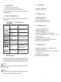
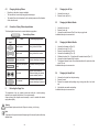
4.4 Mängel eines Spritzbildes beheben
Die folgende Tabelle zeigt Ihnen, mit welchen Einstellungen Sie das Spritzbild beein-
flussen können:
Spritzbildprobe Abweichung erforderliche Einstellung
Spritzbild ist in der Mitte
zu dick
• breitere Spritzstrahlform ein-
stellen
Spritzbild ist an den
Enden zu dick
• rundere Spritzstrahlform ein-
stellen
Spritzbild ist ziemlich
grobtropfig
• Zerstäuberluftdruck erhöhen
Materialauftrag ist in der
Spritzbildmitte sehr dünn
• Zerstäuberluftdruck verringern
Spritzbild ist in der Mitte
gespalten
• Düsendurchmesser erhöhen
• Zerstäuberluftdruck verringern
• Materialdruck erhöhen
Spritzbild ist sehr ballig
• Materialdruck verringern
• Zerstäuberluftdruck erhöhen
5 Spritzautomat umrüsten
Die zum Spritzmaterial passende Luftkopf-, Materialdüse-, Nadelkombination bildet
eine aufeinander abgestimmte Einheit - die Düseneinlage.Tauschen Sie immer die
komplette Düseneinlage aus, damit die gewünschte Spritzbildqualität erhalten bleibt.
Warnung
Unterbrechen Sie vor jeder Umrüstung die Luft- und Materialzufuhr zur Spritzpistole
- Verletzungsgefahr.
Hinweis
Zur Durchführung der im Folgenden aufgeführten Arbeitsschritte benutzen Sie bitte
die Explosionszeichnung am Anfang dieser Betriebsanleitung.
angestrebtes Spritzergebnis

1716
6 Fehlersuche und -beseitigung
Warnung
Schalten Sie vor jeder Instandsetzung die Steuer- und Zerstäuberluft sowie die
Materialzufuhr zur Spritzpistole drucklos - Verletzungsgefahr.
Fehler Ursache Abhilfe
Pistole tropft Materialnadel oder -düse ver-
schmutzt
Materialnadel oder -düse
beschädigt
Ausbauen und reinigen
Austauschen
Pistole öffnet nicht Steuerluftdruck zu niedrig Steuerluftdruck erhöhen
auf min. 4,5 bar
Stoßweiser oder
flatternder
Spritzstrahl
Zu wenig Material im
Spritzbehälter
Material auffüllen
(s. Betriebsanleitung des
Materialherstellers)
Pistole bläst in
Ruhestellung
Topfmanschette (Pos. 7)
beschädigt
Auswechseln
Material sprudelt im
Materialbehälter
Zerstäuberluft gelangt über
Materialkanal in den Material-
behälter.
Materialdüse oder Luftkopf
nicht richtig angezogen
Teile reinigen, anziehen
oder ersetzen
Spritzteil einseitig Hornbohrung am Luftkopf ver-
schmutzt
Ausbauen und reinigen
7 Reinigung und Wartung
• Damit die Lebensdauer und Funktion des Spritzautomaten lange erhalten bleibt,
muss der Spritzautomat regelmäßig gewartet, gereinigt und geschmiert werden.
• Schalten Sie vor jeder Wartung die Steuer- und Zerstäuberluft sowie die
Materialzufuhr zu dem Spritzautomaten drucklos.
• Die Reinigung sollte nach jedem Farb- und Materialwechsel oder je nach
Verschmutzungsgrad erfolgen.
• Verwenden Sie zur Reinigung nur Reinigungsmittel, die vom Hersteller des
Spritzmaterials angegeben werden und die folgenden Bestandteile nicht enthal-
ten:
• Halogenierte Kohlenwasserstoffe (z. B. 1.1.1 Trichlorethan,
Methylen-Chlorid, usw.)
• Säuren und säurehaltige Reinigungsmittel
• Entlackungsmittel
• Regenerierte Lösemittel (Reinigungsverdünnungen)
• Legen Sie den Spritzautomaten nie komplett in Löse- oder Reinigungsmittel. Die
einwandfreie Funktion des Spritzautomaten könnte sonst gefährdet sein.
• Verwenden Sie zur Reinigung keine spitzen oder harten Gegenstände.
Präzisionsteile könnten sonst beschädigt werden und das Spritzergebnis
verschlechtern.
• Für Schäden, die aus einer unsachgemäßen Behandlung herrühren, übernimmt
WALTHER Spritz- und Lackiersysteme keine Gewährleistung.
8 Technische Daten
Gewicht: 360 g
Anschluss:
Zerstäuberluft: G 1/4
Steuerluft: CK 1/8 PK 4
Materialzufuhr: G 3/8
Druckbereich:
Steuerluftdruck: min. 4,5 bar
Materialdruck: max. 8 bar
Zerstäuberluftdruck: max. 8 bar
Schallpegel
(gemessen in
ca. 1 m Abstand
zur Spritzpistole) 83 dB (A)
Luftverbrauch bei:
Eingangsdruck Rundstrahl Breitstrahl
1,0 bar 150 L/min 180 L/min
2,0 bar 210 L/min 260 L/min
3,0 bar 250 L/min 310 L/min
4,0 bar 280 L/min 360 L/min
5,0 bar 310 L/min 400 L/min
6,0 bar 340 L/min 430 L/min
Technische Änderungen vorbehalten.

1918
Contents
Exploded Drawing 4
Declaration of CE-Conformity 19
Replacement parts 20
1 General 22
1.1 Identification of Model Version 22
1.2 Normal Use 22
1.3 Improper use 23
2 Technical Description 23
3 Safety Instructions 24
3.1 Identification of safety instructions 24
3.2 General Safety Instructions 24
4 Using the Spray Gun 25
4.1 Connections for Control Air, Atomising Air and Material 25
4.2 Spraying a Test Pattern 25
4.3 Changing the Spray Pattern 26
4.4 Correction of Spray Pattern Imperfections 26
5 Re-tooling the Spray Gun 26
5.1 Changing the Air Cap 27
5.2 Changing the Material Nozzle 27
5.3 Changing the Material Needle 27
5.4 Changing the Needle Seal 27
6 Troubleshooting 28
7 Cleaning and Maintenance 28
8 Technical Data 29
Declaration of Conformity
We, the manufacturers of the equipment, hereby declare under our sole responsibility
that the product(s) described below conform to the essential safety requirements. This
declaration will be rendered invalid if any changes are made to the equipment without
prior consultation with us.
Manufacturer WALTHER Spritz- und Lackiersysteme GmbH
Kärntner Str. 18 - 30
D - 42327 Wuppertal
Tel.: +49(0)202 / 787 - 0
Fax: +49(0)202 / 787 - 2217
www.walther-pilot.de • e-mail: [email protected]
Type Designation Automatic Spray Gun
PILOT WA 600 / WA 610 / WA 625 / WA 635
WA 600 V 20 600 WA 625 MP V 20 607
WA 610-U V 20 601 WA 635 MP-U V 20 608
Intended purpose Processing of sprayable media
Applied Standards and Directives
EU-Mechanical Engineering Directives 2006/42/EC
2014/34/EU (ATEX Directives)
DIN EN ISO 12100
DIN EN 1953 DIN EN 13463-1
DIN EN 1127-1 DIN EN 13463-5
Specification according 2014/34/EU
Category 2 Part marking II 2 G c T 5
Tech.File,Ref.:
2406
Authorized with the compilation of the technical file:
Nico Kowalski, WALTHER Spritz- und Lackiersysteme GmbH, Kärntner Str. 18 - 30
D- 42327 Wuppertal
Special remarks :
The named product is intended for installation in other equipment. Commissioning is
prohibited until such time as the end product has been proved to conform to the
provision of the Directives 2006/42/EC.
Wuppertal, the 2nd of November 2016
Name: Torsten Bröker
Position: Manager, Design and Development
This Declaration does not give assurance of properties in the sense of product liability. The safety instructions
provided in the product documentation must be observed at all times.
p.p.

2120
Listing of Replacement Parts PILOT WA 600 / WA 610 / WA 625 and WA 635
PILOT WA 600 PILOT WA 610-U
V 20 600 V 20 601
Item Parts No. Qty. Description Qty. Description
1
Air Control Head 0,3 - 1,5 mm ø
1
V 10 151 30 039*
1
V 10 151 30 039*
Air Control Head 1,8 - 2,2 mm ø V 10 151 30 189* V 10 151 30 189*
2 Material Nozzle 1 V 10 151 40 .. 3* 1 V 10 151 40 .. 3*
3 Front Part 1 V 20 410 10 000 1 V 20 420 10 000
4 Needle Packing compl. 1 V 09 001 80 000 1 V 09 001 80 000
5 Connection 1 V 20 310 09 003 1 V 20 310 09 003
6 Piston Casing 1 V 20 410 40 000 1 V 20 410 40 000
7 Cup Seal 1 V 09 220 27 000 1 V 09 220 27 000
8 O-Ring 1 V 09 103 22 001 1 V 09 103 22 001
9 Piston-Boss Bushing 1 V 20 410 24 004 1 V 20 410 24 004
10 O-Ring 1 V 09 102 67 000 1 V 09 102 67 000
11 Piston Bushing 1 V 20 410 23 004 1 V 20 410 23 004
12 Cup seal 1 V 09 220 28 000 1 V 09 220 28 000
13 Clamping Washer 1 V 20 410 18 004 1 V 20 410 18 004
14 O-Ring 1 V 09 102 20 001 1 V 09 102 20 001
15 Pressure Ring 1 V 20 410 39 004 1 V 20 410 39 004
16 Piston Screw 1 V 20 410 16 004 1 V 20 410 16 004
17 Material Needle 1 V 20 410 30 .. 3* 1 V 20 410 30 .. 3*
18 Piston Spring 1 V 20 410 17 000 1 V 20 410 17 000
19 Threaded Ring 1 V 20 410 27 000 1 V 20 410 27 000
20 Needle Spring 1 V 20 410 28 003 1 V 20 410 28 003
21 Cap 1 V 20 410 29 000 1 V 20 410 29 000
22 Threaded Rod compl.. 1 V 20 410 36 000 1 V 20 410 36 000
23 Atomizing Air Connection 1 V 20 410 19 005 1 V 20 410 19 005
24 Control Air Connection 1 V 66 101 53 322 1 V 66 101 53 322
25 Seal 1 V 09 001 81 000 1 V 09 001 81 000
26 Seal 1 V 09 002 51 000 2 V 09 002 51 000
27 Material Connection 1 V 20 410 13 003 2 V 20 410 13 003
28 Hexagonal Screw 3 V 20 410 37 003 3 V 20 410 37 003
29 Round- and Wide-Fan-Adjustment 2 V 20 410 20 000 2 V 20 410 20 000
* Please make sure to quote the required size when placing an order for replacement
parts,diameter: 0.3 • 0.5 • 0.8 • 1.0 • 1.2 • 1.5 • 1.8 • 2.0 • 2.2 mm
We recommend to hold all bold-faced replacement parts on stock.
Listing of Replacement Parts PILOT WA 600 / WA 610 / WA 625 and WA 635
PILOT WA 625-MP PILOT WA 635-MP-U
V 20 607 V 20 608
Item Parts No. Qty. Description Qty. Description
1
Air Control Head 0,3 - 1,5 mm ø
1
V 10 141 30 038
1
V 10 141 30 038
Air Control Head 1,8 - 2,2 mm ø V 10 141 30 188 V 10 141 30 188
2 Material Nozzle 1 V 10 151 40 .. 3* 1 V 10 151 40 ..3*
3 Front Part 1 V 20 410 10 000 1 V 20 420 10 000
4 Needle Packing compl. 1 V 09 001 80 000 1 V 09 001 80 000
5 Connection 1 V 20 310 09 003 1 V 20 310 09 003
6 Piston Casing 1 V 20 410 40 000 1 V 20 410 40 000
7 Cup Seal 1 V 09 220 27 000 1 V 09 220 27 000
8 O-Ring 1 V 09 103 22 001 1 V 09 103 22 001
9 Piston-Boss Bushing 1 V 20 410 24 004 1 V 20 410 24 004
10 O-Ring 1 V 09 102 67 000 1 V 09 102 67 000
11 Piston Bushing 1 V 20 410 23 004 1 V 20 410 23 004
12 Cup seal 1 V 09 220 28 000 1 V 09 220 28 000
13 Clamping Washer 1 V 20 410 18 004 1 V 20 410 18 004
14 O-Ring 1 V 09 102 20 001 1 V 09 102 20 001
15 Pressure Ring 1 V 20 410 39 004 1 V 20 410 39 004
16 Piston Screw 1 V 20 410 16 004 1 V 20 410 16 004
17 Material Needle 1 V 20 410 30 .. 3* 1 V 20 410 30 ..3*
18 Piston Spring 1 V 20 410 17 000 1 V 20 410 17 000
19 Threaded Ring 1 V 20 410 27 000 1 V 20 410 27 000
20 Needle Spring 1 V 20 410 28 003 1 V 20 410 28 003
21 Cap 1 V 20 410 29 000 1 V 20 410 29 000
22 Threaded Rod compl.. 1 V 20 410 36 000 1 V 20 410 36 000
23 Atomizing Air Connection 1 V 20 607 03 005 1 V 20 607 03 005
24 Control Air Connection 1 V 66 101 53 322 1 V 66 101 53 322
25 Seal 1 V 09 001 81 000 1 V 09 001 81 000
26 Seal 1 V 09 002 51 000 2 V 09 002 51 000
27 Material Connection 1 V 20 410 13 003 2 V 20 410 13 003
28 Hexagonal Screw 3 V 20 410 37 003 3 V 20 410 37 003
29 Round- and Wide-Fan-Adjustment 2 V 20 410 20 000 2 V 20 410 20 000
Repair Set No.: V 16 600 02 .. 3
Includes all bold-faced wearing parts

2322
1 General
1.1 Identification of Model Version
Model: Automatic Spray Gun PILOT WA 600 / WA 610 / WA 625 / WA 635
Type: WA 600 V 20 600
WA 610 V 20 601
WA 625 V 20 607
WA 635 V 20 608
Manufacturer: WALTHER Spritz- und Lackiersysteme GmbH
Kärntner Straße 18-30
D-42327 Wuppertal
Tel: +49 202 787-0
Fax: +49 202 787-2217 • www.walther-pilot.de
1.2 Normal Use
The automatic spray gun must be used only for processing sprayable materials, in
particular:
• lacquers and paints
• grease, oil and anti-corrosion agents
• adhesives, grease, oil and anti-corrosion agents
• ceramic glazes
• stains
If you intend to spray materials that are not listed here, please contact WALTHER
Spritz- und Lackiersysteme GmbH, Wuppertal.
The sprayable materials must be sprayed only on workpieces or objects.
The temperature of the material to be sprayed must not exceed 80°C.
The models PILOT WA 600, WA 610, WA 625 and WA 635 are not a hand-held spray
guns and must therefore be mounted in a suitable bracket.
Proper use of the spray gun also includes the fact that you have read, understood and
observed all information, advice and safety requirements presented in this instruction
manual.
This equipment complies with the explosion protection requirements of Directive
2014/34/EU (ATEX) for the explosion group, equipment category and temperature
class indicated on the type plate. When using the equipment, the requirements
specified in these Operating Instructions must be observed at all times.
The technical data indicated on the equipment rating plates and the specifications in
the chapter "Technical Data" must be complied with at all times and must not be
exceeded. An overloading of the equipment must be ruled out.
The equipment may be used in potentially explosive atmospheres only with the
authorisation of the relevant supervisory authority.
The relevant supervisory authority or the operator of the equipment are
responsible for determining the explosion hazard (zone classification).
The operator must check and ensure that all technical data and the marking of the
equipment in accordance with ATEX are compliant with the necessary
requirements.
The operator must provide corresponding safety measures for all applications in
which the breakdown of the equipment might lead to danger to persons.
If any irregularities are observed while the equipment is in operation, the equipment
must be put out of operation immediately and WALTHER Spritz- und Lackiersysteme
must be consulted.
Grounding / Equipotential Bonding
You must ensure that the spray gun is properly earthed (grounded) either separate-
ly or in connection with the equipment with which it is being used (maximum
resistance 10
6
Ω).
1.3 Improper Use
The spray gun must not be used in any other way than as described above in the
section 1.2 Normal Use.
Any other form of use is prohibited.
Improper use includes:
• spraying materials onto persons or animals
• spraying liquid nitrogen
2 Technical Description
The models PILOT WA 600, WA 610, WA 625 and WA 635 are operated automati-
cally by compressed air and is controlled via 3/2-way control valves. Hand-operated,
foot-operated or solenoid-valve-operated valves can be used for this purpose.
First, the atomising air is introduced by a 3/2-way valve.
Then, the 3/2-way control valve required for the control air is actuated.
The compressed air flowing into the cylinder chamber moves the control piston and
opens the material feed.
If the control air is interrupted by the 3/2-way valve, the compressed air in the
cylinder chamber is allowed to escape. The spring pressure of the piston spring
shuts off the material feed to the material nozzle.
After this, the atomising air is switched off by the 3/2-way valve.
Nozzle and needle are made of corrosion-free stainless steel.

2524
3 Safety instructions
3.1 Identification of safety instructions
Warning
The pictogram and the urgency level “Warning“ identify a possible danger to persons.
Possible consequences: Slight to severe injuries.
Attention
The pictogram and the urgency level “Attention“ identify a possible danger to
material assets.
Possible consequences: Damage to material assets.
Note
The pictogram and the urgency level “Note“ identify additional information for the safe
and efficient operation of the spray gun.
3.2 General Safety Instructions
• The spray gun must be used only by trained and qualified persons.
• All relevant rules of safety and workers‘ safety regulations applicable in the
country or area of use must be fully observed.
• Observe the instructions given by the manufacturers of the spraying material and
the cleaning agents with regard to safety and proper use.
• Use the spray gun only in well-ventilated rooms. Fire, naked flames and smoking
are prohibited within the working area.
• Always wear the regulation breathing masks, protective clothing and hearing
protection when using the spray gun.
• Exhaust air which contains particles must be kept away from the working area
and operating personnel. Make sure that adequate exhaust extraction is
provided.
• When spraying materials, keep your hands and other parts of the body away from
the pressurised nozzle of the spray gun.
• Do not direct the spray gun at persons or animals.
• Before carrying out maintenance or servicing, ensure that the air and material
feed to the spray gun have been depressurised.
• You must ensure that the spray gun is properly earthed (grounded) either
separately or in connection with the equipment with which it is being used
(maximum resistance 10
6
Ω).
• After carrying out assembly and maintenance work, ensure that all nuts, bolts and
screw connections have been fully tightened.
• Use only original spare parts, since WALTHER can only guarantee safe and
fault-free operation for original parts.
For further information on the safe use of spraying equipment, please contact
WALTHER Spritz- und Lackiersysteme GmbH, Wuppertal.
4 Using the Spray Gun
Before using the spray gun, ensure that the following conditions apply:
• The control air pressure is applied to the spray gun
• The atomising air pressure is applied to the spray gun
• The material pressure is applied to the spray gun
4.1 Connections for Control Air, Atomising Air and Material
• Connect the control air connector (via the 3/2-way valve) to the spray gun and
set the control air pressure (min. 4,5 bar).
• Connect the atomising air connector to the air hose (filtered compressed air
supply) and to the atomising air connection.
• Switch on the compressed air and set the required atomising air pressure at the
reducing valve (max. 8 bar).
• Fill the pressure pot with the material to be sprayed and close the lid.
• Connect the material feed hose to the pressure pot or the pump and to the
material connection. Set the required material pressure (max. 8 bar).
• Open the material valve on the pressure pot.
4.2 Spraying a Test Pattern
A test spray pattern should always be made whenever:
• the spray gun is used for the first time
• the spraying material is changed
• the spray gun has been disassembled for maintenance or servicing.
The test pattern can be sprayed on a test workpiece, panel, cardboard or paper.
1 2 3
1 = Material connection 2 = Control air connection 3 = Atomizing air connection
1 2 3

2726
5.1 Changing the Air Cap
1. Unscrew the air cap nut.
2. Remove the air cap (Pos.1).
5.2 Changing the Material Nozzle
1. Unscrew the air cap nut.
2. Remove the air cap.
3. Unscrew the material nozzle (Pos.2) from the spray gun head.
Installation takes place in reverse order.
5.3 Changing the Material Needle
1. Unscrew the threaded rod (Pos. 22).
2. Unscrew the air cap (Pos. 21).
3. Remove the needle spring (Pos 20).
4. Unscrew the threaded ring (Pos. 19).
5. Withdraw the piston (Pos. 11) together with the material needle (Pos. 17).
6. Unscrew the material needle from the piston.
7. The distance between the tip of the material needle and the piston should be
set at 79,0 mm.
Installation takes place in reverse order.
5.4 Changing the Needle Seal
1. Unscrew the front part from the piston casing.
2. Remove the seal.
3. Remove the complete needle packing using a strong wire with a hook at its
end.
4. Lubricate the new needle seal packing..
Installation takes place in reverse order.
4.3 Changing the Spray Pattern
• Round-fan or wide-fan air caps are available.
• The fan width can be varied by changing the atomising air.
• The material flow rate is determined by the material pressure and the diameter
of the material nozzle.
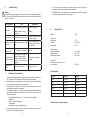
4.4 Correction of Spray Pattern Imperfections
The following table shows how to correct a defective spray pattern.
Spray pattern
test
Fault Necessary adjustment
Swollen centre • Spray jet should be flatter
Swollen ends • Spray jet should be rounder
Coarse pearl effect • Increase atomising air pressure
Unduly thin paint layer in
centre
• Decrease atomising air pressu-
re
Split centre
• Increase nozzle diameter
• Reduce atomising air pressure
• Increase material pressure
Very spherical
• Decrease material pressure
• Increase atomising air pressure
5 Re-tooling the Spray Gun
The combination of air cap, material nozzle and needle for a certain spraying
material forms a specially matched unit - the nozzle assembly.
Always exchange the complete nozzle assembly in order to maintain the desired
spray pattern quality.
Warning
Air and material inputs must be shut off prior to re-tooling - risk of injury.
Note
Please refer to the exploded view at the beginning of this manual to perform the steps
detailed below.
Desired Spray Pattern

2928
6 Troubleshooting
Warning
Prior to any servicing and repair work the spray gun should be inunpressurised state,
i.e. all control air and atomising air pressure as well as all material inputs must be
shut off - risk of injury.
Spray pattern Fault Adjustment
Gun drips
Material needle or nozzle dirty
Material needle or nozzle
damaged
Remove and clean
Replace
Gun does not open Control air pressure too low
Increase control air pressu-
re to min. 4.5 bar
Irregular or splatte-
ring spray
Insufficient material in contai-
ner
Fill up with material (see
instructions from material
manufacturer)
Gun sprays when
switched off
Cup Seal (Item 7) damaged Replace
Material bubbling in
material container
Atomising air is entering the
material container via the
material channel. Material
nozzle or air cap not properly
tightened
Clean the parts, tighten or
replace
Spray fan one-
sided
Air cap horn bore dirty Remove and clean
7 Cleaning and maintenance
• To ensure that the spray gun functions properly and to maximise its service life,
the spray gun must be maintained, cleaned and lubricated regularly.
• Before carrying out any maintenance, ensure that the control air and atomising
air as well as the material feed are depressurised.
• Cleaning should be carried out after every colour and material change or
according to the degree of contamination.
• For cleaning the spray gun, use only those cleaning agents that are specified by
the material manufacturer and ensure that they do not contain any of the
following components:
• halogenated hydrocarbons,( e.g. 1,1,1-trichloroethane, methylene
chloride,etc.)
• acids or acidic cleaning agents,
• paint strippers,
• regenerated solvents (cleaning thinners).
• Never immerse the whole spray gun in solvent or cleaning agent, as this could
harm the correct functioning of the gun.
• Do not use sharp or hard objects to clean the spray gun, as this might cause
damage to precision parts and impair the spraying result.
• WALTHER Spritz- und Lackiersysteme cannot accept any liability for damage
caused by improper treatment of the spray gun.
8 Technical Data
Weight: 360 g
Connections
Atomising air: G 1/4
Control air CK 1/8 PK 4
Material feed: G 3/8
Pressure range:
Control air pressure: min. 4,5 bar
Material pressure: max. 8 bar
Atomising air pressure: max. 8 bar
Noise Level
(measured at a distance of ca. 1 m
from spray gun) 83 dB (A)
Air Consumption:
Air input Round fan Wide fan
1,0 bar 150 L/min 180 L/min
2,0 bar 210 L/min 260 L/min
3,0 bar 250 L/min 310 L/min
4,0 bar 280 L/min 360 L/min
5,0 bar 310 L/min 400 L/min
6,0 bar 340 L/min 430 L/min
Technical data are subject to change.

Das WALTHER PILOT - Programm
• Hand-Spritzpistolen
• Automatik-Spritzpistolen
• Niederdruck-Spritzpistolen
(System HVLP)
• Zweikomponenten-Spritzpistolen
• Materialdruckbehälter
• Drucklose Behälter
• Rührwerk-Systeme
• Airless-Geräte und Flüssigkeitspumpen
• Materialumlaufsysteme
• 2-K - Anlagen
• Signieranlagen
• Kombinierte Spritz- und Trockenboxen
• Absaugsysteme mit
Trockenabscheidung
• Absaugsysteme mit Nassabscheidung
• Kleberspritzsysteme
• Trockner
• Zuluft-Systeme
• Atemschutz-Systeme und Zubehör
The WALTHER PILOT Product Range
• Manual spray guns
• Automatic spray guns
• HVLP spray guns
• Two-component spray guns
• Pressure containers
• Nonpressurized containers
• Agitator systems
• Airless equipment and fluid pumps
• Material circulation systems
• Two-pack systems
• Marking equipment
• Combined spraying and drying booths
• Spray booths with dry filtering
• Spray booths with wet filtering
• Adhesive spraying systems
• Dryers
• Air regulators / air filters
• Health protection equipment
Walther Spritz- und Lackiersysteme GmbH
Kärntner Straße 18 -30
.
D-42327 Wuppertal
T +49 202 787-0
.
F +49 202 787-2217
info@walther-pilot.de
.
www.walther-pilot.de
Technische Änderungen und Irrtümer vorbehalten. © WALTHER PILOT 12/2016
-
 1
1
-
 2
2
-
 3
3
-
 4
4
-
 5
5
-
 6
6
-
 7
7
-
 8
8
-
 9
9
-
 10
10
-
 11
11
-
 12
12
-
 13
13
-
 14
14
-
 15
15
-
 16
16


WALTHER PILOT PILOT WA 600 Bedienungsanleitung
- Kategorie
- Power-Feinsprühsysteme
- Typ
- Bedienungsanleitung
in anderen Sprachen
Verwandte Papiere
-
WALTHER PILOT V 20 340 Bedienungsanleitung
-
-
-
-
-
-
-
-
-