MSI B450M PRO-VDH MAX Benutzerhandbuch
- Kategorie
- Motherboards
- Typ
- Benutzerhandbuch

1
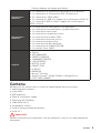
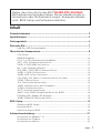
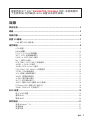
< 1> Contents
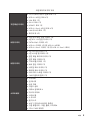
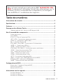
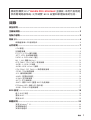
Contents
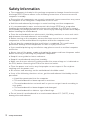
Safety Information ........................................................................................... 2
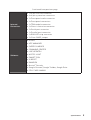
Specifications ...................................................................................................3
Package contents ............................................................................................6
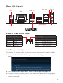
Rear I/O Panel .................................................................................................7
LAN Port LED Status Table .................................................................................7
Overview of Components ................................................................................8
CPU Socket .........................................................................................................9
DIMM Slots ........................................................................................................10
PCI_E1~3: PCIe Expansion Slots ......................................................................11
JFP1, JFP2: Front Panel Connectors ...............................................................12
SATA1~4: SATA 6Gb/s Connectors....................................................................12
M2_1: M.2 Slot (Key M) .....................................................................................13
ATX_PWR1, CPU_PWR1: Power Connectors....................................................13
JUSB1~2: USB 2.0 Connectors .........................................................................14
JUSB3: USB 3.2 Gen1 Connector .....................................................................14
CPU_FAN1, SYS_FAN1~2: Fan Connectors ......................................................15
JTPM1: TPM Module Connector .......................................................................16
JCI1: Chassis Intrusion Connector ...................................................................16
JAUD1: Front Audio Connector ......................................................................... 17
JCOM1: Serial Port Connector .........................................................................17
JLPT1: Parallel Port Connector........................................................................17
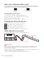
JBAT1: Clear CMOS (Reset BIOS) Jumper .......................................................18
EZ Debug LED: Debug LED indicators ..............................................................18
JRGB1: RGB LED strip connector .....................................................................18
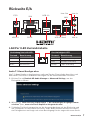
BIOS Setup ..................................................................................................... 19
Entering BIOS Setup .........................................................................................19
Resetting BIOS ..................................................................................................20
Updating BIOS ...................................................................................................20
Software Description .....................................................................................21
Installing Windows
®
10 .....................................................................................21
Installing Drivers ..............................................................................................21
Installing Utilities ..............................................................................................22
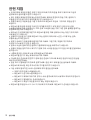
Thank you for purchasing the MSI
®
B450M PRO-VDH MAX
motherboard. This User Guide gives information about
board layout, component overview, BIOS setup and software
installation.
Seite wird geladen ...
Seite wird geladen ...

4
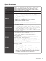
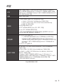
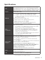
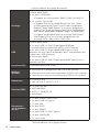
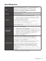
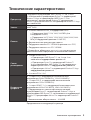
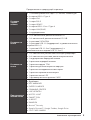
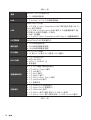
Specifications
Continued from previous page
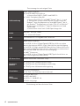
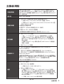
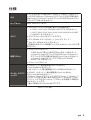
Audio
Realtek
®
ALC892 Codec
y 7.1-Channel High Definition Audio
LAN 1x Realtek
®
8111H Gigabit LAN controller
USB
AMD
®
B450 Chipset
y 2x USB 3.2 Gen1 (SuperSpeed USB) ports through the
internal USB 3.2 Gen1 connector
y 8x USB 2.0 (High-speed USB) ports (4 ports on the back
panel, 4 ports available through the internal USB connectors)
y AMD
®
processor
y 4x USB 3.2 Gen1 (SuperSpeed USB) Type-A ports on the
back panel
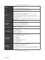
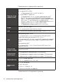
I/O Controller NUVOTON 6795D Controller Chip
Hardware
Monitor
y CPU/System temperature detection
y CPU/System fan speed detection
y CPU/System fan speed control
Form Factor
y m-ATX Form Factor
y 9.6 in. x 9.6 in. (24.4 cm x 24.4 cm)
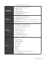
BIOS Features
y 1x 256 Mb flash
y UEFI AMI BIOS
y ACPI 6.1, SM BIOS 2.8
y Multi-language
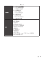
Back Panel
Connectors
y 1x PS/2 keyboard/ mouse combo port
y 4x USB 2.0 Type-A ports
y 1x VGA port
y 1x DVI-D port
y 1x HDMI™ port
y 4x USB 3.2 Gen1 Type-A ports
y 1x LAN (RJ45) port
y 3x audio jacks
Internal
Connectors
y 1x 24-pin ATX main power connector
y 1x 8-pin ATX 12V power connector
y 4x SATA 6Gb/s connectors
y 2x USB 2.0 connectors (supports additional 4 USB 2.0 ports)
y 1x USB 3.2 Gen1 connector (supports additional 2 USB 3.2
Gen1 ports)
Continued on next page
Seite wird geladen ...

6
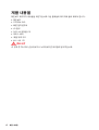
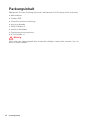
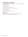
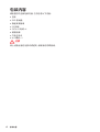
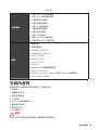
Package contents
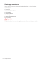
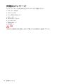
Package contents
Please check the contents of your motherboard package. It should contain:
y Motherboard
y Driver DVD
y Quick Installation Guide
y I/O Shielding
y SATA 6G Cable x2
y Case Badge
y Product registration card
y M.2 Screw x1
Important
If any of the above items are damaged or missing, please contact your retailer.
Seite wird geladen ...

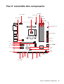
8
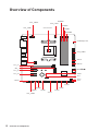
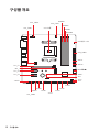
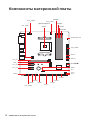
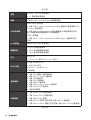
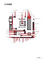
Overview of Components
CPU_FAN1
CPU SocketSYS_FAN1
PCI_E3
JAUD1
PCI_E2
M2_1
PCI_E1
DIMMA1
DIMMA2
DIMMB1
DIMMB2
JBAT1
JCI1
JFP2
JFP1
JUSB3
ATX_PWR1
CPU_PWR1
EZ Debug LED
SATA2
SATA1
JTPM1
JUSB1
JLPT1
JRGB1
JUSB2
JCOM1
SYS_FAN2
SATA34
Overview of Components
Seite wird geladen ...

10
Overview of Components
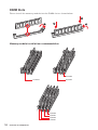
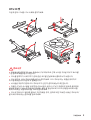
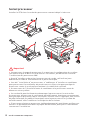
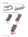
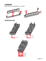
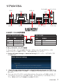
DIMM Slots
Please install the memory module into the DIMM slot as shown below.
1
2
3
2
Memory module installation recommendation
DIMMB2
DIMMA2 DIMMA2
DIMMB2
DIMMB1
DIMMA2
DIMMA1
Seite wird geladen ...

12
Overview of Components
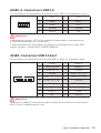
SATA1~4: SATA 6Gb/s Connectors
These connectors are SATA 6Gb/s interface ports. Each connector can connect to one
SATA device.
SATA3
SATA4
SATA2
SATA1
Important
y
Please do not fold the SATA cable at a 90-degree angle. Data loss may result during
transmission otherwise.
y
SATA cables have identical plugs on either sides of the cable. However, it is
recommended that the flat connector be connected to the motherboard for space
saving purposes.
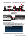
JFP1, JFP2: Front Panel Connectors
These connectors connect to the switches and LEDs on the front panel.
1
2 10
9
+
+
+-
--
-
+
Power LED
HDD LED Reset Switch
Reserved
Power Switch
1 HDD LED + 2 Power LED +
3 HDD LED - 4 Power LED -
5 Reset Switch 6 Power Switch
7 Reset Switch 8 Power Switch
9 Reserved 10 No Pin
JFP2
1
+
+
-
-
Speaker
Buzzer
1 Speaker - 2 Buzzer +
3 Buzzer - 4 Speaker +
HDD LED
RESET SW
HDD LED
HDD LED -
HDD LED +
POWER LED -
POWER LED +
POWER LED
JFP1

13
Overview of Components Overview of Components
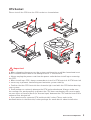
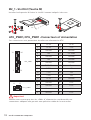
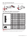
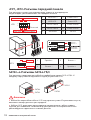
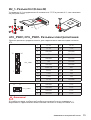
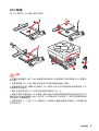
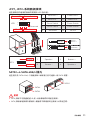
ATX_PWR1, CPU_PWR1: Power Connectors
These connectors allow you to connect an ATX power supply.
Important
Make sure that all the power cables are securely connected to a proper ATX power
supply to ensure stable operation of the motherboard.
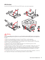
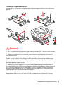
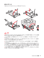
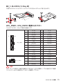
M2_1: M.2 Slot (Key M)
Please install the M.2 solid-state drive (SSD) into the M.2 slot as shown below.
1
2
3
4
5
30
24
131
12
ATX_PWR1
1 +3.3V 13 +3.3V
2 +3.3V 14 -12V
3 Ground 15 Ground
4 +5V 16 PS-ON#
5 Ground 17 Ground
6 +5V 18 Ground
7 Ground 19 Ground
8 PWR OK 20 Res
9 5VSB 21 +5V
10 +12V 22 +5V
11 +12V 23 +5V
12 +3.3V 24 Ground
5
4
1
8
CPU_PWR1
1 Ground 5 +12V
2 Ground 6 +12V
3 Ground 7 +12V
4 Ground 8 +12V

14
Overview of Components
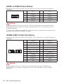
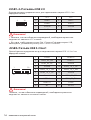
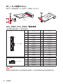
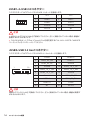
JUSB3: USB 3.2 Gen1 Connector
This connector allows you to connect USB 3.2 Gen1 ports on the front panel.
1 10
1120
1 Power 11 USB2.0+
2 USB3_RX_DN 12 USB2.0-
3 USB3_RX_DP 13 Ground
4 Ground 14 USB3_TX_C_DP
5 USB3_TX_C_DN 15 USB3_TX_C_DN
6 USB3_TX_C_DP 16 Ground
7 Ground 17 USB3_RX_DP
8 USB2.0- 18 USB3_RX_DN
9 USB2.0+ 19 Power
10 NC 20 No Pin
Important
Note that the Power and Ground pins must be connected correctly to avoid possible
damage.
JUSB1~2: USB 2.0 Connectors
These connectors allow you to connect USB 2.0 ports on the front panel.
Important
y
Note that the VCC and Ground pins must be connected correctly to avoid possible
damage.
y
In order to recharge your iPad,iPhone and iPod through USB ports, please install
MSI
®
SUPER CHARGER utility.
1
2 10
9
1 VCC 2 VCC
3 USB0- 4 USB1-
5 USB0+ 6 USB1+
7 Ground 8 Ground
9 No Pin 10 NC

15
Overview of Components Overview of Components
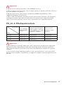
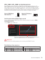
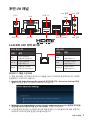
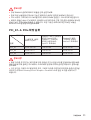
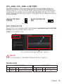
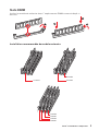
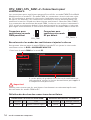
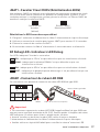
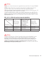
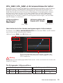
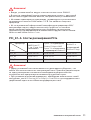
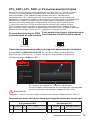
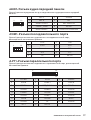
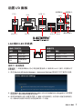
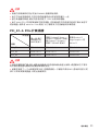
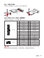
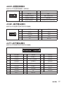
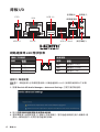
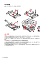
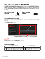
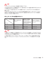
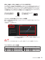
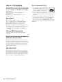
CPU_FAN1, SYS_FAN1~2: Fan Connectors
Fan connectors can be classified as PWM (Pulse Width Modulation) Mode or DC
Mode. PWM Mode fan connectors provide constant 12V output and adjust fan speed
with speed control signal. DC Mode fan connectors control fan speed by changing
voltage. When you plug a 3-pin (Non-PWM) fan to a fan connector in PWM mode, the
fan speed will always maintain at 100%, which might create a lot of noise. You can
follow the instruction below to adjust the fan connector to PWM or DC Mode.
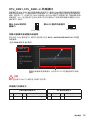
Switching fan mode and adjusting fan speed
You can switch between PWM mode and DC mode and adjust fan speed in BIOS >
HARDWARE MONITOR.
Select PWM mode or DC mode
Important
Make sure fans are working properly after switching the PWM/ DC mode.
There are gradient points of the fan speed that allow you to
adjust fan speed in relation to CPU temperature.
Default PWM Mode
fan connector
Default DC Mode fan
connector
1
CPU_FAN1
1
SYS_FAN1/ 2
PWM Mode pin definition
1 Ground 2 +12V
3 Sense 4 Speed Control Signal
DC Mode pin definition
1 Ground 2 Voltage Control
3 Sense 4 NC
Pin definition of fan connectors

16
Overview of Components
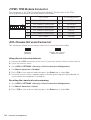
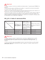
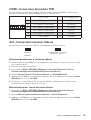
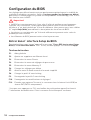
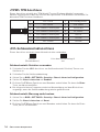
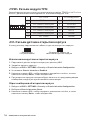
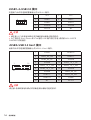
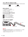
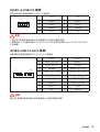
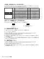
JTPM1: TPM Module Connector
This connector is for TPM (Trusted Platform Module). Please refer to the TPM
security platform manual for more details and usages.
1
2 14
13
1 LPC Clock 2 3V Standby power
3 LPC Reset 4 3.3V Power
5 LPC address & data pin0 6 Serial IRQ
7 LPC address & data pin1 8 5V Power
9 LPC address & data pin2 10 No Pin
11 LPC address & data pin3 12 Ground
13 LPC Frame 14 Ground
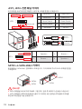
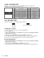
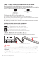
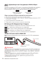
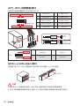
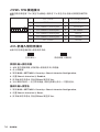
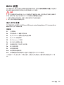
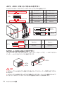
JCI1: Chassis Intrusion Connector
This connector allows you to connect the chassis intrusion switch cable.
Normal
(default)
Trigger the chassis
intrusion event
Using chassis intrusion detector
1. Connect the JCI1 connector to the chassis intrusion switch/ sensor on the chassis.
2. Close the chassis cover.
3. Go to BIOS > SETTINGS > Security > Chassis Intrusion Configuration.
4. Set Chassis Intrusion to Enabled.
5. Press F10 to save and exit and then press the Enter key to select Yes.
6. Once the chassis cover is opened again, a warning message will be displayed on
screen when the computer is turned on.
Resetting the chassis intrusion warning
1. Go to BIOS > SETTINGS > Security > Chassis Intrusion Configuration.
2. Set Chassis Intrusion to Reset.
3. Press F10 to save and exit and then press the Enter key to select Yes.

17
Overview of Components Overview of Components
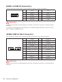
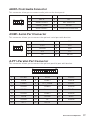
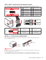
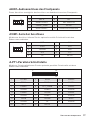
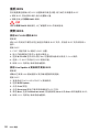
JAUD1: Front Audio Connector
This connector allow you to connect audio jacks on the front panel.
1
2 10
9
1 MIC L 2 Ground
3 MIC R 4 NC
5 Head Phone R 6 MIC Detection
7 SENSE_SEND 8 No Pin
9 Head Phone L 10 Head Phone Detection
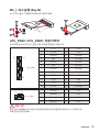
JCOM1: Serial Port Connector
This connector allows you to connect the optional serial port with bracket.
1
2 10
9
1 DCD 2 SIN
3 SOUT 4 DTR
5 Ground 6 DSR
7 RTS 8 CTS
9 RI 10 No Pin
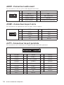
1
2 26
25
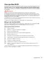
1 RSTB# 2 AFD# 3 PRND0
4 ERR# 5 PRND1 6 PINIT#
7 PRND2 8 LPT_SLIN# 9 PRND3
10 Ground 11 PRND4 12 Ground
13 PRND5 14 Ground 15 PRND6
16 Ground 17 PRND7 18 Ground
19 ACK# 20 Ground 21 BUSY
22 Ground 23 PE 24 Ground
25 SLCT 26 No Pin
JLPT1: Parallel Port Connector
This connector allows you to connect the optional parallel port with bracket.
Seite wird geladen ...
Seite wird geladen ...
Seite wird geladen ...
Seite wird geladen ...
Seite wird geladen ...
Seite wird geladen ...
Seite wird geladen ...
Seite wird geladen ...
Seite wird geladen ...
Seite wird geladen ...
Seite wird geladen ...
Seite wird geladen ...

8
CPU_FAN1
CPU SYS_FAN1
PCI_E3
JAUD1
PCI_E2
M2_1
PCI_E1
DIMMA1
DIMMA2
DIMMB1
DIMMB2
JBAT1
JCI1
JFP2
JFP1
JUSB3
ATX_PWR1
CPU_PWR1
EZ LED
SATA2
SATA1
JTPM1
JUSB1
JLPT1
JRGB1
JUSB2
JCOM1
SYS_FAN2
SATA34
Seite wird geladen ...

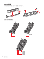
10
DIMM
DIMM .
1
2
3
2
()
DIMMB2
DIMMA2 DIMMA2
DIMMB2
DIMMB1
DIMMA2
DIMMA1
Seite wird geladen ...

12
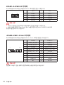
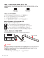
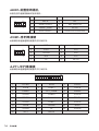
SATA1~4: SATA 6Gb/s
SATA 6Gb/s . SATA
.
SATA3
SATA4
SATA2
SATA1
y
SATA 90 . , .
y
SATA
.
JFP1, JFP2:
LED .
1
2 10
9
+
+
+-
--
-
+
LED
HDD LED
Reserved
JFP1
1 HDD LED + 2 Power LED +
3 HDD LED - 4 Power LED -
5 Reset Switch 6 Power Switch
7 Reset Switch 8 Power Switch
9 Reserved 10 No Pin
JFP2
1
+
+
-
-
Speaker
Buzzer
1 Speaker - 2 Buzzer +
3 Buzzer - 4 Speaker +
HDD LED
RESET SW
HDD LED
HDD LED -
HDD LED +
POWER LED -
POWER LED +
POWER LED
JFP1

13
ATX_PWR1, CPU_PWR1:
ATX .
ATX
.
M2_1: M.2 (Key M)
M.2 (SSD) M.2 .
1
2
3
4
5
30
24
131
12
ATX_PWR1
1 +3.3V 13 +3.3V
2 +3.3V 14 -12V
3 Ground 15 Ground
4 +5V 16 PS-ON#
5 Ground 17 Ground
6 +5V 18 Ground
7 Ground 19 Ground
8 PWR OK 20 Res
9 5VSB 21 +5V
10 +12V 22 +5V
11 +12V 23 +5V
12 +3.3V 24 Ground
5
4
1
8
CPU_PWR1
1 Ground 5 +12V
2 Ground 6 +12V
3 Ground 7 +12V
4 Ground 8 +12V

14
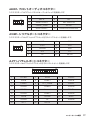
JUSB3: USB 3.2 Gen1
USB 3.2 Gen1 .
1 10
1120
1 Power 11 USB2.0+
2 USB3_RX_DN 12 USB2.0-
3 USB3_RX_DP 13 Ground
4 Ground 14 USB3_TX_C_DP
5 USB3_TX_C_DN 15 USB3_TX_C_DN
6 USB3_TX_C_DP 16 Ground
7 Ground 17 USB3_RX_DP
8 USB2.0- 18 USB3_RX_DN
9 USB2.0+ 19 Power
10 NC 20 No Pin
.
JUSB1~2: USB 2.0
USB 2.0 .
y
VCC .
y
USB iPad,iPhone iPod MSI
®
SUPER CHARGER
.
1
2 10
9
1 VCC 2 VCC
3 USB0- 4 USB1-
5 USB0+ 6 USB1+
7 Ground 8 Ground
9 No Pin 10 NC
Seite wird geladen ...

16
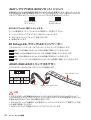
JTPM1: TPM
TPM (Trusted Platform Module) .
TPM .
1
2 14
13
1 LPC Clock 2 3V Standby power
3 LPC Reset 4 3.3V Power
5 LPC address & data pin0 6 Serial IRQ
7 LPC address & data pin1 8 5V Power
9 LPC address & data pin2 10 No Pin
11 LPC address & data pin3 12 Ground
13 LPC Frame 14 Ground
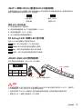
JCI1:
.
( )
1. JCI1 / .
2. .
3. BIOS > SETTINGS () > Security() > Chassis Intrusion Configuration(
) .
4. Chassis Intrusion( ) Enabled() .
5. F10 . Enter Yes .
6. .
1. BIOS > SETTINGS () > Security() > Chassis Intrusion Configuration(
) .
2. Chassis Intrusion( ) Reset() .
3. F10 . Enter Yes .

17
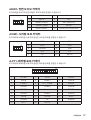
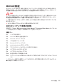
JAUD1:
.
1
2 10
9
1 MIC L 2 Ground
3 MIC R 4 NC
5 Head Phone R 6 MIC Detection
7 SENSE_SEND 8 No Pin
9 Head Phone L 10 Head Phone Detection
JCOM1:
.
1
2 10
9
1 DCD 2 SIN
3 SOUT 4 DTR
5 Ground 6 DSR
7 RTS 8 CTS
9 RI 10 No Pin
1
2 26
25
1 RSTB# 2 AFD# 3 PRND0
4 ERR# 5 PRND1 6 PINIT#
7 PRND2 8 LPT_SLIN# 9 PRND3
10 Ground 11 PRND4 12 Ground
13 PRND5 14 Ground 15 PRND6
16 Ground 17 PRND7 18 Ground
19 ACK# 20 Ground 21 BUSY
22 Ground 23 PE 24 Ground
25 SLCT 26 No Pin
JLPT1:
.
Seite wird geladen ...
Seite wird geladen ...
Seite wird geladen ...
Seite wird geladen ...
Seite wird geladen ...
Seite wird geladen ...
Seite wird geladen ...
Seite wird geladen ...

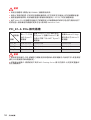
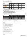
4
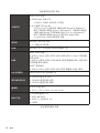
Spécifications
Suite du tableau de la page précédente
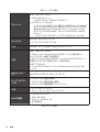
Stockage
Chipset AMD
®
B450
y 4 x ports SATA 6Gb/s
Support des architectures RAID 0, RAID1 et RAID 10
y 1 x slot M.2 (Touche M)
Support PCIe 3.0 x 4 (AMD Ryzen™ de 1ère, 2ème
et 3ème génération/ Ryzen™ avec cœurs graphiques
Radeon™ Vega/ AMD Ryzen™ avec cœurs graphiques
Radeon™ de 2ème génération) ou PCIe 3.0 x2 (Athlon™
avec cœurs graphiques Radeon™ Vega ) et SATA 6Gb/s
Support des périphériques de stockage 2242/ 2260/
2280 Support PCIe 3.0 x4 et des périphériques de
stockage SATA 6 Gb/s 2242/ 2260/ 2280
USB
Chipset AMD
®
B450
y 2 x ports USB 3.2 Gen1 (SuperSpeed USB) par
lintermédiaire du connecteur USB 3.2 Gen1 interne
y 8 x ports USB 2.0 (High-speed USB) (4 ports sur le
panneau arrière, 4 ports disponibles par lintermédiaire des
connecteurs USB internes)
y Processeur AMD
®
y 4 x ports USB 3.2 Gen1 (SuperSpeed USB) Type-A sur le
panneau arrière
Contrôleur E/S Contrôleur NUVOTON 6795D
Moniteur
système
y Détection de la température du CPU et du système
y Détection de la vitesse du ventilateur du CPU et du système
y Contrôle de la vitesse du ventilateur du CPU et du système
Dimensions
y Format m-ATX
y 24,4 cm x 24,4 cm (9,6 x 9,6)
Fonctions BIOS
y 1 x flash 256 Mb
y UEFI AMI BIOS
y ACPI 6.1, SM BIOS 2.8
y Multilingue
Connecteurs
sur le panneau
arrière
y 1 x port clavier/ souris PS/2
y 4 x ports USB 2.0 Type-A
y 1 x port VGA
y 1 x port DVI-D
y 1 x port HDMI™
y 4 x ports USB 3.2 Gen1 Type-A
y 1 x port LAN (RJ45)
y 3 x jacks audio
Suite du tableau sur la page suivante
Seite wird geladen ...
Seite wird geladen ...

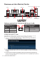
7
Panneau arrière Entrée/ Sortie Vue densemble des composants
CPU_FAN1
Socket
processeur
SYS_FAN1
PCI_E3
JAUD1
PCI_E2
M2_1
PCI_E1
DIMMA1
DIMMA2
DIMMB1
DIMMB2
JBAT1
JCI1
JFP2
JFP1
JUSB3
ATX_PWR1
CPU_PWR1
EZ Debug LED
SATA2
SATA1
JTPM1
JUSB1
JLPT1
JRGB1
JUSB2
JCOM1
SYS_FAN2
SATA34
Vue densemble des composants
Seite wird geladen ...
Seite wird geladen ...
Seite wird geladen ...
Seite wird geladen ...
Seite wird geladen ...
Seite wird geladen ...
Seite wird geladen ...
Seite wird geladen ...
Seite wird geladen ...
Seite wird geladen ...
Seite wird geladen ...
Seite wird geladen ...
Seite wird geladen ...
Seite wird geladen ...
Seite wird geladen ...
Seite wird geladen ...
Seite wird geladen ...
Seite wird geladen ...
Seite wird geladen ...
Seite wird geladen ...
Seite wird geladen ...
Seite wird geladen ...
Seite wird geladen ...
Seite wird geladen ...
Seite wird geladen ...
Seite wird geladen ...
Seite wird geladen ...
Seite wird geladen ...
Seite wird geladen ...
Seite wird geladen ...
Seite wird geladen ...
Seite wird geladen ...
Seite wird geladen ...
Seite wird geladen ...
Seite wird geladen ...
Seite wird geladen ...
Seite wird geladen ...
Seite wird geladen ...
Seite wird geladen ...
Seite wird geladen ...
Seite wird geladen ...
Seite wird geladen ...
Seite wird geladen ...
Seite wird geladen ...
Seite wird geladen ...
Seite wird geladen ...
Seite wird geladen ...
Seite wird geladen ...
Seite wird geladen ...
Seite wird geladen ...
Seite wird geladen ...
Seite wird geladen ...
Seite wird geladen ...
Seite wird geladen ...
Seite wird geladen ...
Seite wird geladen ...
Seite wird geladen ...
Seite wird geladen ...
Seite wird geladen ...
Seite wird geladen ...
Seite wird geladen ...
Seite wird geladen ...
Seite wird geladen ...
Seite wird geladen ...
Seite wird geladen ...
Seite wird geladen ...
Seite wird geladen ...
Seite wird geladen ...
Seite wird geladen ...
Seite wird geladen ...
Seite wird geladen ...
Seite wird geladen ...
Seite wird geladen ...
Seite wird geladen ...
Seite wird geladen ...
Seite wird geladen ...
Seite wird geladen ...
Seite wird geladen ...
Seite wird geladen ...
Seite wird geladen ...
Seite wird geladen ...
Seite wird geladen ...
Seite wird geladen ...
Seite wird geladen ...
Seite wird geladen ...
Seite wird geladen ...
Seite wird geladen ...
Seite wird geladen ...
Seite wird geladen ...
Seite wird geladen ...
Seite wird geladen ...
Seite wird geladen ...
Seite wird geladen ...
Seite wird geladen ...
Seite wird geladen ...
Seite wird geladen ...
Seite wird geladen ...
Seite wird geladen ...
Seite wird geladen ...
Seite wird geladen ...
Seite wird geladen ...
Seite wird geladen ...
Seite wird geladen ...
Seite wird geladen ...
Seite wird geladen ...
Seite wird geladen ...
Seite wird geladen ...
Seite wird geladen ...
Seite wird geladen ...
Seite wird geladen ...
Seite wird geladen ...
Seite wird geladen ...
Seite wird geladen ...
Seite wird geladen ...
Seite wird geladen ...
Seite wird geladen ...
Seite wird geladen ...
Seite wird geladen ...
Seite wird geladen ...
Seite wird geladen ...
Seite wird geladen ...
Seite wird geladen ...
Seite wird geladen ...
Seite wird geladen ...
Seite wird geladen ...
Seite wird geladen ...
-
 1
1
-
 2
2
-
 3
3
-
 4
4
-
 5
5
-
 6
6
-
 7
7
-
 8
8
-
 9
9
-
 10
10
-
 11
11
-
 12
12
-
 13
13
-
 14
14
-
 15
15
-
 16
16
-
 17
17
-
 18
18
-
 19
19
-
 20
20
-
 21
21
-
 22
22
-
 23
23
-
 24
24
-
 25
25
-
 26
26
-
 27
27
-
 28
28
-
 29
29
-
 30
30
-
 31
31
-
 32
32
-
 33
33
-
 34
34
-
 35
35
-
 36
36
-
 37
37
-
 38
38
-
 39
39
-
 40
40
-
 41
41
-
 42
42
-
 43
43
-
 44
44
-
 45
45
-
 46
46
-
 47
47
-
 48
48
-
 49
49
-
 50
50
-
 51
51
-
 52
52
-
 53
53
-
 54
54
-
 55
55
-
 56
56
-
 57
57
-
 58
58
-
 59
59
-
 60
60
-
 61
61
-
 62
62
-
 63
63
-
 64
64
-
 65
65
-
 66
66
-
 67
67
-
 68
68
-
 69
69
-
 70
70
-
 71
71
-
 72
72
-
 73
73
-
 74
74
-
 75
75
-
 76
76
-
 77
77
-
 78
78
-
 79
79
-
 80
80
-
 81
81
-
 82
82
-
 83
83
-
 84
84
-
 85
85
-
 86
86
-
 87
87
-
 88
88
-
 89
89
-
 90
90
-
 91
91
-
 92
92
-
 93
93
-
 94
94
-
 95
95
-
 96
96
-
 97
97
-
 98
98
-
 99
99
-
 100
100
-
 101
101
-
 102
102
-
 103
103
-
 104
104
-
 105
105
-
 106
106
-
 107
107
-
 108
108
-
 109
109
-
 110
110
-
 111
111
-
 112
112
-
 113
113
-
 114
114
-
 115
115
-
 116
116
-
 117
117
-
 118
118
-
 119
119
-
 120
120
-
 121
121
-
 122
122
-
 123
123
-
 124
124
-
 125
125
-
 126
126
-
 127
127
-
 128
128
-
 129
129
-
 130
130
-
 131
131
-
 132
132
-
 133
133
-
 134
134
-
 135
135
-
 136
136
-
 137
137
-
 138
138
-
 139
139
-
 140
140
-
 141
141
-
 142
142
-
 143
143
-
 144
144
-
 145
145
-
 146
146
-
 147
147
-
 148
148
-
 149
149
-
 150
150
-
 151
151
-
 152
152
-
 153
153
-
 154
154
-
 155
155
-
 156
156
-
 157
157
-
 158
158
-
 159
159
-
 160
160
-
 161
161
-
 162
162
-
 163
163
-
 164
164
-
 165
165
-
 166
166
-
 167
167
-
 168
168
-
 169
169
-
 170
170
-
 171
171
-
 172
172
-
 173
173
-
 174
174
-
 175
175
-
 176
176
-
 177
177


MSI B450M PRO-VDH MAX Benutzerhandbuch
- Kategorie
- Motherboards
- Typ
- Benutzerhandbuch