
KURZANLEITUNG
Montage des Netzanschlusskabels für HTE | HTT
314781-37971-8974 | 1
INSTALLATION
1. Allgemeine Hinweise
1.1 Mitgeltende Dokumente
Bedienungs- und Installationsanleitung
Händetrockner HTE, Bestellnummer 165505
Bedienungs- und Installationsanleitung
Händetrockner HTT, Bestellnummer 171465
2. Gerätebeschreibung
2.1 Lieferumfang
Mit dem Produkt werden geliefert:
- Netzanschlusskabel
- Kabelverschraubung
- Entladewiderstand
3. Montage des
Netzanschlusskabels
WARNUNG Stromschlag
Achten Sie darauf, dass das Gerät während der Mon-
tage von der Spannungsversorgung getrennt ist.
Hinweis
Lassen Sie die Netzanschlussleitung und den Entla-
dewiderstand im Schadensfall nur durch einen Fach-
handwerker mit Original-Ersatzteilen von uns erset-
zen.
3.1 Gehäusekappe demontieren
Beachten Sie die Angaben in der Bedienungs- und Ins-
tallationsanleitung des Händetrockners (siehe Kapitel
„Montage“).
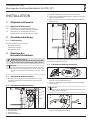
3.2 Klemmenleiste demontieren
D0000043724
1
4
2
3
1 Befestigungsschraube
2 Klemmenleiste
3 Gebläsemotor
4 Kabeldurchführung
Die Kabeldurchführung ist durch die Litzen verdeckt.
Legen Sie die Kabeldurchführung frei, indem Sie die Klem-
menleiste demontieren:
Lösen und entnehmen Sie die Befestigungsschraube der
Klemmenleiste.
D0000043725
Klappen Sie die gelöste Klemmenleiste nach unten.
Die Kabeldurchführung liegt frei.
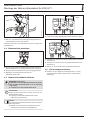
3.3 Kabelverschraubung montieren
D0000043726
Drücken Sie die Kabelverschraubung von der Gerätein-
nenseite in die Kabeldurchführung.
Lassen Sie die Kabelverschraubung in die Kabeldurchfüh-
rung einrasten.
Hinweis
Die Länge des Netzanschlusskabels im Geräteinneren
muss 220mm betragen.
D0000043727
Führen Sie das Netzanschlusskabel von der Geräterücksei-
te durch die Kabelverschraubung.

KURZANLEITUNG
Montage des Netzanschlusskabels für HTE | HTT
2 | 314781-37971-8974
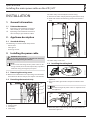
1.
2.
D0000043728
Ziehen Sie die Kontermutter (Linksgewinde) handfest an.
Ziehen Sie die Kabelverschraubung (Rechtsgewinde) an
der Hutmutter mit einer Zange fest.
Durch das Festziehen der Hutmutter zieht sich auch die Kon-
termutter fest.
3.4 Klemmenleiste montieren
D0000043729
Stecken Sie das Ende des Netzanschlusskabels zwischen
den Steckpunkten L und N der Klemmenleiste hindurch.
Bringen Sie die Klemmenleiste in ihre Ausgangsposition.
Befestigen Sie die Klemmenleiste mit der
Befestigungsschraube.
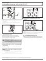
3.5 Netzanschlusskabel installieren
WARNUNG Stromschlag
Aufgeladene interne Kapazitäten können bei Berüh-
rung der Netzsteckerkontakte einen Stromschlag
verursachen.
Installieren Sie den Entladewiderstand.
!
Sachschaden
Achten Sie darauf, dass keine Litzen im Bereich des
Gebläsemotors liegen.
Verlegen Sie das Netzanschlusskabel rechts
neben der Klemmenleiste.
Hinweis
Das Netzanschlusskabel mit Stecker ist für eine Steck-
dose vorgesehen.
Achten Sie darauf, dass die Steckdose nach der
Installation des Gerätes frei zugänglich ist.
D0000043730
1
1 Entladewiderstand
Installieren Sie den Entladewiderstand zwischen L und N.
D0000043731
Schließen Sie die braune Litze an den Kontakt L der Klem-
menleiste an.
Schließen Sie die blaue Litze an den Kontakt N der Klem-
menleiste an.
Ziehen Sie die Schrauben der Klemmenkontakte fest.
3.6 Gehäusekappe montieren
Beachten Sie die Angaben in der Bedienungs- und Ins-
tallationsanleitung des Händetrockners (siehe Kapitel
„Montage“).

QUICK GUIDE
Installing the mains power cable on the HTE | HTT
314781-37971-8974 | 3
INSTALLATION
1. General information
1.1 Relevant documents
Operating and installation instructions
HTE hand dryer, part number 165505
Operating and installation instructions
HTT hand dryer, part number 171465
2. Appliance description
2.1 Standard delivery
The following are delivered with the product:
- Power cable
- Cable gland
- Discharge resistor
3. Installing the power cable
WARNING Electrocution
Ensure that the appliance is isolated from the mains
power supply during installation.
Note
In the event of damage to the power cable or dis-
charge resistor, these must be replaced by a qualied
contractor using our original spare parts.
3.1 Removing the casing cover
Observe the information in the operating and installation
instructions for the hand dryer (see chapter "Installation").
3.2 Detaching the terminal strip
D0000043724
1
4
2
3
1 Fixing screw
2 Terminal strip
3 Fan motor
4 Cable entry
The cable entry is covered by the internal wiring.
Uncover the cable entry by detaching the terminal strip:
Undo and remove the mounting screw on the terminal
strip.
D0000043725
Pivot the detached terminal strip downward.
The cable entry is now clear.
3.3 Installing the cable gland
D0000043726
Push the cable gland into the cable entry from inside the
appliance.
Ensure the cable gland clicks into place inside the cable
entry.
Note
A 220mm length of power cable is required inside
the appliance.
D0000043727
Route the power cable through the cable gland from the
back of the appliance.

QUICK GUIDE
Installing the mains power cable on the HTE | HTT
4 | 314781-37971-8974
1.
2.
D0000043728
Tighten the lock nut (left-hand thread) hand-tight.
Tighten the cable gland (right-hand thread) by the cap nut
using pliers.
As you tighten the cap nut, the lock nut will also tighten.
3.4 Fitting the terminal strip
D0000043729
Pass the end of the power cable between the L and N ter-
minals of the terminal strip.
Return the terminal strip to its original position.
Secure the terminal strip with the mounting screw.
3.5 Installing the power cable
WARNING Electrocution
Charge-bearing internal capacitances can cause
electrocution if the mains plug contacts are touched.
Install the discharge resistor.
!
Material losses
Ensure that there are no wires in the vicinity of the
fan motor.
Route the power cable along the right, by the ter-
minal strip.
Note
The mains power cable is supplied with a plug for a
standard socket.
Ensure that the socket is easily accessible once the
appliance has been installed.
D0000043730
1
1 Discharge resistor
Install the discharge resistor between the L and N
contacts.
D0000043731
Attach the brown wire to the L contact on the terminal
strip.
Attach the blue wire to the N contact on the terminal strip.
Tighten the screws on the terminal contacts.
3.6 Assembling the casing cover
Observe the information in the operating and installation
instructions for the hand dryer (see chapter "Installation").
STIEBEL ELTRON GmbH & Co. KG | Dr.-Stiebel-Str. 33 | 37603 Holzminden | [email protected]
-
 1
1
-
 2
2
-
 3
3
-
 4
4


STIEBEL ELTRON Netzanschlusskabel HTE HTT Operation Instruction
- Typ
- Operation Instruction
- Dieses Handbuch eignet sich auch für
in anderen Sprachen
Verwandte Artikel
-
STIEBEL ELTRON Netzanschlusskabel Ultronic Operation Instruction
-
-
-
-
-
-