
1
BEDIENUNGSANLEITUNG
USER´s MANUAL
MIC-AMP F366
AVAILABLE MODELS
MIC-AMP F366-S(ingle): 2-ch Microphone Preamplifier
MIC-AMP F366-D(ual): 4-ch Microphone Preamplifier
MIC-AMP F366-T(riple): 6-ch Microphone Preamplifier
Inhalt / Content Seite / Page
Allgemeine Sicherheitshinweise 2
Anschluss / Steckerbelegung 3
Bedienungsanleitung 4
General Safety Instructions 7
Connection / Connectors 8
User´s Manual 9
Technische Daten / Technical Specifications 12
Jumper Settings 13
Konformitätserklärung / Conformity Statement 14
development and
manufacturing of
audio electronic
Turmstrasse 7a
78467 Konstanz
GERMANY
Tel. +49 (0) 7531 73678
Fax +49 (0) 7531 74998
www.lake-people.de

2
Allgemeine Sicherheitshinweise
WARNUNG
Bitte lesen Sie die folgenden Sicherheitshinweise:
Wasser, Flüssigkeiten, Feuchtigkeit:
Das Gerät soll nicht in der Nähe von Wasser- oder Flüssigkeitsquellen benutzt werden.
Das Gerät soll nicht in Bereichen grosser Feuchtigkeit betrieben werden.
Achten Sie darauf, dass das Gerät nicht in Flüssigkeiten fällt, oder dass Flüssigkeiten durch die
Gehäuseöffnungen eindringen können.
Externe Stromversorgung:
Das Gerät sollte nur mit der mitgelieferten Stromversorgung betrieben werden.
Andere Stromversorgungen können unter der Voraussetzung verwendet werden, das eine stabile
Gleich- oder Wechselspannung im Bereich von 8 ... 35 Volt abgegeben wird.
Eine fremde externe Stromversorgung sollte mindestens das 1.5 fache des Stromes liefern können,
der auf der Rückseite des Gerätes vermerkt ist.
Spannungen über 35 Volt können zu Schäden führen die nicht durch die Garantie abgedeckt sind.
Das Gerät ist gegen Verpolungen der externen Betriebsspannung geschützt.
Die externe Stromversorgung erfolgt über einen 2-poligen 3.5 mm Klinkenstecker mit folgender
Belegung:
+ U
- U (Ground)
Service / Reparatur:
Um das Risiko von Feuer und Stromschlag zu reduzieren, soll dieses Gerät vom Benutzer nicht über
die in dieser Bedienungsanleitung beschriebenen Arbeiten hinaus gewartet oder repariert werden.
Überlassen Sie Service- und Reparaturarbeiten qualifiziertem Personal !!
Elektromagnetische Verträglichkeit:
Dieses Gerät entspricht internationalen Spezifikationen, die am Ende dieser Bedienungsanleitung in
der KONFORMITÄTSERKLÄRUNG beschrieben sind mit den folgenden Voraussetzungen:
- dieses Gerät strahlt keine störenden Emissionen aus
- dieses Gerät kann in störenden Umgebungen betrieben werden, auch wenn diese den
beabsichtigten Einsatzzweck des Gerätes beeinträchtigen
- der Betrieb dieses Gerätes in Umgebungen mit hohen elektromagnetischen Feldern sollte
vermieden werden
VOR DEM ÖFFNEN NETZSTECKER
ZIEHEN!! PULL MAINS BEFORE
OPENING!! AVANT D´OUVRIER
RETIREZ LA FICHE MALE!!

3
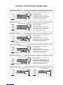
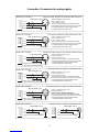
Anschluss / Steckerbelegung für analoge Signale
SOURCE
12
3
HOT
COLD
SHIELD
X
Symmetrisches Kabel (Signal) an (Trafo)symmetrischen Eingang
BALANCED INCOMING SIGNAL
XLR MALE PLUG
Shield / Abschirmung = Signalmasse = Pin 1
Hot / + Phase = Pin 2
Cold / - Phase = Pin 3
Das Steckergehäuse sollte nicht mit der
Abschirmung des Kabels verbunden werden.
Es wird beim Anschluss an das Gerät auf
das Gehäusepotential (PE) gelegt !
ANALOGE SIGNALE
DESTI-
NATION
12
3
HOT
COLD
SHIELD
X
(Trafo)symmetrischer Ausgang an symmetrisches Kabel
BALANCED OUTGOING SIGNAL
XLR FEMALE PLUG
Shield / Abschirmung = Signalmasse = Pin 1
Hot / + Phase = Pin 2
Cold / - Phase = Pin 3
Das Steckergehäuse sollte nicht mit der
Abschirmung des Kabels verbunden werden.
Es wird beim Anschluss an das Gerät auf
das Gehäusepotential (PE) gelegt !
ANALOGE SIGNALE
SOURCE
12
3
HOT
GND
SHIELD
X
Unsymmetrisches Kabel (Signal) an (Trafo)symmetrischen Eingang
BALANCED INCOMING SIGNAL
XLR MALE PLUG
Shield / Abschirmung = Signalmasse = Pin 1
Hot / Signal = Pin 2
Cold / Ground = Pin 3
Das Steckergehäuse sollte nicht mit der
Abschirmung des Kabels verbunden werden.
Es wird beim Anschluss an das Gerät auf
das Gehäusepotential (PE) gelegt !
ANALOGE SIGNALE
DESTI-
NATION
12
3
HOT
GND
SHIELD
X
Trafosymmetrischer Ausgang an unsymmetrisches Kabel
BALANCED OUTGOING SIGNAL
XLR FEMALE PLUG
Shield / Abschirmung = Signalmasse = Pin 1
Hot / Signal = Pin 2
Cold / Ground = Pin 3
Das Steckergehäuse sollte nicht mit der
Abschirmung des Kabels verbunden werden.
Es wird beim Anschluss an das Gerät auf
das Gehäusepotential (PE) gelegt !
ANALOGE SIGNALE
?
?
2-adrige Kabel sind zu bevorzugen !!
2-adrige Kabel sind zu bevorzugen !!
SOURCE
HOT HOT
GND GND
SHIELD SHIELD
Unysmmetrischer Eingang / Ausgang an unsymmetrisches Kabel
UNBALANCED INCOMING SIGNAL UNBALANCED OUTGOING SIGNAL
CINCH/BNC PLUG CINCH/BNC PLUG
ANALOGE SIGNALE
DESTI-
NATION
DESTI-
NATION
12
3
HOT
GND
SHIELD
X
Elektronisch symmetrischer Ausgang an unsymmetrisches Kabel
BALANCED OUTGOING SIGNAL
XLR FEMALE PLUG
Shield / Abschirmung = Signalmasse = Pin 1
Hot / Signal = Pin 2
(
Das Steckergehäuse sollte nicht mit der
Abschirmung des Kabels verbunden werden.
Es wird beim Anschluss an das Gerät auf
das Gehäusepotential (PE) gelegt !
Cold) = Pin 3 = unbedingt offen lassen !!
ANALOGE SIGNALE
2-adrige Kabel sind zu bevorzugen !!

4
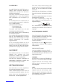
ALLGEMEINES
Der LAKE PEOPLE MIC-AMP F366 ist ein ex-
zellenter, extrem rauscharmer Mikrofon-Vor-
verstärker. Er ist als zwei-, vier- oder sechs-
kanaliges Gerät lieferbar.
Durch seine universelle Auslegung und hohe
Pegelfestigkeit ist er auch zum Verstärken
oder Symmetrieren von Line-Signalen ge-
eignet.
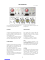
Die Verstärkung lässt sich in jedem Kanal mit
einen 12-stufigen Drehschalter in 6 dB Stufen
von 0...+66 dB einstellen.
Jeder Kanal ist mit Schaltern für
- Phase-Reverse und
- Low-Cut ausgestattet.
Für jeweils zwei Kanäle kann eine 48V
Phantomspeisung aktiviert werden.
Alle Schalter besitzen LEDs zur Rückmeldung
des aktivierten Zustands.
Eine 4-stufige LED-Kette zeigt den Ausgangs-
pegel an. Die Empfindlichkeit der Anzeige
kann über einen internen Regler an die per-
sönlichen Anforderungen des Anwenders
angepasst werden.
Die Ein- und Ausgänge befinden sich auf der
Rückseite und sind elektronisch symmetrisch.
Optional kann der MIC-AMP F366 mit trafo-
symmetrischen Ausgängen versehen werden.
DAS GEHÄUSE
Das Gehäuse besteht aus 1 - 2 mm starkem
Edelstahl. Dies garantiert eine hohe
mechanische Stabilität und Widerstands-
fähigkeit gegen rauhe Umwelteinflüsse.
Durch die hohe elektrische Leitfähigkeit der
unbehandelten Oberflächen ergeben sich
hervorragenden EMV Eigenschaften.
DIE STROMVERSORGUNG
Das Gerät sollte nur mit der mitgelieferten
Stromversorgung betrieben werden.
Andere Stromversorgungen können unter der
Voraussetzung verwendet werden, das eine
stabile Gleich- oder Wechselspannung im
Bereich von 8 ... 35 Volt abgegeben wird.
Eine fremde externe Stromversorgung sollte
mindestens das 1.5 fache des Stromes liefern
können, der auf der Rückseite des Gerätes
vermerkt ist.
Spannungen über 35 Volt können zu Schäden
führen die nicht durch die Garantie abgedeckt
sind.
Das Gerät ist gegen Verpolungen der externen
Betriebsspannung geschützt.
Die externe Stromversorgung erfolgt über
einen 2-poligen 3.5 mm Klinkenstecker mit
folgender Belegung:
+ U
- U (Ground)
Das Vorhandensein der Betriebsspannung
wird über grüne "POWER" LEDs auf der Front
angezeigt.
DAS ERDE/MASSE KONZEPT
Dieses Gerät wird mit einem externen Strom-
versorgung betrieben und besitzt daher keine
Zwangserdung durch das Netzkabel.
Der interne Bezugspunkt (Masse) ist mit dem
Gehäuse verbunden !!
Bei Bedarf kann an der mit bezeichneten
Stelle auf der Rückseite eine Erdleitung
befestigt werden.
XLR GROUD-LIFT Jumper
(von innen zugänglich, siehe auch Seite 15)
Um Brummstörungen zu begegnen, kann die
Masse/Erde-Beziehung der XLR Buchsen wie
folgt verändert werden.
G(ROUND):
Ab Werk sind alle Jumper auf G(ROUND) ge-
setzt. Pin 1 ist mit dem internen Masse-Be-
zugspunkt verbunden. HF Störungen werden
über einen 100 nF Kondensator auf das Ge-
häuse abgeleitet.
L(IFT):
Pin 1 ist nicht mit dem internen Masse-Be-
zugspunkt verbunden. HF Störungen werden
über einen 100 nF Kondensator auf das Ge-
häuse abgeleitet. Diese Stellung ist meist nur
mit Transformatoren sinnvoll !!

5
C(ASE):
Pin 1 ist mit dem Gehäuse verbunden, der 100
nF Kondensator ist überbrückt.
Sollte von den Werkseinstellungen
abgewichen werden, können
EMV Probleme entstehen.
Diese liegen im
Verantwortungsbereich des Nutzers !!
THEORIE UND PRAXIS
ZUR VERSTÄRKERSTUFE
Die Verstärkung im MIC-AMP F366 erfolgt
durch einen so genannten Instrumenten Ver-
stärker. Es ist ein für diese Zwecke optimier-
tes IC, dass sich durch seine Rauscharmut bei
hohen Verstärkungen und seine hohe Breit-
bandverstärkung auszeichnet.
Bei einer gewählten Verstärkung von +60 dB
(1000-fach) ergibt sich ein Rauschen, dass
lediglich ca. 2 dB über dem theroretisch erziel-
baren Minimum liegt.
Die Breitbandverstärkung (GBW = Gain Band-
width Product) und die Slew-Rate sind ursäch-
lich für den Klang eines Verstärkers verant-
wortlich.
Je höher sie ausfallen, desto transparenter ist
der Klang.
Die Slew-Rate des verwendeten Verstärkers
ist 10 V/us, das GBW errechnet sich aus dem
erzielten Frequenzgang bei einer bestimmten
Verstärkung.
Der MIC-AMP F366 hat bei einer Verstärkung
von +60 dB einen internen linearen Frequenz-
gang von weit über 200 kHz. Daraus ergibt
sich ein theoretisches GBW von 200 Mhz
(200.000 Hz * 1000).
DIE EINGÄNGE
Die elektronisch symmetrischen Eingänge
befinden sich auf der Rückseite des Gehäuses
und sind mit XLR Buchsen ausgestattet. Sie
sind mit "MIC IN 1/2 (3/4, 5/6)" bezeichnet. Die
Eingänge akzeptieren symmetrische und un-
symmetrische Audiosignale. Die Belegung ist
den internationalen Normen entsprechend
- 1 = Masse,
- 2 = (+) Phase,
- 3 = (-) Phase.
Bei unsymmetrischem Abschluss eines Ein-
gangs sollte Pin 3 auf Masse gelegt werden.
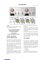
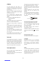
DIE BEDIENUNG (1, 2 oder 3 Module)

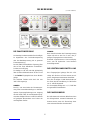
6
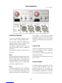
DIE PHANTOMSPEISUNG
Hochwertige Kondensatormikrofone benötigen
im allgemeinen eine Polarisationsspannung
oder eine Betriebsspannung, die so genannte
Phantomspannung.
Der MIC-AMP F366 stellt diese Spannung über
den auf der Front befindlichen "PHANTOM"-
Schalter zur Verfügung.
Sie beträgt ca. 48 Volt und wird gleichphasig
über 6,8 kOhm Widerstände auf die Pins 2 und
3 der beiden Eingangsbuchsen eines Moduls
gelegt.
Die aktivierte Funktion wird durch die rote
"48V"-LED angezeigt.
HINWEIS:
Das Ein- und Ausschalten der Phantomspan-
nung führt konstruktionsbedingt zu niederfre-
quenten Spannungsänderungen am Ausgang
des MIC-AMP F366, die nachfolgendes Equip-
ment beschädigen können. Achten Sie deshalb
auf geeignete Massnahmen zum Schutz der
nachfolgenden Geräte.
HINWEIS:
Nach dem Einschalten der Phantomspannung
stehen 48 Volt an den Pins 2 und 3 der je-
weiligen Eingangsbuchsen eines Moduls.
Eventuell angeschlossenes Line-Level-Equip-
ment - wie z.B. Synthesizer - kann hierdurch
beschädigt werden.
DIE VERSTÄRKUNGSEINSTELLUNG
Das Eingangssignal gelangt über die rück-
seitige XLR Buchse auf einen extrem rausch-
armen, integrierten Instrumenten-Verstärker.
Über den 12-stufigen "GAIN"-Drehschalter auf
der Front wird die Verstärkung in 6 dB Stufen
von 0...+66 dB eingestellt.
Die Genauigkeit beträgt min. +/- 0,3 dB über
den gesamten Einstellbereich.
DIE PHASENUMKEHR
Bei Aufnahmen mit mehreren Mikrofonen kann
der Klangeindruck eventuell bedeutend ver-
bessert werden, wenn die Phasenlage eines
oder mehrerer Mikrofone invertiert wird.
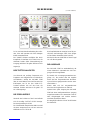
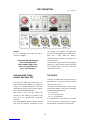
DIE BEDIENUNG (1, 2 oder 3 Module)

7
Sei es, weil die Mikrofonaufstellung dies erfor-
dert, oder weil irgendwo ein falsch belegtes
Kabel verwendet wurde.
Der "PHASE"-Schalter ermöglicht dies durch
Knopfdruck. Er befindet sich auf der Front, die
aktivierte Funktion (180o Phasendrehung am
Ausgang) wird durch die gelbe "REVerse"-LED
angezeigt.
DER TRITTSCHALLFILTER
Um störende und unnötige Frequenzen wie
Popplaute und Griffgeräusche an Mikrofonen
auszublenden, verfügt der MIC-AMP F366
über ein zuschaltbares Low-Cut Filter mit einer
Eckfrequenz von 70 Hz. Der "LOW-CUT"-
Schalter befindet sich auf der Front, die
aktivierte Funktion wird durch die gelbe "70
Hz"-LED angezeigt.
DIE PEGELANZEIGE
Oberhalb der Schalter auf der Front befindet
sich die 4-stufige "OUTPUT LEVEL"-Anzeige.
Der Anzeigeumfang ist 15 dB.
Die Charakteristik entspricht der DIN-Vorschrift
mit einer Ansprechzeit von <10 ms und einer
Abfallzeit von 1.5 s für 20 dB.
Die Empfindlichkeit der Anzeige ist auf die per-
sönlichen Anforderungen über einen Regler
auf der Platine einstellbar (siehe Seite 15).
Ab Werk ist die rote 0 dB LED auf einen Pegel
von +15 dBu eingestellt.
DIE AUSGÄNGE
Der MIC-AMP F366 ist standardmässig mit
einem elektronisch symmetrischen XLR Aus-
gang pro Kanal ausgestattet.
Es handelt sich um zwangssymmetrierte Aus-
gänge, d.h. die positive oder die negative
Phase darf bei unsymmetrischem Abschluss
nicht auf Masse gelegt werden sondern muss
offen bleiben !!
Weiter stellt sich bei unsymmetrischem
Abschluss ein Pegelverlust von 6 dB ein.
Optional kann jeder Ausgang des MIC-AMP
F366 mit einem trafosymmetrischen Ausgang
ausgerüstet werden. Der verwendete Trafo ist
aktiv rückgekoppelt und erreicht dadurch
exzellente dynamische Werte.
Die Ausgänge befinden sich auf der Rückseite
des Gehäuses.
DIE BEDIENUNG (1, 2 oder 3 Module)

8
General Safety Instructions
WARNING
For your protection, please read the following:
Water, Liquids, Moisture:
This appliance should not be used near water or other sources of liquids. Care should be taken so that
objects do not fall and liquids are not spilled into the enclosure through openings.
Power Sources:
The appliance should only be operated with the provided wallplug adaptor.
Other power sources may be used under the following circumstances:
The power source shall deliver a proper AC or DC voltage within the range of 8 … 12 Volt.
The power source shall be able to deliver 1.5 times the current which is marked on the back of the
unit.
Voltages exceeding 12 V may cause serious damages which are not covered by the warranty.
The unit is protected against reversed polarity.
The external power source is connected with a 3.5 mm phone-jack with the following assignment:
+ U
- U (Ground)
Service / Repair:
To reduce the risk of fire or electric shock, the user should not attempt to service the appliance beyond
that described in the operating manual. All other servicing or repair should be referred to qualified
personal !!
Electromagnetic Compatibility
This unit conforms to the Product Specifications noted as Declaration of Conformity at the end of
this manual. Operation is subject to the following conditions:
- this device may not cause harmful interferences
- this device must accept any interference received, including interference that may cause
undesired operation
- this device must not be operated within significant electromagnetic field
VOR DEM ÖFFNEN NETZSTECKER
ZIEHEN!! PULL MAINS BEFORE
OPENING!! AVANT D´OUVRIER
RETIREZ LA FICHE MALE!!

9
Connection / Connectors for analog signals
SOURCE
12
3
HOT
COLD
SHIELD
X
Balanced Cable (Signal) to (Transformer) Balanced Input
BALANCED INCOMING SIGNAL
XLR MALE PLUG
Shield = Signal Ground = Pin 1
Hot / + Phase = Pin 2
Cold / - Phase = Pin 3
The case of the connector should not be wired
to the shield of the cable. The connector is routed
to earth potential (PE) when plugged into the
corresponding socket of the case !
ANALOG SIGNALS
DESTI-
NATION
12
3
HOT
COLD
SHIELD
X
BALANCED OUTGOING SIGNAL
XLR FEMALE PLUG (Transformer) Balanced Output to Balanced Cable
Shield = Signal Ground = Pin 1
Hot / + Phase = Pin 2
Cold / - Phase = Pin 3
The case of the connector should not be wired
to the shield of the cable. The connector is routed
to earth potential (PE) when plugged into the
corresponding socket of the case !
ANALOG SIGNALS
SOURCE
12
3
HOT
GND
SHIELD
X
Unbalanced Cable (Signal) to (Transformer) Balanced Input
BALANCED INCOMING SIGNAL
XLR MALE PLUG
Shield = Signal Ground = Pin 1
Hot / Signal = Pin 2
Cold / Ground = Pin 3
The case of the connector should not be wired
to the shield of the cable. The connector is routed
to earth potential (PE) when plugged into the
corresponding socket of the case !
ANALOG SIGNALS
DESTI-
NATION
12
3
HOT
GND
SHIELD
X
BALANCED OUTGOING SIGNAL
XLR FEMALE PLUG Transformer Balanced Output to Unbalanced Cable
Shield = Signal Ground = Pin 1
Hot / Signal = Pin 2
Cold / Ground = Pin 3
The case of the connector should not be wired
to the shield of the cable. The connector is routed
to earth potential (PE) when plugged into the
corresponding socket of the case !
ANALOG SIGNALS
?
?
2-wire cable should be prefered !!
2-wire cable should be prefered !!
SOURCE
HOT HOT
GND GND
SHIELD SHIELD
Unbalanced Input / Output to Unbalanced Cable
UNBALANCED INCOMING SIGNAL UNBALANCED OUTGOING SIGNAL
CINCH/BNC PLUG CINCH/BNC PLUG
ANALOG SIGNALS
DESTI-
NATION
DESTI-
NATION
12
3
HOT
GND
SHIELD
X
BALANCED OUTGOING SIGNAL
XLR FEMALE PLUG Electronically Balanced Output to Unbalanced Cable
Shield = Signal Ground = Pin 1
Hot / Signal = Pin 2
The case of the connector should not be wired
to the shield of the cable. The connector is routed
to earth potential (PE) when plugged into the
corresponding socket of the case !
(Cold) = Pin 3 = must be left open !!
ANALOG SIGNALS
2-wire cable should be prefered !!

10
GENERAL
The LAKE PEOPLE MIC AMP F366 is an
excellent and extremely low-noise microphone
preamplifier. It is deliverable as a two, four or
six channel unit.
Due to its versatile concept and high level
capapility it is also suitable for line signal
boosting and balancing.
Gain is controlled with a twelve-step rotary
switch which sets gain in 6-dB steps from 0 to
+66 dB.
Each channel is equipped with switches for
- Phase Reverse and
- Low Cut.
48V Phantom supply may be activated for both
channels of a module simultaneously.
The state of all these switches is reported by
LEDs.
A four-segment LED bargraph displays the
output level over a range of 15 dB. Display
sensitivity can be adjusted internally to the
user's requirements.
The inputs and outputs are situated on the
back panel, they are equipped with gold plated
XLR connectors.
As an option, the MIC AMP F366 can be
equipped with transformer balanced outputs.
THE CASE
The grounded case is made of 1 - 2 mm thick
stainless steel. This provides high mechanical
stability and resistance against rough handling.
The cases surfaces are not treated with any
material, so providing excellent electrical con-
ductances for optimum EMC characteristics.
THE POWER SUPPLY
The unit should only be operated with the
provided wallplug adaptor.
Other power sources may be used under the
following circumstances:
The power source shall deliver a proper AC or
DC voltage within the range of 8 … 35 Volt.
The power source shall be able to deliver 1.5
times the current which is marked on the back
of the unit.
Voltages exceeding 35 V may cause serious
damages which are not covered by the
warranty.
The unit is protected against reversed polarity.
The external power source is connected with a
3.5 mm phone-jack with the following
assignment:
THE EARTH/GROUND CONCEPT
This unit is powered by an external source and
thus is not including a power cord with
ground/earth facilities.
The internal reference point (Ground) is
connected to the case !!
If desired, a earth or grounding wire may be
attached to the point marked on the back
panel.
XLR GROUD-LIFT Jumper
(accesible from the inside, see also page 15)
G(ROUND):
Ex works all jumpers are set to G(ROUND)
position. Pin 1 is connected to the internal
ground reference. High frequency interferen-
ces are deflected to the case via a 100 nF
capacitor.
L(IFT):
The interconnection between Pin 1 and ground
is open. High frequency interferences are
deflected to the case via a 100 nF capacitor.
This jumper position is useful when the unit is
equipped with transformers !!
+ U
- U (Ground)

11
C(ASE):
Pin 1 is connected to the case, the 100 nF
capacitor is bridged.
Please note that with jumpers in
LIFT or GROUND position
EMC problems might occure.
Theses are in the field of the
user´s responsibility !!!!
THE AMPLIFIER STAGE:
THEORY AND PRACTICE
The MIC AMP F366's gain is effected by a so
called instrumentation amplifier. It is represen-
ted by an IC specially designed for this task,
distinguishing itself by very low noise figures
and a high gain/bandwidth product.
When gain is set to +60 dB (x1000), the
amount of noise added is only approx. 2 dB
more than the (theoretically) achievable
minimum.
The gain/bandwidth product (GBW) and the
slew rate are basically responsible for the
sonic quality of an amplifier. The higher they
are, the more transparent the sound becomes.
Slew rate is 10V/s, while the GBW is
calculated from the frequency response at a
certain gain ratio.
The MIC AMP F366's internal linear frequency
response at +60 dB gain exceeds 200 kHz.
The resulting GBW is as high as 200 MHz
(200.000 Hz x 1000).
THE INPUTS
The back mounted balanced inputs appear as
gold plated XLR connectors. They are marked
“MIC IN 1/2 (3/4, 5/6)“.
The inputs accept balanced as well as unba-
lanced audio signals. XLR wiring corresponds
to international standard with
- Pin 1 = ground,
- Pin 2 = + (in phase) and
- Pin 3 = - (out of phase).
If an unbalanced source must be connected,
one of the phases (preferably the negative
one) should be connected to signal ground.
THE OPERATION THE OPERATION (1, 2 or 3 Moduls)

12
PHANTOM POWERING
The use of professional condenser micro-
phones requires so-called phantom powering.
The MIC AMP F366 offers stabilized 48V
phantom powering, which is activated by the
"PHANTOM"-button on the front panel.
This voltage is applied to pins 2 and 3 via
matched 6.8 kOhms resistors of both input
connectors.
Active phantom powering is indicated by a red
"48V"-LED.
NOTE:
Switching the phantom power during operation
produces low-frequency voltage swing at the
MIC AMP F366's output. To avoid damage of
monitor loudspeakers or other equipment, the
subsequent input should be muted when
pressing the "PHANTOM"-switch.
NOTE:
If unbalanced equipment such as synthesizers
etc. are connected to the MIC AMP F366's
inputs, the 48V phantom voltage might cause
damage if the connection is not made properly.
This problem is faced with all phantom
powered inputs and can be avoided by using a
transformer coupled D.I. box or by strictly
keeping the unbalanced wiring apart from pin 1
(ground).
GAIN SETTING
The input signal applied to the XLR terminal is
fed to an extremely low-noise integrated
instrumentation amplifier.
Gain is set by the "GAIN"-rotary switch in 6dB
steps from 0 to +66 dB.
The deviation from the indicated value is less
than +/- 0.3 dB.
PHASE REVERSE
In multiple microphone applications, inverting
one or several microphones' phase can
significantly improve the the overall mix.
Reason therefore may be position-dependent
time lags between microphones or, in the worst
case, an incorrectly soldered microphone lead.
THE OPERATION (1, 2 or 3 Moduls)

13
The "PHASE"-switch inverts signal polarity and
is confirmed by the yellow "REV"- LED.
LOW CUT
In order to reduce undesired frequencies such
as wind or microphone handling noise, the
MIC-AMP F366 offers a Low-Cut Filter with a
corner frequeny of 70 Hz.
It is switchable into the signal path by the
"LOW-CUT"-Switch situated on the frontpanel.
Activ state is displayed by the "70 Hz"- LED.
LEVEL METER
Situated on the front panel above the switches
already mentioned, a four-segment LED bar-
graph displays the momentary output level.
The overall display range is 15 dB.
The dynamic characteristics are according to
DIN specifications, with a rise time of <10
milliseconds and 1.5 seconds release time for
a 20 dB level change.
The display's sensitivity can be adjusted on the
main PCB to meet user-specific requirements
(see page 15 for details).
Ex works the red 0-dB LED is adjusted to +15
dB output level.
THE OUTPUTS
Each channel offers a balanced output with
gold plated XLR-type connectors. They are
situated on the rear of the unit and marked
"LINE OUT 1/2 (3/4, 5/6)".
The polarity meets AES 14-1992:
1 = Ground, 2 = (+) Phase, 3 = (-) Phase
The output impedance is approx. 30 ohms.
HINT:
In case of unbalanced termination of the
electronically balanced outputs, pin 3 of the
XLR connector may not be shortened but must
be left open! Signal level is reduced by 6 dB!
OPTION
As an option MIC-AMP F366 may be equipped
with high quality output transformers. These
transformers are controlled by a special cir-
cuitry to achieve low inner resistance, very
good frequency range and low distortions.
They exceed IRT recommendations.
THE OPERATION (1, 2 or 3 Moduls)
THE OPERATION (1, 2 or 3 Moduls)

14
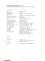
TECHNICAL DATA MIC-AMP F366 S / D / T
All measurement RMS unweighted, 20 Hz - 20 kHz, relativ to 0 dBu as not otherwise noted
Number of channels: 2 / 4 / 6
Input: electronically balanced
Input Impedance: 6,8 kOhm
Input CMRR (15 kHz): < 60 dB (A = 0 dB) / < 80 dB (A = +60 dB)
max. Input Level: > +21 dBu
Gain : 0...+66 dB in 12 Steps of 6 dB (Accuracy < 0.3 dB)
Phantom Voltage (switchable): 48 Volt ( +/- 5 %)
Phase Reverse (switchable): 180o phase rotation
Lowcut: 70 Hz (-3 dB), 12 dB/oct., 2-pol Filter
Internal Bandwidth (-3 dB): > 200 kHz (at +60 dB Gain)
Frequency Range (electr. bal.): 5 Hz....30 kHz (-0.5 dB)
Frequency Range (transf. bal.): 20 Hz...30 kHz (+/-0.5 dB)
THD+N (electr. bal.): < 0.002 % (G = 0 dB) / 0.03 % (G = +60 dB)
THD+N (transf. bal. 40 Hz...20 kHz): < 0.01 % (G = 0 dB) / 0.05 % (G = +60 dB)
Noise (Rin = 200 Ohm): < -98 dB (G = 0 dB) / -68 dB (G = +60 dB)
max. Ouput Level (bal.): > +21 dBu in RL > 600 Ohm
Output CMRR (15 kHz): < -60 dB (electr. bal.) / -60 dB (transf. bal.)
Level Display: 4 LED's, Range 15 dB, adjustable
Characteristic: according to DIN, attack <10ms, release 1.5 s (20 dB)
Relative level: adjustable from 0...+21 dBu for 0 dB LED
Internal supply voltages: Audio supply voltage +/- 15 Volt,
Phantom voltage +48 Volt, regulated, +/- 5 %
Meter reference +5 Volt, regulated +/- 2 %
General
Supply Voltage: AC or DC, 8 … 35 V,
4 VA (F366 S), 7 VA (F366 D), 10 VA (F366 T)
Dimensions: 483x44x166 mm (BxHxT)
OPTIONS: Each output may be equipped with a transformer.

15
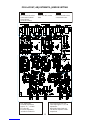
PCB LAYOUT, ADJUSTMENTS, JUMPER SETTING
C-L-G C-L-G C-L-G
Pin 1 from XLR socket
connected to internal
Ground-Plane.
(ex Works setting)
Pin 1 from XLR socket
lifted. Pin 1 from XLR socket
connected to case.
.
Left / Right Meter
sensitivity adjustment
Approx. +6 … +25 dBu
for 0 dBr LED
Ex Works adjusted to
+15 dBu for 0 dBr LED
Left / Right Gain Fine Trim
Total range approx. +/- 0,5 dB
Adjustment:
With 0 dBu input signal and
+18 dBGain adjust to +18 dB
output level.

16
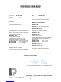
KONFORMITÄTSERKLÄRUNG
CONFORMITY STATEMENT
-----------------------------------------------------------------------------
Konstanz 26.09.2014, Fried Reim, Geschäftsführer / CEO
Wir bestätigen hiermit, dass das folgende Gerät:
Bezeichnung: MIC-AMP F366
Serien Nr. : -Alle-
mit folgenden EU-Richtlinien bzw. Normen
übereinstimmt:
93/68/EWG; Niederspannungsrichtlinie
A
ngewandte harmonisierte Norm:
EN 60065 : 2002
2001/95/EG, Produktsicherheitsrichtlinie
2014/30/EU, EMV Richtlinie
Zur Beurteilung des Erzeugnisses hinsichtlich seiner
elektromagnetischen Verträglichkeit wurden
folgende, harmonisierten Vorschriften angewendet:
EN 61000-6-3 : 2007
Fachgrundnorm Störaussendung
EN 61000-6-1 : 2007
Fachgrundnorm Störfestigkeit
Produktfamiliennorm für Audio- Video- und
audiovisuelle Einrichtungen sowie für Studio-
Lichtsteuereinrichtungen für professionellen Einsatz:
EN 55103-1 / 2005 Teil 1: Störaussendung
EN 55103-2 / 2005 Teil 2: Störfestigkeit
2011/65/EU, RoHS Richtlinie
2012/19/EU, WEEE Richtlinie
(Mitgliedsnummer: DE 26076388)
Für diese Erklärung ist der Hersteller verantwortlich:
We herewith declare that the following unit:
Name : MIC-AMP F366
Serial No: -all-
is in conformity with the following EC directives:
93/68/EEC; Low voltage directive
A
pplied harmonized Standard:
EN 60065 : 2002
2001/95/EC, general Product Safety Directive
2014/30 EC EMC directive
For verification of conformity with regard to
electromagnetic compability the following
harmonized standards are applied:
EN 61000-6-3 : 2007
Generic emission standard
EN 61000-6-1 : 2007
Generic immunity standard
Product family standard for audio, video, audio-visual
and entertainment lightning control apparatus for
professional use:
EN 55103-1 / 2005 Part 1: Emission
EN 55103-2 / 2005 Part 2: Immunity
2011/65/EU, RoHS directive
2012/19/EU, WEEE directive
Member No. : DE 26076388
This declaration is given under responsibility of:
Lake People electronic GmbH
Turmstrasse 7a, D-78467 Konstanz
development and
manufacturing of
audio electronic
Turmstrasse 7a
78467 Konstanz
GERMANY
Tel. +49 (0) 7531 73678
Fax +49 (0) 7531 74998
www.lake-people.de
-
 1
1
-
 2
2
-
 3
3
-
 4
4
-
 5
5
-
 6
6
-
 7
7
-
 8
8
-
 9
9
-
 10
10
-
 11
11
-
 12
12
-
 13
13
-
 14
14
-
 15
15
-
 16
16


