Bresser 7002531 Bedienungsanleitung
- Kategorie
- Wetterstationen
- Typ
- Bedienungsanleitung

Weather Station · Wetterstation ·
3-in-1 Anemometer Pro · Windmesser Pro
EN Instruction manual
DE Bedienungsanleitung

DE
Besuchen Sie unsere Website über den folgenden QR Code oder Weblink um weitere
Informationen zu diesem Produkt oder die verfügbaren Übersetzungen dieser Anleitung zu
finden.
EN
Visit our website via the following QR Code or web link to find further information on this
product or the available translations of these instructions.
FR
Si vous souhaitez obtenir plus d’informations concernant ce produit ou rechercher ce mode
d’emploi en d’autres langues, rendez-vous sur notre site Internet en utilisant le code QR ou le
lien correspondant.
NL
Bezoek onze internetpagina via de volgende QR-code of weblink, voor meer informatie over dit
product of de beschikbare vertalingen van deze gebruiksaanwijzing.
IT
Desidera ricevere informazioni esaustive su questo prodotto in una lingua specifica? Venga
a visitare il nostro sito Web al seguente link (codice QR Code) per conoscere le versioni
disponibili.
ES
¿Desearía recibir unas instrucciones de uso completas sobre este producto en un idioma
determinado? Entonces visite nuestra página web utilizando el siguiente enlace (código QR)
para ver las versiones disponibles.
CA
Voleu una guia detallada d'aquest producte en un idioma específic? Visiteu el nostre lloc web
a través del següent enllaç (codi QR) per accedir a les versions disponibles.
PT
Deseja um manual detalhado deste produto numa determinada língua? Visite a nossa Website
através da seguinte ligação (QR Code) das versões disponíveis.
www.bresser.de/P7002531
www.bresser.de/warranty_terms
GARANTIE · WARRANTY · GARANTÍA · GARANZIA
RECYCLAGE (TRIMAN/FRANCE)


4 / 52
1 Imprint
Bresser GmbH
Gutenbergstr. 2
46414 Rhede
Germany
www.bresser.de
For any warranty claims or service inquiries, please refer to
the information on "Warranty" and "Service" in this docu-
mentation. We ask for your understanding that unsolicited
returns cannot be processed.
Errors and technical changes excepted.
© 2023 Bresser GmbH
All rights reserved.
The reproduction of this documentation - even in extracts -
in any form (e.g. photocopy, print, etc.) as well as the use
and distribution by means of electronic systems (e.g. image
file, website, etc.) without the prior written permission of
the manufacturer is prohibited.
The designations and brand names of the respective com-
panies used in this documentation are generally protected
by trade, trademark and/or patent law in Germany, the
European Union and/or other countries.
2 Validity note
This documentation is valid for the products with the follow-
ing article numbers:
7002531 7902531
Manual version: 0623
Manual designation:
Manual_7002531-79002531_Wind-gauge-Windmesser_en-
de_BRESSER_v062023a
Always provide information when requesting service.

5 / 52
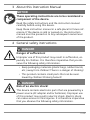
3 About this Instruction Manual
NOTICE
These operating instructions are to be considered a
component of the device.
Read the safety instructions and the instruction manual
carefully before using this device.
Keep these instruction manual in a safe place for future ref-
erence. If the device is sold or passed on, the instruction
manual must be passed on to any subsequent owner/user
of the product.
4 General safety instructions
DANGER
Danger of suffocation!
Improper use of this product may result in suffocation, es-
pecially for children. It is therefore imperative that you ob-
serve the following safety information.
• Keep packaging materials (plastic bags, rubber bands,
etc.) away from children! There is a danger of choking!
• This product contains small parts that can be swal-
lowed by children! Choking hazard!
DANGER
Risk of an electric shock!
This device contains electronic parts that are powered by a
power source (AC adapter and/or batteries). Improper use
of this product may result in electric shock. Electric shock
can cause serious or fatal injuries. It is therefore imperative
that you observe the following safety information.

6 / 52
• Never leave children unattended when handling the
device! Follow the instructions carefully and do not at-
tempt to power this device with anything other than
power sources recommended in this instruction
manual, otherwise there is a danger of an electric
shock!
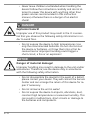
DANGER
Explosion hazard!
Improper use of this product may result in fire. It is essen-
tial that you observe the following safety information in or-
der to avoid fires.
• Do not expose the device to high temperatures. Use
only the recommended batteries. Do not short-circuit
the device or batteries, or throw them into a fire! Ex-
cessive heat or improper handling could trigger a
short-circuit, a fire or an explosion!
NOTICE
Danger of material damage!
Improper handling may result in damage to the unit and/or
accessories. Therefore, use the device only in accordance
with the following safety information.
• Do not disassemble the device! In the event of a defect,
please contact your dealer. They will contact the Service
Center and can arrange the return of this device for re-
pair if necessary.
• Do not immerse the unit in water!
• Do not expose the device to impacts, vibrations, dust,
constant high temperatures or excessive humidity. This
can result in malfunctions, short-circuits or damage to
the batteries and components.

7 / 52
• Use only the recommended batteries. Always replace
weak or empty batteries with a new, complete set of
batteries at full capacity. Do not use batteries from dif-
ferent brands or types or with different capacities. Re-
move batteries from the device if it is not to be used for
a longer period of time!
NOTICE
Risk of voltage damage!
The manufacturer is not liable for damage related to im-
properly installed batteries!
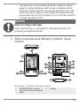
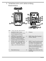
5 Parts overview and delivery content - base
station
1
2
7
9
8
10
11
12
19
3
4
5
6
15
18
17
16
14
13
20
21
A
B
Illustration1: All parts of the base station
1 SNOOZE/LIGHT button
(snooze function and back-
light)
2 Display

8 / 52
3 HISTORY button (show
hourly records for temper-
ature, humidity and wind
speed)
4 MEM button (show recor-
ded data)
5 INDEX button (display
change between 'feels like'
temperature, dew point,
heat index and wind chill in-
dex)
6 WIND button (wind speed
unit setting or display
change between hourly,
daily, monthly and yearly
top wind speed)
7 Wall mount 8 ALARM button (alarm time
setting)
9 CLOCK button (manual time
and date setting)
10 °C/°F slider (display change
betw. °C and °F)
11 AVG/GUST slider (display
change between average
wind speed (AVG) and gust
wind speed (GUST).
12 TUNE button (calibration of
base station and sensor)
13 ALERT button (set temperat-
ure and humidity alarm)
14 DOWN/Contrast button (de-
crease value setting or
change display contrast)
15 UP/CH button (increase
value setting or select
sensor channel)
16 RCC button (enable or dis-
able RCC signal)
17 SCAN button (initiate sensor
transmission)
18 RESET button (reset all set-
tings)
19 Battery compartment 20 Battery compartment cover
21 Stand, removable
Scope of delivery
Base unit (A), stand (B)
Recommended batteries (not included):2 pcs. of Mignon bat-
teries (1.5V AA type)

9 / 52
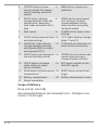
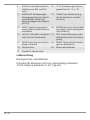
6 Parts overview and delivery content -
windmeter
2
3
4
10
1
12
11
3
6
7
5
4
9
13
C
12 17
15
14
16
11
4
8
Illustration2: All parts of the windmeter
1 Wind cups 2 Upper housing part
3 Bottom housing part 4 Thick fully threaded screw
5 LED Status indicator (flashes dur-
ing data transmission)
6 Radiation protection slats
7 Battery compartment 8 RESET button (reset all settings)
9 Battery compartment cover 10 Rod clamp on bottom housing
part
11 Thick nut 12 Mounting rod
13 Mounting base (for vertical and
horizontal assembly of the
mounting rod)
14 Thin nut
15 Thin partly threaded screw 16 Tube clamp (counterpart)
17 Rubber pads

10 / 52
Scope of delivery
Windmeter (C), 2x thin partly threaded screw with nut, 4x
thick fully threaded screw with nut and ring washer
Recommended batteries (not included):
3 pcs. of Mignon batteries (1.5V AA type) Mignon batteries
(1.5V, AA type)
7 Scope of delivery
Base unit (A), stand (B), windmeter (C), mounting material
incl. screws
Recommended batteries (not included)
Station: 2 pcs. Mignon batteries (1.5V, AA type)
Sensor: 3 pcs. Mignon batteries (1.5V, AA type)

11 / 52
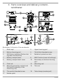
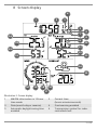
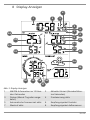
8 Screen display
123
5
4
6
7
10
8
9
11
12
13
14
15
19 16
20 18
17
21
22
23
24
Illustration3: Screen display
1 AM/PM information in 12-hour
time mode
2 Current time
(hours:minutes:seconds)
3 Date (month-day or reverse) 4 Frost warning enabled
5 Automatic daylight saving time
enabled
6 Transmission symbol for radio-
controlled clock

12 / 52
7 Alarm enabled 8 Reception symbol for outdoor
sensor
9 Outdoor temperature alarm en-
abled
10 Outdoor temperature
11 Sensor symbol 12 Outdoor humidity alarm enabled
13 Humidity outdoors 14 Weather forecast
15 Information on 'feels like' tem-
perature, wind chill, dew point
and heat index
16 Type of wind speed (Avg=aver-
age, Gust=current gust)
17 Wind speed 18 Top wind speed (hourly, daily,
monthly, yearly)
19 Wind speed alarm enabled 20 Wind speed classification (light,
moderate, strong, storm)
21 Indoor humidity 22 Indoor humidity alarm enabled
23 Indoor temperature 24 Indoor temperature alarm en-
abled
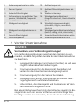
9 Before starting operation
NOTICE
Avoid connection faults!
In order to avoid connection problems between the devices,
the following points must be observed during commission-
ing.
1. Place the base unit (receiver) and sensor (transmitter)
as close together as possible.
2. Connect the power supply to the base unit and wait un-
til the indoor temperature is displayed.
3. Establish power supply for the sensor.
4. Set up/operate the base unit and sensor within the ef-
fective transmission range.
5. Make sure that the base unit and the radio sensor are
set to the same channel.

13 / 52
When changing the batteries, always remove the batteries
from both the base unit and the sensor and reinsert them in
the correct order so that the radio link can be re-estab-
lished. If one of the two devices is operated via a mains
power connection, the power connection must also be
briefly disconnected for this device when the batteries are
changed. If, for example, only the batteries in the sensor
are replaced, the signal may subsequently not be received
at all or not be received correctly.
Note that the actual range depends on the respective con-
struction materials used for the buildings as well as the re-
spective position of the base unit and the outdoor sensor.
External influences (various radio transmitters and other
sources of interference) can greatly reduce the possible
range. In such cases, we recommend finding other locations
for both the base unit and the outdoor sensor. Sometimes
moving the sensor by just a few centimeters is enough!
10 Setting up power supply
Base unit
1. Remove the battery compartment cover.
2. Insert the batteries into the battery compartment. En-
sure that the battery polarity (+/-) is correct.
3. Replace the battery compartment cover.
4. Wait until the indoor temperature is displayed on the
base station.
Windmeter
5. Unscrew the upper housing part from the bottom part.
6. Remove the battery compartment cover from the bot-
tom of the upper housing part.
7. Insert the batteries into the battery compartment. En-
sure that the battery polarity (+/-) is correct.
8. Replace the battery compartment cover.

14 / 52
9. Screw bottom housing part to upper housing part.
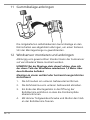
11 Attaching rubber linings
Attach the supplied self-adhesive rubber pads to the clamps
as shown to ensure a firmer fitting of the mounting rod.
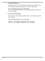
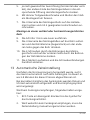
12 Windmeter installation and mounting
Depending on the desired location, the remote sensor can
be installed in different ways.
NOTICE!During the assembly make sure that the upper part
of the wind vane is minimum 1.5 metres off the ground.
Assembly on a vertical or horizontal wooden element
1. Remove the screws from the bottom housing part.
2. Pull off the rod clamp from the bottom housing part.
3. Insert one end of the mounting rod into the opening of
the rod clamp so that the position arrows match.
4. Fix the mounting rod to the rod clamp with a thin par-
tially threaded screw and a nut.
5. Depending on the desired orientation, slide the oppos-
ite end of the mounting od into the aperture for vertical
or horizontal mounting of the mounting base.

15 / 52
6. Fix the mounting rod to the mounting base with a thin
partially threaded screw and a nut.
7. Place the mounting base with its bottom site first on a
wooden element and fix it with 4 suitable wood screws.
Assembly on a vertical or horizontal tube
8. Repeat steps 1 to 6 as before.
9. Place the mounting base with its bottom site first on
the tube and press the tube clamp (counterpart)
against the tube from the opposite site.
10. Slide 4 screws through the bore holes of the mounting
base and through the bore holes of the tube clamp on
the other site.
11. Put on the 4 nuts and tighten the screw connection by
hand.
13 Automatic time setting
After the power supply was established, the clock will auto-
matically search for the radio signal. It takes about 3-8
minutes to complete this process.
If the radio signal is received correctly, the date and time
will be set automatically and the radio control signal icon
turns on.
If the clock fails to receive the time signal, go ahead with the
following steps:
1. Press RCC button on the base station until radio signal
symbol flashes.
2. If the device is still not receiving the signal, the time
must be set manually.

16 / 52
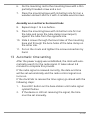
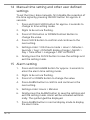
14 Manual time setting and other user defined
settings
To set the time / date manually, first disable the reception of
the time signal by pressing the RCC button for approx. 8
seconds.
1. Press and hold CLOCK button for approx. 3 seconds to
change to time setting mode.
2. Digits to be set are flashing.
3. Press UP/CH button or DOWN/Contrast Button to
change the value.
4. Press CLOCK button to confirm and continue to the
next setting.
5. Settings order: 12/24 hours mode > Hours > Minutes >
Seconds > Year > D/M-M/D display change > Month >
Day > Time offset > Language > DST AUTO/OFF
6. Finally press the CLOCK button to save the settings and
exit the setting mode.
15 Alarm setting
1. Press and hold ALARM button for approx. 3 seconds to
enter the alarm time setting mode.
2. Digits to be set are flashing.
3. Press UP or DOWN button to change the value.
4. Press ALARM button to confirm and continue to the
next setting.
5. Settings order: Hours > Minutes
6. Finally press the ALARM button to save the settings and
exit the setting mode. Alarm will be activated automat-
ically. The symbol will be displayed.
7. Press ALARM button in normal display mode to display
the alarm time.

17 / 52
8. Press ALARM button during the alarm time display to
disable the alarm.
16 Snooze function
1. When the alarm sounds press the SNOOZE/LIGHT but-
ton to activate the snooze function. The alarm will
sound again in 5 minutes.
2. Press ALARM button when the alarm sounds to inter-
rupt the alarm until the alarm time will be reached
again.
3. The alarm will be turned off automatically if no button
is pressed within 2 minutes.
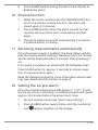
17 Receiving measurements automatically
Once the power supply is enabled, the base station will dis-
play the measurement readings. Readings from the remote
sensor will be displayed within 3 minutes after powering it
on.
If no signal is received, go ahead with the following steps:
Press SCAN button for approx. 2 seconds to initate recep-
tion of measurements again.
Read the detailed manual for more information about read-
ings (see download information on page 2).
18 Setting the ice pre-alarm
Once the outside temperature falls below 3 ° C (37 ° F) and
the ice pre-alarm is activated, an additional alarm will sound
approx. 30 minutes before the actual alarm time.
1. Set and activate alarm (see "Alarm time setting").
2. Press ALARM button several times until the symbols
and appear together on the display.

18 / 52
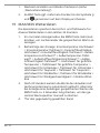
19 MAX/MIN Weather data
The base station stores the highest and lowest values for
various weather data over the last 24 hours:
1. In normal display mode, press MEM button several
times to display the saved values one after another.
2. Display order: Highest indoor temperature > Lowest in-
door temperature > Highest indoor humidity > Lowest
indoor humidity > Highest outdoor temperature* >
Lowest outdoor temperature* > Highest outdoor hu-
midity* > Lowest outdoor humidity* > Highest feels like
temperature > Lowest feels like temperature> Highest
value for heat index > Lowest value for heat index >
Highest value for dew point > Lowest value for dew
point > Highest value for wind chill> Lowest value for
wind chill> Maximum wind speed> Strongest gust
3. All values of the current recording period will automat-
ically be deleted after 24 hours. Optionally press the
MEM button for approx. 3 seconds to delete all stored
values manually.
4. *for the currently selected channel
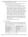
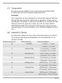
20 HI/LO Alert
HI/LO alert are used to alert you of certain weather condi-
tions. Once activated, an alarm sound is triggered and the
alert icon flashes as soon as a set value is reached. Suppor-
ted areas and alarm types:
Area Type of alert available
Indoor temperature HI AL / LO AL
Indoor humidity HI AL / LO AL
Outdoor temperature HI AL / LO AL
Outdoor humidity HI AL / LO AL
Rainfall (daily) HI AL*
Wind speed HI AL
HI AL = High alert / LO AL = Low alert

19 / 52
*Daily rainfall since midnight
HI/LO alert setting
1. Press ALERT button until the desired area is selected.
2. Press UP or DOWN button to change the value.
3. Press ALERT button to confirm and continue to the next
setting.
Enable/Disable HI/LO Alert
4. Press ALERT button until the desired area is selected.
5. Press ALARM button, to activate the alarm.
6. Press ALERT button to confirm and continue to the next
setting.
Note:
7. The unit will automatically exit setting mode in 5
seconds if no button is pressed.
8. When ALERT alarm is on, the area and type of alarm
that triggered the alarm will be flashing and the alarm
will sound for 2 minutes.
9. Press SNOOZE/LIGHT button when alarm sounds to in-
terrupt the alarm. The alarm will then start again after
2 minutes.
Data clearing
10. Press and hold HISTORY button for approx. 3 seconds.
11. Press UP or DOWN button to choose YES or NO.
12. Press HISTORY button to confirm. This will clear out any
rainfall data recorded before.

20 / 52
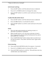
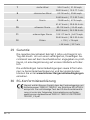
21 History data
The base station automatically records various wind meas-
urements.
Press the HISTORY button repeatedly to display the hourly
(HOURLY - up to 24 hours back), daily (DAILY - up to 31 days
back), monthly (MONTHLY - up to 12 months back) or yearly
(YEARLY - up to 3 years retroactively) maximum history data,
depending on the current display mode.
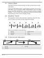
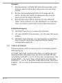
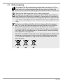
22 Weather Trend
The weather station will calculate a weather trend for the
next 12 hours on basis of the measured values.
123456
Illustration4: Weather trend indicators
1 Sunny 2 Partly cloudy
3 Cloudy 4 Rain
5 Storm 6 Snow
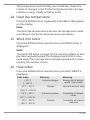
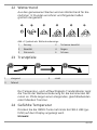
23 Trend arrow indicators
123
1 Rising 2 Steady
3 Falling
Seite wird geladen ...
Seite wird geladen ...
Seite wird geladen ...
Seite wird geladen ...
Seite wird geladen ...
Seite wird geladen ...
Seite wird geladen ...
Seite wird geladen ...
Seite wird geladen ...
Seite wird geladen ...
Seite wird geladen ...
Seite wird geladen ...
Seite wird geladen ...
Seite wird geladen ...
Seite wird geladen ...
Seite wird geladen ...
Seite wird geladen ...
Seite wird geladen ...
Seite wird geladen ...
Seite wird geladen ...
Seite wird geladen ...
Seite wird geladen ...
Seite wird geladen ...
Seite wird geladen ...
Seite wird geladen ...
Seite wird geladen ...
Seite wird geladen ...
Seite wird geladen ...
Seite wird geladen ...
Seite wird geladen ...
Seite wird geladen ...
Seite wird geladen ...
-
 1
1
-
 2
2
-
 3
3
-
 4
4
-
 5
5
-
 6
6
-
 7
7
-
 8
8
-
 9
9
-
 10
10
-
 11
11
-
 12
12
-
 13
13
-
 14
14
-
 15
15
-
 16
16
-
 17
17
-
 18
18
-
 19
19
-
 20
20
-
 21
21
-
 22
22
-
 23
23
-
 24
24
-
 25
25
-
 26
26
-
 27
27
-
 28
28
-
 29
29
-
 30
30
-
 31
31
-
 32
32
-
 33
33
-
 34
34
-
 35
35
-
 36
36
-
 37
37
-
 38
38
-
 39
39
-
 40
40
-
 41
41
-
 42
42
-
 43
43
-
 44
44
-
 45
45
-
 46
46
-
 47
47
-
 48
48
-
 49
49
-
 50
50
-
 51
51
-
 52
52


Bresser 7002531 Bedienungsanleitung
- Kategorie
- Wetterstationen
- Typ
- Bedienungsanleitung
in anderen Sprachen
- English: Bresser 7002531 Owner's manual
Verwandte Artikel
-
Bresser 7002531 Bedienungsanleitung
-
Bresser 3-in-1 Professional Wind Gauge / Anemometer Bedienungsanleitung
-
-
-
-
Bresser 7902580 Bedienungsanleitung
-
Bresser 9080500 - Colour Weather Center 5-in-1 National Geographic Bedienungsanleitung
-
-