
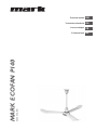
MARK ECOFAN P140
06 60 550_R01
Technical manual
Technisches Handbuch
Livret technique
Technisch boek
DE
EN
FR
NL

2

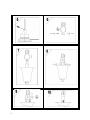
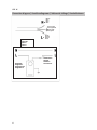
Producon label / Typenschild / Plaque signaléque / Type plaatje
FIG. I
GB DE FR NL
Mark BV
Name Name Nom Naam
Ecofan P140
Designaon Bezeichnung Désinaon Aanduiding
220V
Voltage Spannung Tension Voltage
50 Hz
Frequency Frequenz Fréquence Frequene
0.43 Amps
Amperage Stromstärke Intensité de courant Amperage
IP 55
Ingression
protecon
Schutzart Indice de protecon Beschermings-graad
CE
CE logo CE-Kennzeichnung Marquage CE CE-logo
cCSAus
CSA logo CSA Kennzeichnung Marquage CSA CSA logo
2011 - 1
Year of construcon Baujahr
L'année de
construcon
Bouwjaar
3

FIG. II
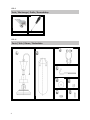
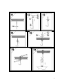
Tools / Werkzeuge / Ouls / Gereedschap
10mm
FIG. III
Parts / Teile / Pièces / Onderdelen
4

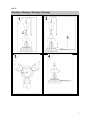
Assembly / Montage / Montage / Montage
FIG. IV
5

6

7

8

FIG. V
NL
Installatie instructies voor de installateur en gebruiker, betreffende veiligheid, installatie
en onderhoud van de plafondventilator PV600.
GB
Installation instructions for the installer and user regarding safety, installation and
maintenance of the ceiling fan PV600.
D
Installationsanleitung für den Installateur und Benutzer bezüglich Sicherheit, Installation
und Wartung des Deckenlüfters PV600.
F
Instructions d’installation pour I'installateur et l’utilisateur concernant la sécurité,
installation et I'entretien du ventilateur de plafond PV600.
≥ 2,70 meter
≥ 2,70 meter
9
NL
Installatie instructies voor de installateur en gebruiker, betreffende veiligheid, installatie
en onderhoud van de plafondventilator PV600.
GB
Installation instructions for the installer and user regarding safety, installation and
maintenance of the ceiling fan PV600.
D
Installationsanleitung für den Installateur und Benutzer bezüglich Sicherheit, Installation
und Wartung des Deckenlüfters PV600.
F
Instructions d’installation pour I'installateur et l’utilisateur concernant la sécurité,
installation et I'entretien du ventilateur de plafond PV600.
≥ 2,70 meter
≥ 2,70 meter
Ecofan P140
Ecofan P140
Ecofan P140
Ecofan P140

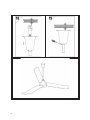
Connecon diagram / Anschlussdiagramm / Schéma de câblage / Aansluitschema
FIG. VI
Schakelaa r
Switch
Schalter
Contacteu r
Regelaar
Regulator
Regelgeräte
Régulateur
Bla uw
Bleu
Blau
Blue
Groen/geel
Green/yellow
Grun/gelb
Vert/jaun
Bruin
Brown
Braun
Brun
Optioneel
Optional
Option
Option
10

11

12
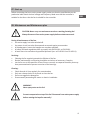
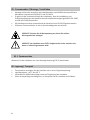
Warning
Incorrect installaon, adjustment, alteraon, repair or maintenance work may lead
to material damage or injury. All work must be carried out by cered, qualied
professionals. If the appliance is not posioned in accordance with the instrucons,
the warranty shall be rendered void. This appliance is not intended for use by children
or persons with a physical, sensory or mental handicap, or who lack the required
experience or experse, unless they are supervised or have been instructed in the use
of the appliance by somebody who is responsible for their safety. Children must be
supervised to ensure that they do not play with the appliance.
01. General
All rights reserved
The manufacturer has a policy of connuous product improvement and reserves the right to
make changes to the specicaons without prior noce. The technical details are considered
correct but do not form the basis for a contract or warranty. All orders are accepted subject
to the standard terms and condions of sale and delivery (which will be sent to you at your
request).
General warnings
Installaon must comply with the relevant local and/or naonal regulaons. You must
therefore have the Ecofan P140 installed by a professionally qualied installer in accordance
with all applicable naonal and internaonal regulaons. Faulty installaon, adjustment,
alteraon, maintenance acvity or repair shall render the warranty void.
READ THIS DOCUMENT BEFORE INSTALLING THE APPLIANCE

CAUTION: Do not install a damaged or incomplete fan.
This fan is made for moving or recirculang air. Using this fan in explosive environments for
moving or circulang gas, substances, sprays, fumes or a mixture thereof is not permied.
Moving or recirculaon of uids, solids or parculate maer is also not permied.
03. Scope of delivery
02. Introducon
Aer removing the packaging, check for completeness and integrity of the product.
Contact the supplier immediately in case of missing or damaged components.
Check the producon label for technical specicaons. Check voltage and frequency before
use.
Sound pressure measured towards the human ear in dB(A) according to “free eld method” at
a distance of 7 meters: 44 dB (A)
04. Technical Specicaons
To reduce the risk of re or electric schock, this fan should be used with an
approved fan speed controller.
To reduce the risk of personal injury, do not bend the blade brackets when
installing the brackets, balancing the blades or cleaning the fan. Do not insert
foreign objects in between the rotang fan blades.
The delivery contains:
Fan for mounng to ceiling:
•1 fan, unassembled
•1 hook
•1 yoke
•User manual
Opons:
•Motor protecon switch
13
EN

14
05. Assemby / mounng / installaon
• Mounng, electric connecon and start-up may be executed by qualied personnel only
(according to EN 50110-1 and EN 1010-1).
• It is the installer’s responsibility that the installaon and safety instrucons are in
accordance with current standards and regulaons (according to EN-ISO 13857 and EN
ISO 12100)
• Every fan has to be grounded according to the current standard EN 50178.
• Connect the fan according to the connecon diagram.
Switch o the mains supply before installing the fan.
CAUTION: The fan must ALWAYS be mounted in a stable way before being
taken into operaon!
05.1. Assembly
Assemble the fan according to the instrucons, see FIG IV in the assemby manual.
06. Storage / Transport
• Transport and store the fan only in its original packaging.
• Storage temperature: –40˚C to +60˚C.
• Avoid impacts and unnecessary loads to packaging and/or fan.
• In case the packaging is damaged, check for damages on the fan.

08. Maintenance and Maintenance plan
CAUTION: Never carry out mainenance work on a working/rotang fan!
Always disconnect from mains power supply before maintenance work.
During all maintenance of the fan:
• the mains supply has to be switched o.
• the power circuit has to be disconnected an secured against reconnecon.
• all rotang parts have to be brought to a complete standsll
• all safety and work regulaons have to comply with EN 50110-1 en EN 1010-1.
• all work has to be carried out by qualied personell (acc. to EN 50110-1 en EN 1010-1).
Servicing:
• Cleaning the fan regurlarly extends the lifeme of the fan.
• Roune maintenance and cleaning should be carried out at least every 6 months.
• Let the fan run at full speed for at least 2 hours a month, to evaporate humidity that may
have penetrated and to prevent corrosion of the bearings.
Cleaning:
• Check fan and air lines regularly for contaminaon.
• Only use a damp cloth or a dry brush to clean the fan.
• Do not use aggressive detergents
• Prevent water penetrang the motor or electric installaon.
WARNING!
Never spray water on the fan!
Prevent unexpected start-up of the fan! Disconnect from mains power supply
before rotang the impeller manually!
15
07. Start-up
Before connecng the fan to mains power supply, make sure that the specicaons on the
producon label match the local voltage and frequency. Make sure that the controller is
suitable for the fan or that the fan is suitable for the controller.
EN

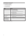
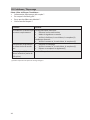
Fault Soluon
Fan does not start or rotates
too slow.
No power supply:
• Turn on mains power supply
• Switch on controller
• Check fuse and replace, if necessary(1)
With power supply:
• Check motor and replace, if necessary(1)
Motor protecon switch
turns the fan o.
• Clean
• Check motor and replace, if necessary (1)
• Repair or replace controller (1)
Impeller rotates slowly (less
than 330 rpm at full power
supply)
• Check if the correct voltage is supplied
(1) Use original spare parts only!
16
09. Malfuncons / Repairs
To be checked by the installer:
• Is there a problem with the mains power supply?
• Is the fuse blown?
• Is the wiring loose?
• Is the impeller blocked?

17
EN

18
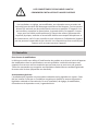
Warnhinweis
Fehlerha durchgeführte Installaonen, Einstellungen, Änderungen, Reparaturen oder
Wartungsmaßnahmen können zu Sachschäden und Verletzungen führen. Alle Arbeiten
müssen von geprüen, qualizierten Fachleuten durchgeführt werden. Falls das Gerät
nicht vorschrisgemäß aufgestellt wird, erlischt die Garane. Dieses Gerät ist nicht für
den Gebrauch durch Personen (einschließlich Kindern) mit verminderter körperlicher,
Sinnes- oder geisger Leistungsfähigkeit oder mangelnder Erfahrung und mangelnden
Kenntnissen besmmt, sofern sie nicht unter Aufsicht stehen oder durch eine Person,
die für ihre Sicherheit verantwortlich ist, im Gebrauch des Geräts angeleitet werden.
Kinder müssen vom Gerät ferngehalten werden.
01. Allgemeines
Änderungen vorbehalten
Der Hersteller strebt eine konnuierliche Verbesserung der Produkte an und behält sich das
Recht vor, ohne vorherige Mieilung Änderungen an den technischen Daten vorzunehmen.
Die technischen Angaben werden als korrekt angenommen, bilden aber keine Grundlage
für einen Vertrag oder Gewährleistungsansprüche. Alle Bestellungen werden gemäß den
Standardkondionen in unseren allgemeinen Verkaufs- und Lieferbedingungen angenommen
(diese werden auf Anfrage zur Verfügung gestellt).
Allgemeine Warnhinweise
Die Installaon muss den geltenden landesweiten und örtlichen Besmmungen entsprechen.
Daher darf das Gerät nur von einem sachkundigen und qualizierten Installateur unter
Beachtung der naonalen und internaonalen Vorschrien installiert werden. Im Falle einer
unsachgemäßen Installaon, Einstellung, Änderung, Wartung oder Instandsetzung erlischt die
Gewährleistung.
LESEN SIE DIESES DOKUMENT SORGFÄLTIG DURCH, BEVOR SIE
DAS GERÄT INSTALLIEREN

19
Installieren Sie niemals einen beschädigten oder unvollständigen Venlator.
Dieser Venlator ist zur Bewegung und Umwälzung von Lu konzipiert. Die Benutzung in
explosiven Umgebungen zur Bewegung und Umwälzung von Gas, Substanzen, Nebeln,
Dämpfen oder einer Mischung davon ist nicht zulässig. Bewegung und Umwälzung von
Flüssigkeiten, Feststoen oder Parkeln ist ebenfalls nicht zulässig.
03. Lieferumfang
02. Einleitung
Nach dem Auspacken vergewissern Sie sich bie von Vollständigkeit und Unversehrtheit.
Wenden Sie sich direkt an Ihren Lieferanten, falls Komponente fehlen oder beschädigt sind.
Siehe den Typenschild (FIG. I) für technische Spezikaonen. Überprüfen Sie vor Benutzung
Spannung und Frequenz.
Schalldruck gemessen in Richtung auf das menschliche Ohr in dB(A) und der ‘Freifeldmethode’
entsprechend im Abstand von 7 Meter: 44 dB (A)
04. Technische Spezikaonen
Der Deckenlüer darf nur durch qualizierte Regelgeräte gesteuert werden. Um
persönliche Verbiegen Sie, um Verletzung zu verhindern, die Verbindungsstreifen
der Flügel nicht während der Montage, der Balanzierung und der Reinigung.
Stecke keine Objekte zwischen drehende Flügelräder.
Die Lieferung enthält:
Lüer für Deckenmontage:
•1 Venlator, nicht monert
•1 Haken
•1 Bügel
•Gebrauchsanweisung
Oponen:
•Motorschutzschalter
DE

20
05. Zusammenbau / Montage / Installaon
• Montage, elektrischer Anschluss und Inbetriebnahme ausschließlich durch qualizierte
Mitarbeiter entsprechend EN 50110-1 und EN 1010-1.
• Es gehört zu der Verantwortlichkeit des Installateurs, dass die Installaons- und
Sicherheitsanleitungen den aktuellen Normen und Besmmungen (gemäß EN-ISO 13857
und EN ISO 12100) entsprechen.
• Alle Venlatoren müssen entsprechend der aktuellen Norm EN 50178 geerdet werden.
• Schliessen Sie den Venlator an wie im Anschlussdiagramm beschrieben.
VORSICHT: Schalten Sie die Netzspannung aus, bevor Sie mit den
Wartungsarbeiten anfangen.
VORSICHT: Der Venlator muss STETS eingebaut oder sicher monert sein,
bevor er in Betrieb genommen wird!
05.1. Zusammenbau
Moneren Sie den Venlator wie in der Montage-Anleitung (FIG IV) beschrieben.
06. Lagerung / Transport
• Transporeren und lagern Sie den Venlator nur in seiner Originalverpackung.
• Lagertemperatur: –40 ˚C bis +60 ˚C.
• Vermeiden Sie Stöße und unnöge Lasten auf Verpackung bzw. Venlator.
• Sollte die Verpackung beschädigt sein, so überprüfen Sie den Venlator auf Schäden.
Seite wird geladen ...
Seite wird geladen ...
Seite wird geladen ...
Seite wird geladen ...
Seite wird geladen ...
Seite wird geladen ...
Seite wird geladen ...
Seite wird geladen ...
Seite wird geladen ...
Seite wird geladen ...
Seite wird geladen ...
Seite wird geladen ...
Seite wird geladen ...
Seite wird geladen ...
Seite wird geladen ...
Seite wird geladen ...
-
 1
1
-
 2
2
-
 3
3
-
 4
4
-
 5
5
-
 6
6
-
 7
7
-
 8
8
-
 9
9
-
 10
10
-
 11
11
-
 12
12
-
 13
13
-
 14
14
-
 15
15
-
 16
16
-
 17
17
-
 18
18
-
 19
19
-
 20
20
-
 21
21
-
 22
22
-
 23
23
-
 24
24
-
 25
25
-
 26
26
-
 27
27
-
 28
28
-
 29
29
-
 30
30
-
 31
31
-
 32
32
-
 33
33
-
 34
34
-
 35
35
-
 36
36


in anderen Sprachen
- English: Mark ECOFAN P140
- français: Mark ECOFAN P140
- Nederlands: Mark ECOFAN P140
Verwandte Artikel
Andere Dokumente
-
Maico EVN 15 P Mounting And Operating Instructions
-
Maico EZQ E Series Benutzerhandbuch
-
-
-
-
-
 Allen-Bradley PanelView 600 Installation Instructions Manual
