
1
R. 09/23 838 845
SAMOA Industrial, S.A. · Pol. Ind. Porceyo, I-14 · Camino del Fontán, 831 · 33392 - Gijón - Spain · Tel.: +34 985 381 488 · www.samoaindustrial.com
2023_08_23-09:30
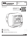
Part No. / Cód. / Art. Nr.:
383 525
HIGH FLOW U·METER 2
U·METER ALTO CAUDAL 4
U•METER MESS- UND ABSPERREINHEIT, HIGH FLOW 6
EN
ES
DE
Technical Service Guide
Guía de Servicio Técnico
Bedienungsanleitung
DOWNLOAD HERE
NEX·U·® FLUID
MANAGEMENT SYSTEM
INSTALLATION MANUAL

2838 845 R. 09/23
SAMOA Industrial, S.A. · Pol. Ind. Porceyo, I-14 · Camino del Fontán, 831 · 33392 - Gijón - Spain · Tel.: +34 985 381 488 · www.samoaindustrial.com
2023_08_23-09:30
EN
WARNINGS AND CAUTIONS
Product pictures and specifications are subject to change without prior notice.
The English version is a translation of the original document in Spanish. In case of a discrepancy, the original will prevail.
EQUIPMENT MISUSE
• This device is for professional use only. Read all instruction manuals, tags, and labels before operating the device.
• The U·meter/U·meter+ device is intended to be integrated into a fluid monitoring system.
• Do not tamper the device.
• Use the device only for its intended purpose.
• Install and use the device following all local and national regulations including all health, safety and
environmental Laws and regulations.
• Use only original spare parts kits from Samoa Industrial, S.A.
• This device has not been approved for being used in commercial transactions.
• Any unauthorised modification to the device, misuse, improper maintenance or identification label
removal may void the warranty.
• Regularly check the system components. Replace broken or worn parts.
DISPOSAL INFORMATION
The previous symbol indicates that in agreement with local laws, your product and/or your battery should
be disposed of independently of your home wastes. When this product reaches the final of its useful life,
you will need to take it to a collection point designated by the local authorities. The separate collection
and the product or battery recycling will help to protect the natural resources and guarantee its recycling
in such a way that protects the health of the people and environment.
SAFETY MEASURES
• Ensure that operators using this equipment are trained on the operation, the product and its limitations.
• Use safety equipment as required.
• To ensure the device safe operation, all service work should be done by qualified personnel only.
Disconnect the device from the mains, release the stored pressure and disconnect the equipment from
any fluid systems before carrying out any checks or replacing parts of the device.
EQUIPMENT OPERATION
• The device meter has been manufactured with tight tolerances in order to ensure high precision over a
wide range of flows and viscosity.
• Verify the correct settings of the monitoring system prior to the first use.
• Operation with flow rates close to range ends may cause a lack of accuracy of the measure. A calibration
procedure may be required in these cases.
CHEMICAL COMPATIBILITIES AND PRESSURE LIMITS
• The use of non-compatible fluids may cause damage in the device and serious personal injuries. See
technical specifications chapter.
• Do not exceed the maximum allowable working pressure of device. See TECHNICAL SPECIFICATIONS chapter.
• Do not exceed the permissible electrical ratings of the device. See TECHNICAL SPECIFICATIONS chapter.
• Observe the manufacturer’s safety warnings for the fluids used.

3
R. 09/23 838 845
SAMOA Industrial, S.A. · Pol. Ind. Porceyo, I-14 · Camino del Fontán, 831 · 33392 - Gijón - Spain · Tel.: +34 985 381 488 · www.samoaindustrial.com
2023_08_23-09:30
EN
INSTALLATION AND COMMISSIONING
SEE SPARE PARTS KITS IN PAGES 8-9
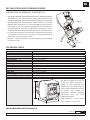
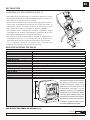
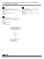
CONNECTION TO HYDRAULIC SYSTEM (FIG. 1)
• This device is designed to be installed directly into the distribution pipe line.
The meter has a 1/2” BSP connection at both inlet and outlet. It also
includes an inlet flange and an outlet flange with seating for an O-ring seal.
• Avoid installing the device between rigid connections to prevent
pipeline strain transmission. It is recommended to install a pressure
relief system on the line to prevent damage from thermal expansion.
• To prevent damage from dirt or solid particles carried by the fluid is
recommended the installation of a 200-Mesh strainer at the device inlet.
• It is advised to install the solenoid valve associated to the U-Meter
at the device inlet and not in the outlet, to avoid the device being
pressurized when the valve is closed.
• In figure 1 a typical installation is shown, which may vary according
to particular cases.
Fig. 1
FLOW
DIRECTION
TECHNICAL DATA
Metering chamber Oval gear meter
Moist part materials Aluminium, Vectra, Stainless Steel, NBR
Inlet connection 3/4" BSP
Outlet connection 3/4" BSP
Maximum working pressure 100 bar (1450 psi)
Burst pressure 150 bar (2175 psi)
Compatible fluids Oil, glycol, coolant solutions
Flow range 1-80 l/min, 0.25-21 gpm (depending on fluid viscosity and temperature)
Viscosity range 8 to 2000 cSt
Working temperature -10 ºC to 60 ºC (14 to 140 ºF)
Pressure loss at maximum flow 3 bar
Precision ±0.5% (after calibration)
Pulse ratio 109 ppl (412,6 ppg)
Power supply 24V AC/DC 50/60 Hz
Solenoid valve compatibility 24V DC (configuration needed) Maximum power 30W
Weight 800 g (1.75 lb)
Dimensions
This device complies with Part 15
of the FCC Rules. Operation is
subject to the following two
conditions: (1) this device may not
cause harmful interference, and (2)
this device must accept any
interference received, including
interference That may cause
undesired operation.
*Only applied to U meter+ model,
which comprises a wireless kit.
96 mm (3.8")
86 mm (3.4")
101 mm (3,97")

4838 845 R. 09/23
SAMOA Industrial, S.A. · Pol. Ind. Porceyo, I-14 · Camino del Fontán, 831 · 33392 - Gijón - Spain · Tel.: +34 985 381 488 · www.samoaindustrial.com
2023_08_23-09:30
ES
ADVERTENCIAS Y PRECAUCIONES
Las imágenes y especificaciones de los productos están sujetas a cambios sin previo aviso.
Documento original en español.
USO INDEBIDO DEL EQUIPO
• Este dispositivo es sólo para uso profesional. Lea atentamente el manual de instrucciones y sus
advertencias antes de empezar a operar con el equipo.
• El dispositivo U·meter/U·meter+ está destinado a integrarse en un sistema de gestión.
• No modifique el dispositivo. Utilice el dispositivo sólo para el uso para el cual fue diseñado.
• Instale y utilice el equipo de acuerdo con todas las normativas locales y nacionales incluyendo Leyes y
regulaciones en materia de salud, seguridad y medioambiente.
• Utilice solo kits de recambio originales de Samoa Industrial, S.A.
• Este dispositivo no ha sido aprobado para su empleo en transacciones comerciales.
• Cualquier modificación no autorizada del dispositivo, uso indebido, mantenimiento incorrecto o la
retirada de las etiquetas identificativas puede ser causa de anulación de la garantía.
• Verifique regularmente los componentes del sistema. Sustituya las piezas rotas o desgastadas.
INFORMACIÓN SOBRE RESIDUOS
El símbolo anterior indica que, de acuerdo con las normativas locales, su producto y/o su batería deberán
desecharse de manera independiente de los residuos domésticos. Cuando este producto alcance el final de su
vida útil, deberá llevarlo a un punto de recogida designado por las autoridades locales. La recogida separada y
el reciclaje del producto o su batería en el momento de su desecho ayudarán a proteger los recursos naturales
y a garantizar su reciclaje de forma que proteja la salud de las personas y el medio ambiente.
MEDIDAS DE SEGURIDAD
• Los fluidos no adecuados y compatibles para el dispositivo pueden causar daños al dispositivo, e implicar
riesgos y daños personales graves. Ver capítulo de especificaciones técnicas.
• No exceder la presión máxima de trabajo permitida del dispositivo. Ver capítulo de ESPECIFICACIONES TÉCNICAS.
• No exceder los rangos eléctricos permitidos del dispositivo. Ver capítulo de ESPECIFICACIONES TÉCNICAS.
• Atienda las advertencias de seguridad del fabricante de los fluidos empleados.
FUNCIONAMIENTO DEL EQUIPO
• El contador del dispositivo ha sido fabricado con reducidas tolerancias para asegurar una elevada
precisión sobre un amplio rango de caudales y viscosidad.
• Verifique la correcta configuración del sistema antes de su primer uso.
• El funcionamiento con caudales próximos a los extremos del rango de operación puede causar una
disminución de la precisión de la medición. Un proceso de calibración puede ser requerido en estos casos.
COMPATIBILIDADES QUÍMICAS Y LÍMITES DE PRESIÓN
• Los fluidos no adecuados y compatibles para el dispositivo pueden causar daños al dispositivo, e implicar
riesgos y daños personales graves. Ver capítulo de especificaciones técnicas.
• No exceder la presión máxima de trabajo permitida del dispositivo. Ver capítulo de ESPECIFICACIONES TÉCNICAS.
• No exceder los rangos eléctricos permitidos del dispositivo. Ver capítulo de ESPECIFICACIONES TÉCNICAS.
• Atienda las advertencias de seguridad del fabricante de los fluidos empleados.

5
R. 09/23 838 845
SAMOA Industrial, S.A. · Pol. Ind. Porceyo, I-14 · Camino del Fontán, 831 · 33392 - Gijón - Spain · Tel.: +34 985 381 488 · www.samoaindustrial.com
2023_08_23-09:30
ES
INSTALACIÓN
VER KITS DE RECAMBIO EN PÁGINAS 8-9
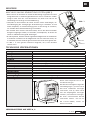
CONEXIÓN A LA RED HIDRÁULICA (FIG. 1)
• Este dispositivo está destinado a su instalación directa en la línea
de distribución de fluido. Está dotado de conexión roscada 1/2”
BSP tanto en la entrada como en la salida.
• Evite instalar el dispositivo entre conexiones rígidas para evitar la
transmisión de esfuerzos provenientes de la línea de fluido. Se
recomienda instalar un sistema de alivio de presión en la línea
para evitar causar daños por expansión térmica al equipo.
• Para prevenir daños causados por suciedad o partículas sólidas
arrastradas por el fluido se recomienda la instalación de un filtro
de al menos 200 Mesh a la entrada del dispositivo.
• Se aconseja instalar la electroválvula asociada al dispositivo a la
entrada de la misma y no a la salida para que el dispositivo no
esté sometido a presión cuando la electroválvula esté cerrada.
• En la siguiente ilustración se muestra una instalación tipo
pudiendo variar según cada instalación particular.
Fig. 1
SENTIDO
DEL FLUJO
ESPECIFICACIONES TÉCNICAS
Tipo de medidor Engranajes ovales
Materiales partes húmedas Aluminio, Vectra, Acero inoxidable, NBR
Conexión de entrada 3/4" BSP
Conexión de salida 3/4" BSP
Presión máxima de trabajo 100 bar
Presión de rotura 150 bar
Fluidos compatibles Aceite, glicol, soluciones de refrigerante
Caudal 1 a 80 l/min (0.25 - 21 gpm)(dependiendo de la viscosidad y temperatura del fluido)
Rango de viscosidad 8 a 2000 cSt
Temperatura de operación -10 ºC a 60 ºC
Pérdida de presión al caudal máximo 3 bar
Precisión ±0.5% (una vez calibrado)
Ratio de pulsos 109 ppl (412.6 ppg)
Alimentación 24V AC/DC 50/60 Hz
Compatibilidad de electroválvulas 24V DC (configuración necesaria) Potencia máxima 30W
Peso 800 g (1.75 lb)
Dimensions
Este dispositivo cumple con los estándares
RSS exentos de licencia de la Industry
Canada. Este dispositivo cumple con el
apartado 15 de la normativa de la FCC. El
funcionamiento está sujeto a las dos
condiciones siguientes: (1) este dispositivo
no podrá provocar interferencias dañinas
y (2) este dispositivo deberá aceptar todas
las interferencias recibidas, incluso aquellas
que puedan provocar un funcionamiento
no deseado. *Aplicable al modelo U meter+,
con módulo inalámbrico incorporado.
96 mm (3.8")
86 mm (3.4")
101 mm (3,97")

6838 845 R. 09/23
SAMOA Industrial, S.A. · Pol. Ind. Porceyo, I-14 · Camino del Fontán, 831 · 33392 - Gijón - Spain · Tel.: +34 985 381 488 · www.samoaindustrial.com
2023_08_23-09:30
DE
WARNUNG
Produktbilder und Spezifikationen können ohne vorherige Ankündigung geändert werden. Die deutsche Fassung ist
eine Übersetzung des spanischen Originaldokuments. Im Falle einer Abweichung ist die Originalfassung maßgebend.
FALSCHE VERWENDUNG DER AUSRÜSTUNG
• Dieses Gerät ist nur für den professionellen Gebrauch bestimmt. Lesen Sie die Gebrauchsanweisung und
die darin enthaltenen Warnhinweise sorgfältig durch, bevor Sie das Gerät in Betrieb nehmen.
• Das U·meter/U·meter+ Gerät ist für die Integration in ein Flüssigkeitsüberwachungssystem vorgesehen.
• Die Unversehrtheit des Geräts darf nicht beeinträchtigt werden.
• Verwenden Sie die Ausrüstung nur für den Zweck, für den sie bestimmt ist.
• Installieren und verwenden Sie die Ausrüstung unter Einhaltung aller örtlichen und nationalen
Vorschriften, einschließlich aller Gesundheits- und Sicherheitsgesetze und -bestimmungen.
• Verwenden Sie nur Original-Austauschkits von Samoa Industrial, S.A.
• Dieses Gerät ist nicht für den Einsatz im Handel zugelassen.
• Jegliche unbefugte Veränderung des Geräts, Missbrauch, unsachgemäße Wartung oder Entfernung von
Kennzeichnungsschildern kann zum Erlöschen der Garantie führen.
• Überprüfen Sie regelmäßig die Systemkomponenten. Ersetzen Sie defekte oder verschlissene Teile.
INFORMATIONEN ZUR ABFALLENTSORGUNG
Das obige Symbol weist darauf hin, dass Ihr Produkt und/oder Ihre Batterie gemäß den örtlichen Vorschriften getrennt
vom Hausmüll entsorgt werden muss. Wenn dieses Produkt das Ende seiner Nutzungsdauer erreicht hat, sollten Sie es
zu einer von den örtlichen Behörden bestimmten Sammelstelle bringen. Die getrennte Sammlung und das Recycling
des Produkts bzw. der Batterie bei der Entsorgung tragen zum Schutz der natürlichen Ressourcen bei und
gewährleisten, dass das Produkt auf eine Weise recycelt wird, die die menschliche Gesundheit und die Umwelt schützt.
SICHERHEITSMASSNAHMEN
• Stellen Sie sicher, dass die Bediener, die diese Ausrüstung benutzen, in Bezug auf den Betrieb, das
Produkt und seine Grenzen geschult sind.
• Verwenden Sie die erforderliche Sicherheitsausrüstung. Um einen sicheren Betrieb des Geräts zu
gewährleisten, sollten alle Wartungsarbeiten nur von qualifiziertem Personal durchgeführt werden.
Trennen Sie das Gerät vom Netz, lassen Sie den gespeicherten Druck ab und trennen Sie das Gerät von
allen Flüssigkeitssystemen, bevor Sie Kontrollen durchführen oder Teile des Geräts auswechseln.
GERÄTEBETRIEB
• Dieses Messgerät wurde mit engen Toleranzen hergestellt, um eine hohe Präzision über einen weiten
Bereich von Durchflussraten und Viskositäten zu gewährleisten.
• Überprüfen Sie die korrekten Einstellungen des Überwachungssystems vor dem ersten Einsatz.
• Der Betrieb mit Durchflussraten nahe am Bereichsende kann zu einer mangelnden Genauigkeit der
Messung führen. In diesen Fällen kann ein Kalibrierungsverfahren erforderlich sein.
CHEMISCHE KOMPATIBILITÄTEN UND DRUCKGRENZEN
• Für die Ausrüstung ungeeignete Flüssigkeiten können zu Schäden am Gerät führen und ein Risiko für
schwere Verletzungen darstellen. Siehe Kapitel “Technische Daten”.
• Überschreiten Sie nicht den maximal zulässigen Betriebsdruck des Geräts. Siehe Kapitel “TECHNISCHE DATEN”.
• Die zulässigen elektrischen Nennwerte des Geräts dürfen nicht überschritten werden. Siehe Kapitel “TECHNISCHE DATEN”.
• Beachten Sie die Sicherheitshinweise des Herstellers der verwendeten Flüssigkeiten.

7
R. 09/23 838 845
SAMOA Industrial, S.A. · Pol. Ind. Porceyo, I-14 · Camino del Fontán, 831 · 33392 - Gijón - Spain · Tel.: +34 985 381 488 · www.samoaindustrial.com
2023_08_23-09:30
DE
MONTAGE
SIEHE ERSATZTEILE AUF SEITE 8, 9
ANSCHLUSS AN DAS ROHRLEITUNGSSYSTEM (ABB.1)
• Dieses Gerät ist zur Installation im Verlauf der Rohrleitung vorgesehen. Das Gerät
verfügt über einen ½“-BSPInnengewindeanschluss am Ein- und Auslass. Zudem
verfügt es über einen Ein- und Auslassflansch mit jeweils einer Nut für die
Verwendung eines O-Rings zur Flanschabdichtung.
• Vermeiden Sie die Installation des Geräts zwischen starren Verbindungen, um
eine Übertragung der Schwingungen der Rohrleitung zu verhindern. Es wird
zudem empfohlen, ein Druckentlastungssystem an der Leitung zu installieren,
um Schäden durch Wärmeausdehnung zu vermeiden.
• Um Schäden durch Schmutz oder feste Partikel, die von der durchströmenden
Flüssigkeit eingetragen werden, zu vermeiden, wird empfohlen, am Einlass des
Geräts ein 200 Mesh-Leitungssieb anzubringen.
• Es wird empfohlen, das dem U-Meter zugeordnete Magnetventil am Geräteeinlass
zu installieren. Installieren Sie das Magnetventil nicht am Auslass des Geräts, um
zu vermeiden, dass das Gerät bei geschlossenem Ventil unter Druck gesetzt wird.
• In Abb. 1 ist eine typische Installation dargestellt, die je nach Einzelfall
variieren kann.
Abb. 1
RICHTUNG
DER
STRÖMUNG
TECHNISCHE SPEZIFIKATIONEN
Zählertyp Ovalzahnrad
Medienberührte Bauteile Aluminium, Vectra, Edelstahl, NBR
Einlassgewinde 3/4" BSP IG
Auslassgewinde 3/4" BSP IG
Arbeitsdruck max. 100 bar (1450 psi)
Berstdruck 150 bar (2175 psi)
Kompatible Medien Öl, Glykol, Kühlflüssigkeiten
Durchflussrate 1 bis 80 l/min (abhängig von Viskosität und Temperatur) (0,25 bis 21 gal/min)
Viskositätsbereich 8 bis 2.000 cSt
Einsatztemperatur -10 ºC bis 60 ºC (14 ºF bis 140 ºF)
Druckverlust bei max. Durchfluss 3 bar (43,5 psi)
Genauigkeit ±0,5% (nach Kalibrierung)
Impulswertigkeit 109 ppl (412.6 ppg), Doppelkanal
Stromversorgung 24V AC
Spannung Magnetventil 24V DC and AC. Max. Leistung für Magnetventil 30W
Gewicht 500g (1.1 lb)
Abmessungen
Dieses Gerät entspricht Teil 15 der
FCC-Bestimmungen.
Der Betrieb unterliegt den folgenden
zwei Bedingungen: (1) Dieses Gerät
darf keine schädlichen Störungen
verursachen, und (2) dieses Gerät
muss alle empfangenen Störungen
tolerieren, einschließlich Störungen,
die einen unerwünschten Betrieb
verursachen können. *Gilt nur für
das U·meter+-Modell, welches ein
Wireless-Kit enthält.
96 mm (3.8")
86 mm (3.4")
101 mm (3,97")

8838 845 R. 09/23
SAMOA Industrial, S.A. · Pol. Ind. Porceyo, I-14 · Camino del Fontán, 831 · 33392 - Gijón - Spain · Tel.: +34 985 381 488 · www.samoaindustrial.com
2023_08_23-09:30
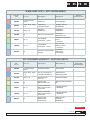
EN ES FR DE
Kit Nº
369625
Kit Nº
369645
382909
Kit Nº
Kit Nº
738238
738901
Kit Nº
Kit Nº
738902
838244
Kit Nº
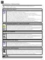
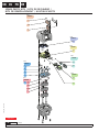
1
2
3
5
4
6
7
8
9
10
11
17
14
15
16
8
12
13
Ctd.
Código
Code
Denominación
Denomination
Marca
Pos.
Observaciones
Observations
1
836927
Envase cartón P/Cont. electrónico GC
53
/K3-P4-K3
1
838617
Carátula IFCU ND
52
Poliester texturado
1
838667
Adhesivo tapa pilas Samoa
51
Soporte adhesivo
2
945028
Tapón protector roscado 3/4"
50
Comercial
2
946172
Junta tórica 25.1x1.5 NBR70
49
/NBR 70 Shore A
2
951977
Jumper con lengüeta
48
Comercial
1
838615
Tapa embellecedor IFCU
47
/Xenoy 5220U
2
838618
Tapón CAN BUS
46
Polipropileno
1
838614
Cuerpo carcasa contador
45
Material: Policarbonato Lexan 500R
1
838503
Burlete conexiones IFCU ND
44
Espesor 2 mm/PE celular
1
838502
Separador espuma EVA 13x2
43
Espesor 2 mm/PE celular
1
838438
Pletina conexión a masa
42
Fleje espesor 0.5 mm/Fleje de acero inoxidable
1
838244_8 41
-
4
838244_7 40
1
838244_6 39
-
2
838244_5 38
1
838244_4 37
-
1
838244_3 36
-
1
838244_2 35
-
2
896652
Soporte reed
34
/Polipropileno
1
838245_9 33
--/Material <sin especificar>
2
838245_8 32
-
1
838245_7 31
-
1
838245_6 30
--/Material <sin especificar>
1
838245_5 29
--/Material <sin especificar>
1
838245_4 28
-
1
838245_3 27
-
2
838245_2 26
-
2
836200_5
Reed switch
25
Comercial
1
838613
Carcasa IFCU ND
24
Xenoy 5220U - Negro text. VD
1
-
Etiqueta de características plata
23
IMPRIMIR EN SAMOA
2
940900
Tornillo Av. inox M4x12 DIN-7991
22
Comercial
2
896426
Eje engranajes - GC
21
AISI 316
4
940524
Tornillo alomado p/plástico 3,1x8
20
Comercial
4
940523
Tornillo p/plastico 4,6x16
19
Comercial. ACERO
1
736113
Cámara de medición - GC
18
Aluminio EN AC-46500 (L-2630)
1
951892
Conector macho 5 polos acodado
17
Comercial
1
951893
Carcasa conector 5 polos
16
--/Material <sin especificar>
1
951979
Carcasa conector 2 polos
15
Comercial
1
951978
Conector macho 2 polos
14
Comercial
1
838245_1 13
-
1
838244_1 12
-
4
896427
Eje union engranajes
11
AISI 316
6
836600
Engranaje oval cont. ND
10
Delrin 500
4
836467
Imán 4x5 (neodimio)
9
Comercial
1
946137
Junta tórica 54x1.5 NBR70
8
Comercial
1
836114
Tapa cámara de medición c/agujeros
7
Aluminio L-2561
2
946096
Junta tórica 4X1.2 NBR 75
6
Comercial
8
940200
Tornillo Av. ex. int. M4x14 DIN-7991
5
Comercial
2
940205
Tornillo TORX M4x10 FLANGE ISO-7380 AISI 304
4
Comercial
1
838247
Tarjeta RFI
3
PCBA
1
838619
Cuerpo carcasa contador
2
Material: Policarbonato Lexan 500R
6
940525
Tornillo av. p/plástico 3,1x10 negro
1
Comercial
REPLACEMENT KITS / KITS DE RECAMBIO
Part nº / Cód
Samoa Industrial, S.A.
P.O. Box 103 E-33200 Gijón (Asturias) Spain www.samoaindustrial.com
1/2
HIGH FLOW U·METER, HIGH FLOW U·METER+
U·METER ALTO CAUDAL, U·METER+ ALTO CAUDAL
383525
383526
NEXU04.B
27/05/2022
SPARE PARTS KITS / KITS DE RECAMBIO /
KITS DE REMPLACEMENT / AUSTAUSCHKITS
NEXU04.C

9
R. 09/23 838 845
SAMOA Industrial, S.A. · Pol. Ind. Porceyo, I-14 · Camino del Fontán, 831 · 33392 - Gijón - Spain · Tel.: +34 985 381 488 · www.samoaindustrial.com
2023_08_23-09:30
EN ES FR DE
SPARE PARTS KITS / KITS DE RECAMBIO
Part No.
Cód. Incl. Pos. Description Descripción Remarks
Observaciones
369625 8, 4x(9), 6x(10),
4x(11) Gears Kit Kit Engranajes -
369645 2x(4), 8x(5), 2x(6),
7, 8
Measuring
Chamber Lid Kit
Kit tapa Cámara
de Medición -
381909 2x(1), 2, 3 Wireless
Module Kit
Kit Módulo
Inalámbrico -
738238 13 Electronic CPI Card Kit Kit Tarjeta
Electrónica CPI -
738901 16, 17 5-Pole Male
Connector + Cover
Kit Conector Macho 5
Polos
+ Carcasa
-
738902 14, 15 2-Pole Male
Connector + Cover
Kit Conector
Macho 2 Polos
+ Carcasa
-
838244 12 Electronic Card Kit with
Display
Kit Tarjeta
Electrónica
con Display
-
KITS DE REMPLACEMENT / AUSTAUSCHKITS
Réf.
Art. Nr. Incl. Pos. Description Beschreibung Remarques
Bemerkungen
369625 8, 4x(9), 6x(10),
4x(11) Kit d'Engrenages Zahnradsatz -
369645 2x(4), 8x(5), 2x(6),
7, 8
Kit de Couvercle de
Chambre de Mesure
Messkammer-
Abdeckungssatz -
381909 2x(1), 2, 3 Kit de Module
sans Fil Drahtloses Modul -
738238 13 Kit de Carte
Électronique CPI
Elektronische CPI Karte
Kit -
738901 16, 17
Kit de Connecteur
Male avec 5 Pôles +
Couvercle
5-Poliger Stecker
+ Gehäuse -
738902 14, 15
Kit de Connecteur
Male avec 2 Pôles +
Couvercle
2-Poliger Stecker
+ Gehäuse -
838244 12
Kit de Carte
Électronique
avec Display
Elektronische
Karte Kit
Mit Display
-
NEXU04.C

10 838 845 R. 09/23
SAMOA Industrial, S.A. · Pol. Ind. Porceyo, I-14 · Camino del Fontán, 831 · 33392 - Gijón - Spain · Tel.: +34 985 381 488 · www.samoaindustrial.com
2023_08_23-09:30
NOTES / NOTAS / NOTIZEN

11
R. 09/23 838 845
SAMOA Industrial, S.A. · Pol. Ind. Porceyo, I-14 · Camino del Fontán, 831 · 33392 - Gijón - Spain · Tel.: +34 985 381 488 · www.samoaindustrial.com
2023_08_23-09:30
NOTES / NOTAS / NOTIZEN

12 838 845 R. 09/23
SAMOA Industrial, S.A. · Pol. Ind. Porceyo, I-14 · Camino del Fontán, 831 · 33392 - Gijón - Spain · Tel.: +34 985 381 488 · www.samoaindustrial.com
2023_08_23-09:30
SAMOA INDUSTRIAL, S.A., Pol. Ind. Porceyo, I-14 ·
Camino del Fontán, 831 · 33392 - Gijón - Spain, declares
that the product(s):
383 525
conform(s) with the EU Directive(s):
2014/30/EC
EN
SAMOA INDUSTRIAL, S.A., Pol. Ind. Porceyo, I-14 ·
Camino del Fontán, 831 · 33392 - Gijón - España,
declara que el(los) producto(s):
383 525
cumple(n) con la(s) Directiva(s) de la Unión Europea:
2014/30/CE
ES
SAMOA INDUSTRIAL, S.A., Pol. Ind. Porceyo, I-14 ·
Camino del Fontán, 831 · 33392 - Gijón- Spanien,
bestätigt hiermit, dass das (die) Produkt (e):
383 525
der (den) EG-Richtlinie(n):
2014/30/EG
entspricht (entsprechen).
DE
EC CONFORMITY DECLARATION / DECLARATION CE DE CONFORMIDAD /
EG-KONFORMITÄTSERKLÄRUNG
For SAMOA INDUSTRIAL, S.A.
Por SAMOA INDUSTRIAL, S.A.
Für SAMOA INDUSTRIAL, S.A.
Pedro E. Prallong Álvarez
Production Director
Director de Producción
Produktionsleiter
-
 1
1
-
 2
2
-
 3
3
-
 4
4
-
 5
5
-
 6
6
-
 7
7
-
 8
8
-
 9
9
-
 10
10
-
 11
11
-
 12
12


in anderen Sprachen
- English: Samoa 383525
- español: Samoa 383525
Verwandte Artikel
-
Samoa 383520 Instructions Manual
-
-
-
-
-
-
-
-
-