Bresser 7003350 Bedienungsanleitung
- Kategorie
- Wetterstationen
- Typ
- Bedienungsanleitung

WIFI Colour Weather Center
Art. No. 7003350
GB
INSTRUCTION MANUAL
DE
BEDIENUNGSANLEITUNG

DE Besuchen Sie unsere Website über den folgenden QR Code oder Weblink um weitere Informationen
zu diesem Produkt oder die verfügbaren Übersetzungen dieser Anleitung zu nden.
EN Visit our website via the following QR Code or web link to nd further information on this product
or the available translations of these instructions.
FR Si vous souhaitez obtenir plus d’informations concernant ce produit ou rechercher ce mode
d’emploi en d’autres langues, rendez-vous sur notre site Internet en utilisant le code QR ou le lien
correspondant.
NL Bezoek onze internetpagina via de volgende QR-code of weblink, voor meer informatie over dit
product of de beschikbare vertalingen van deze gebruiksaanwijzing.
ES ¿Desearía recibir unas instrucciones de uso completas sobre este producto en un idioma
determinado? Entonces visite nuestra página web utilizando el siguiente enlace (código QR) para
ver las versiones disponibles.
IT Desidera ricevere informazioni esaustive su questo prodotto in una lingua specica? Venga a
visitare il nostro sito Web al seguente link (codice QR Code) per conoscere le versioni disponibili.
https://www.wunderground.comhttps://weathercloud.net
WORKS WITH:
APP DOWNLOAD:
Apple and the Apple logo are trademarks of Apple Inc., registered in the U.S.
and other countries. App Store is a service mark of Apple Inc., registered in the
U.S. and other countries.
Google Play and the Google Play logo are trademarks of Google Inc.
www.bresser.de/warranty_terms
https://proweatherlive.net https://www.awekas.at
AWEKAS
Weather Underground is a registered trademark of The Weather Channel, LLC. both in the United States and internationally. The Weather Underground Logo is a
trademark of Weather Underground, LLC. Find out more about Weather Underground at www.wunderground.com

GB
Instruction manual .............................4
DE
Bedienungsanleitung .......................38

4
TABLE OF CONTENTS
1. INTRODUCTION ..................................................................6
1.1 QUICK START GUIDE ......................................................... 7
2. PRE INSTALLATION ...............................................................7
2.1 CHECKOUT .................................................................. 7
2.2 SITE SELECTION . . . . . . . . . . . . . . . . . . . . . . . . . . . . . . . . . . . . . . . . . . . . . . . . . . . . . . . . . . . . . 7
3. GETTING STARTED ...............................................................8
3.1 WIRELESS 5-IN-1 SENSOR ..................................................... 8
3.1.1 INSTALL WIND VANE ....................................................8
3.1.2 INSTALL RAIN GAUGE FUNNEL ...........................................9
3.1.3 INSTALL BATTERIES ....................................................9
3.1.4 SENSOR ARRAY INSTALLATION . . . . . . . . . . . . . . . . . . . . . . . . . . . . . . . . . . . . . . . . . .9
3.1.5 DIRECTION ALIGNMENT ................................................11
3.1.6 POINTING THE WIRELESS 5-IN-1 SENSOR TO SOUTH .....................11
3.2 RECOMMENDATION FOR BEST WIRELESS COMMUNICATION .................... 11
3.3 SETUP THE CONSOLE ....................................................... 12
3.3.1 POWERING UP THE CONSOLE ..........................................12
3.3.2 SETUP DISPLAY CONSOLE .............................................13
3.3.3 SYNCHRONIZING WIRELESS 5-IN-1 SENSOR ARRAY ......................13
3.3.4 DATA CLEARING .......................................................13
4. DISPLAY CONSOLE FUNCTIONS AND OPERATION ...................................14
4.1 SCREEN DISPLAY ........................................................... 14
4.2 DISPLAY CONSOLE KEYS .................................................... 14
4.3 CONSOLE FEATURES ........................................................ 15
4.3.1 WEATHER FORECAST .................................................15
4.3.2 BAROMETRIC PRESSURE ..............................................15
4.3.3 OUTDOOR TEMPERATURE, HUMIDITY ...................................16
4.3.4 OUTDOOR TEMPERATURE INDEX .......................................16
4.3.5 INDOOR TEMPERATURE & HUMIDITY ....................................17
4.3.6 WIND ................................................................17
4.3.7 RAIN .................................................................19
4.3.8 MAXIMUM / MINIMUM RECORDS ........................................19
4.3.9 MOON PHASE .........................................................20
4.3.10 WIRELESS SENSOR SIGNAL RECEIVING .................................20
4.3.11 TIME SYNCHRONIZE STATUS ...........................................20
4.3.12 WI-FI CONNECTION STATUS ............................................20
4.4 OTHER SETTING ............................................................ 21
4.4.1 TIME, DATE, UNIT AND OTHER SETTING .................................21
4.4.2 SETTING ALARM TIME AND HIGH / LOW WEATHER ALERT ..................21
4.4.3 BACK LIGHT ..........................................................23
5. CONNECT CONSOLE TO WI-FI ..................................................... 23
5.1 DOWNLOAD WSLINK CONFIGURATION APP .................................... 23
5.2 CONSOLE IN ACCESS POINT MODE ........................................... 23
5.3 ADD YOUR CONSOLE TO WSLINK ............................................. 24
5.4 SETUP NEW CONSOLE WITH WSLINK ......................................... 25
5.5 WEATHER SERVER SETTING ................................................. 26
5.6 CALIBRATION ............................................................... 27
5.7 FIRMWARE ................................................................. 27
6. CREATE WUNDERGROUND & WEATHERCLOUD ACCOUNT ...........................28
6.1 FOR WEATHER UNDERGROUND (WU) ......................................... 28
6.2 FOR WEATHERCLOUD (WC) .................................................. 30
7. VIEW WUNDERGROUND & WEATHERCLOUD LIVE DATA ..............................31
7.1 VIEW YOUR WEATHER DATA IN WUNDERGROUND .............................. 31
7.2 VIEWING YOUR WEATHER DATA IN WEATHERCLOUD ............................ 31
7.3 VIEWING WEATHER DATA VIA WSLINK APP ..................................... 32
8. MAINTENANCE ..................................................................32
8.1 FIRMWARE UPDATE ......................................................... 32
8.1.1 FIRMWARE UPDATE STEP ..............................................32

5
ABOUT THIS USER’S MANUAL
This symbol represents a warning. To ensure safe use, always adhere to the
instructions described in this documentation.
This symbol is followed by a user’s tip.
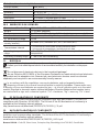
PRECAUTIONS
- Keeping and reading the “User manual” is highly recommended. The manufacturer and supplier cannot
accept any responsibility for any incorrect readings, export data lost and any consequences that occur
should an inaccurate reading take place.
- Images shown in this manual may dier from the actual display.
- The contents of this manual may not be reproduced without the permission of the manufacturer.
- Technical specications and user manual contents for this product are subject to change without notice.
- This product is not to be used for medical purposes or for public information
- Do not subject the unit to excessive force, shock, dust, temperature or humidity.
- Do not cover the ventilation holes with any items such as newspapers, curtains etc.
- Do not immerse the unit in water. If you spill liquid over it, dry it immediately with a soft, lint-free cloth.
- Do not clean the unit with abrasive or corrosive materials.
- Do not tamper with the unit’s internal components. This invalidates the warranty.
- Placement of this product on certain types of wood may result in damage to its nishing for which
manufacturer will not be responsible. Consult the furniture manufacturer’s care instructions for information.
- Only use attachments / accessories specied by the manufacturer.
- This product is not a toy. Keep out of the reach of children.
- The console is intended to be used only indoors.
- Place the console at least 20cm from nearby persons.
- Console working temperature: -5˚C ~ 50˚C
WARNING
- Do not ingest the battery. Chemical Burn Hazard.
- This product contains a coin/key cell battery. If the coin/key cell battery is swallowed, it can cause severe
internal burns in just 2 hours and can lead to death.
- Keep new and used batteries apart. If battery door does not close securely, stop using the product and
keep it away from children.
- If you think batteries might have been swallowed or placed inside any part of the body, seek immediate
medical attention.
- An appliance is only suitable for mounting at height ≤ 2m. (Equipment mass ≤1kg)
- This product is intended for use only with the adaptor provided:
Manufacturer: Dong Guan Shi Jie Hua Xu Electronics Factory
Model: HX075-0501000-AB, HX075-0501000-AG-001 or HX075-0501000-AX
8.2 BATTERY REPLACEMENT .................................................... 33
8.2.1 RE-PAIRING THE SENSOR ARRAY MANUALLY .............................33
8.3 RESET AND FACTORY RESET ................................................. 33
8.4 WIRELESS 5-IN-1 SENSOR ARRAY MAINTENANCE ............................... 33
9. TROUBLESHOOT ................................................................34
10. SPECIFICATIONS ................................................................34
10.1 CONSOLE .................................................................. 34
10.2 WIRELESS 5-IN-1 SENSOR .................................................... 36
11. DISPOSAL ......................................................................36
12. EC DECLARATION OF CONFORMITY ...............................................36
13. UKCA DECLARATION OF CONFORMITY .............................................36
14. WARRANTY & SERVICE ........................................................... 37

6
- When disposing of this product, ensure it is collected separately for special treatment.
- The AC/DC adaptor is used as disconnect device.
- The AC/DC adaptor of apparatus should not be obstructed OR should be easily accessed during intended
used.
- To be completely disconnect the power input, the AC/DC adaptor of apparatus shall be disconnected from
the mains.
CAUTION
- Danger of explosion if battery is incorrectly replaced. Replace only with the same or equivalent type.
- Battery cannot be subjected to high or low extreme temperatures, low air pressure at high altitude during
use, storage or transportation.
- Replacement of a battery with an incorrect type can result in an explosion or the leakage of ammable
liquid or gas.
- Disposal of a battery into re or a hot oven, or mechanically crushing or cutting of a battery, can result in an
explosion.
- Leaving a battery in an extremely high temperature surrounding environment can result in an explosion or
the leakage of ammable liquid or gas.
- A battery subjected to extremely low air pressure may result in an explosion or the leakage of ammable
liquid or gas.
1. INTRODUCTION
Thank you for selecting WI-FI weather station with 5-in-1 professional sensor. This system
gathers and automatically uploads accurate and detailed weather data to Weather Underground
, Weathercloud website and 3rd partly weather platform which you can access and upload your
weather data freely. This product oers professional weather observers and with exclusive app
for easy setup. You will get your own local forecast, high / low, totals and averages for virtually
all weather variables without using a PC / Mac. This Weather Station which transmits wireless
sensor array's temperature, humidity, wind and rain data to the console. This sensor array is
fully assembled and calibrated for your easy installation. It can send data at a low power radio
frequency to the console from up to 150m / 450 feet away (line of sight).
In the console, a high-speed processor is embedded to analyze the received weather data and
these real time data can be published to the weather platforms through your home WI-FI router.
The console can also synchronize with Internet time server to keep the time and weather data
time stamp of high precision. The color background LCD display shows informative weather
readings with advanced features, such as high/low alert alarm, dierent weather index, and
MAX / MIN records. With calibration and moon phase feature, this system is truly a remarkably
personal yet professional weather station for your own backyard.

7
1.1 QUICK START GUIDE
The following Quick Start Guide provides the necessary steps to install and operate the weather
station, and upload to the Internet, along with references to the pertinent sections.
Step Description Section
1 Power up the 5-in-1 wireless sensor array 3.1.3
2 Power up the display console and pair with sensor array 3.3
3 Manually set date and time (This part is unnecessary if the weather
station is connected to internet and time synchronize function is on) 4.4.1
4 Reset the rain to zero 4.3.7.2
5 Create account and register weather station at WUnderground and/
or Weathercloud 6
6 Connect weather station to WI-FI 5
2. PRE INSTALLATION
2.1 CHECKOUT
Before permanently install your weather station, we recommend the user to operate the weather
station at a location which is easy to access to. This will allow you to get familiar with the
weather station functions and calibration procedures, to ensure proper operation before installing
it permanently.
2.2 SITE SELECTION
Before installing the sensor array, please consider the followings;
1. Rain gauge must be clean every few months
2. Batteries must be changed every 2 to 2.5 years
3. Avoid radiant heat reected from any adjacent buildings and structures. Ideally, the sensor
array should be installed at 1.5m (5’) from any building, structure, ground or roof top.
4. Choose an area of open space in direct sunlight without any obstruction of rain, wind, and
sunlight.
5. Transmission range between sensor array and display console could reach a distance of
150m (or 450 feet) at line of sight, providing there are no interfering obstacles in between or
nearby such as trees, towers, or high voltage line. Check the reception signal quality to ensure
good reception.
6. Household appliance such as fridge, lighting, dimmers may pose Electro-magnetic
interference (EMI), while Radio Frequency Interference (RFI) from devices operating in the
same frequency range may cause signal intermittent. Choose a location at least 1-2 meter
(3-5 feet) away from these interference sources to ensure best reception.

8
3. GETTING STARTED
3.1 WIRELESS 5-IN-1 SENSOR
2
3
5
1
4
6
8
7
11
12
10
13
14
9
1. Rain collector
2. Balance indicator
3. Solar panel
4. Wind vane
5. Wind cups
6. Antenna
7. Mounting clamp
8. Radiation shield and
thermo-hygro sensor
9. Red LED indicator
10. [ RESET ] key
11. Battery door
12. Drain holes
13. Rain sensor
14. Tipping bucket
3.1.1 INSTALL WIND VANE
With reference to photo below, follow the steps below.
Step 1: Locate and align the at are on the wind vane shaft to the at surface on the wind vane
and push the vane onto the shaft.
Step 2: Tighten the set screw with a precision screwdriver.
Step 1 Step 2

9
3.1.2 INSTALL RAIN GAUGE FUNNEL
Install the rain gauge funnel and rotate clockwise to lock the funnel to the sensor array
Lock
grooves
Step 1
Step 2
3.1.3 INSTALL BATTERIES
Unscrew the battery door at bottom of unit. Insert the 3 AA batteries (non-rechargeable)
according to the +/- polarity indicated. The red LED indicator on the back of the sensor array
will turn on, and then begin ashing every 12 seconds.
NOTE:
We recommend using non-rechargeable Lithium AA batteries for cold weather climate, but
normally Alkaline batteries are sucient for use in most weather condition.
3.1.4 SENSOR ARRAY INSTALLATION
Mounting kit set
1. Pole mounting stand x 1 2. Mounting clamp x 1 3. Plastic pole x 1
4. screws x 4 5. Hex nuts x 4 6. Flat washers x 4
7. screw x 1 8. Hex nut x 1 9. Rubber pads x 2

10
PLASTIC MOUNTING INSTALLATION
1. Fasten the plastic pole onto your x pole with mounting base, clamp, washers, screws and
nuts. Following below 1a, 1b, 1c sequences:
1a. Insert the plastic pole into the hole of the
mounting stand, and then secure it with the screw
and nut.
1c. Fasten the mounting stand
and clamp together onto a x
pole with 4 long screws and
nuts.
1b. Apply 2 rubber pads on the mounting clamp.
2. Apply 2 rubber pads on the inner
sides of the mounting base and
clamp of the sensor-array, and
loosely fasten them together.
3. Place the sensor-array over the mounting pole
and align it to North direction before fastening the
screws.

11
NOTE:
- Any metal object can attract lightning strikes, including your sensor-array mounting pole. Never install
sensor-array in stormy days.
- If you want to install a sensor-array on a house or building, consult a licensed electrical engineer to
ensure proper grounding. Direct lightning impact on a metal pole can damage or destroy your home.
- Installing the sensor at high location may result in personal injury or death. Perform as many initial
inspections and operations as possible on the ground and in buildings or houses. Only install the sensor-
array on clear, dry days.
3.1.5 DIRECTION ALIGNMENT
Install the wireless 5-in-1 sensor in an open location
with no obstructions above and around the sensor
for accurate rain and wind measurement.
Locate the North (N) marker on top of the 5-in-1
sensor and align the marker to point North upon
nal installation with a compass or GPS. Tighten the
mounting bracket around a 30 to 40 mm diameter
pole (not included) using two screw and nuts
provided.
North marker on top of the 5-in-1 sensor.
Use the bubble level on the 5-in-1 sensor to make
sure the sensor is completely level for proper
measurement of rainfall.
2 meters o the ground
Mounting pole
not included
3.1.6 POINTING THE WIRELESS 5-IN-1 SENSOR TO SOUTH
The outdoor 5-in-1 sensor is calibrated to point to North for the maximum accuracy. However,
for the user's convenience (e.g. users in the Southern hemisphere), it is possible to use the
sensor with the wind vane pointing to South.
1. Install the 5-in-1 wireless sensor with its wind meter end pointing to South. (Please refer to
section 3.1.4 for mounting details)
2. Select "S' in set hemisphere step (Please refer to section 4.4.1 for setup details)
3. Follow the setup procedure to conrm and exit.
NOTE:
Changing the hemisphere setting will automatically switch the direction of the moon phase on
the display.
3.2 RECOMMENDATION FOR BEST WIRELESS COMMUNICATION
Eective wireless communication is susceptible to noise interference in the environment, and
distance and barriers between the sensor transmitter and the display console.

12
1. Electromagnetic interference (EMI) may be generated by machinery, appliances, lighting,
dimmers and computers, etc. To avoid this, keep your console 1 or 2 meters away from
these items.
2. Radio-frequency interference (RFI): if you have other devices operating on 868 / 915 / 917
MHz, you might experience communication intermittent. Please re-located your transmitter
or display console to avoid signal intermittent problem.
3. Path loss occurs naturally with increasing distance. This device is rated to 150m (450 feet)
by line of sight (in interference free environment and without barriers). However, typically
you will get 30m (100 feet) maximum in real life installation, which includes passing through
barriers.
4. Radio signal are blocked by metal barriers such as aluminum cladding. Please align the
sensor array and display console to get them in clear line of sight through window if you
have metal cladding.
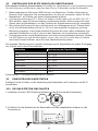
The table below show a typical level of reduction in signal strength each time the signal passed
through these building materials
Materials Signal strength reduction
Glass (untreated) 10 ~ 20%
Wood 10 ~ 30%
Plasterboard / drywall 20 ~ 40%
Brick 30 ~ 50%
Foil insulation 60 ~ 70%
Concrete wall 80 ~ 90%
Aluminum siding 100%
Metal wall 100%
Remarks: RF signal reduction for reference
3.3 SETUP THE CONSOLE
Follow the procedure to setup the console connection with wireless sensor array and WI-FI.
3.3.1 POWERING UP THE CONSOLE
1. Install the back-up CR2032 battery on the console's backside.
2. Connect the display console power jack to AC power with the adaptor included.
SENSOR
REFRESH
CONTRAST
RESET
WI-FI
DC5V 1A
NOTE:
- The backup battery can backup: Time & Date & Max/Min weather records, rainfall records and Alert
setting values / status.

13
- The built-in memory can backup: WI-FI setting, Hemisphere setting, Calibration values, and Sensor ID.
- Please always remove the back-up battery if the device is not going to be used for a while. Please keep
in mind that even when the device is not in use, certain settings, such as the clock, alert settings and
records in its memory, will still drain the back-up battery.
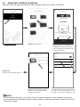
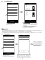
3.3.2 SETUP DISPLAY CONSOLE
1. Once the console power up, all the segments of the LCD will be shown.
2. The console will automatically start AP mode and show the "AP" icon on the screen, you
can follow the Section 5 to setup the WI-FI connection.
Start up screen (with 5-in-1 sensor connected)
NOTE:
If no display appears when power up the console, you can press [ RESET ] key by using a pointed object.
If this process still not work, you can remove the backup battery and unplug the adapter then re-power up
the console again.
3.3.3 SYNCHRONIZING WIRELESS 5-IN-1 SENSOR ARRAY
Immediately after power up the console, while still in synchronization mode, the 5-in-1 sensor
can be paired to the console automatically (as indicated by the ashing antenna ). User may
also manually restart the synchronization mode by pressing the [ SENSOR / WI-FI ] key. Once
they are paired up, the sensor signal strength indicator and weather reading will appear on your
console display.
3.3.4 DATA CLEARING
During installation of the wireless 5-in-1 sensor, the sensors were likely to be triggered,
resulting in erroneous rainfall and wind measurements. After the installation, user may clear
out all the erroneous data from the display console. Simply press the [ RESET ] key once to
re-start the console.

14
4. DISPLAY CONSOLE FUNCTIONS AND OPERATION
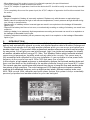
4.1 SCREEN DISPLAY
12
45
67
3
1. Outdoor temperature & humidity
2. Wind speed & direction
3. Rain rate & rainfall
4. In temperature & humidity
5. Weather forecast & pressure
6. Moon phase, time & date
7. Outdoor temperature index
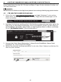
4.2 DISPLAY CONSOLE KEYS
5
6
7
8
9
10 11 12 13 14 15 16 17
SENSOR
REFRESH
CONTRAST
RESET
WI-FI
DC5V 1A
1
2
3
4
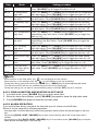
No. Key / Part Name Description
1BACK LIGHT /
SNOOZE Press to change the back light level or stop alarm sound
2MEMORY Press to switch between maximum and minimum values of Daily and
Since last reset
3ALARM During alarm, press to stop the alarm, press and hold for 2 seconds
to stop current snooze
4SET Hold to enter time and date setting
5INDEX To switch between feels like, heat index, dew point and wind chill
reading
6RAIN Press to switch between rain rate and rainfall
7+ / WIND Press to switch between average wind speed, gust and Beaufort
scale.
8- / BARO Switch between relative and absolute air pressure reading
9Display screen
10 Table stand

15
11 SENSOR / WI-FI Press to start sensor synchronization (paring)
Press and hold 6 seconds to enter AP mode, vice versa
12 REFRESH Press to update the upload data and time synchronization
13 CONTRAST Press to adjust the LCD viewing angle to t table stand or wall mount
situation.
14 RESET Press to reset the console
Press and hold 6 seconds to factory reset the console
15 Power jack
16 Wall mount hole
17 Battery compartment
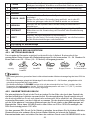
4.3 CONSOLE FEATURES
4.3.1 WEATHER FORECAST
The built-in barometer continually monitor atmosphere pressure. Based on the data collected,
it can predict the weather conditions in the forthcoming 12~24 hours within a 30~50km (19~31
miles) radius.
Sunny Partly cloudy Cloudy Rainy Rainy / Stormy Snowy
NOTE:
- The accuracy of a general pressure-based weather forecast is about 70% to 75%.
- The weather forecast is reecting the weather situation for next 12~24 hours, it may not necessarily
reect the current situation.
- The SNOWY weather forecast is not based on the atmospheric pressure, but based on the temperature
of outdoor. When the temperature is below -3°C (26°F), the SNOWY weather icon will be displayed on the
LCD.
4.3.2 BAROMETRIC PRESSURE
The atmospheric pressure is the pressure at any location of the earth caused by the weight
of the column of air above it. One atmospheric pressure refers to the average pressure
and gradually decreases as altitude increases. Meteorologists use barometers to measure
atmospheric pressure. Because absolute atmospheric pressure decreases with altitude,
meteorologist correct the pressure relative to sea-level conditions. Hence, your ABS pressure
may read 1000 hPa at altitude of 300m, but the REL pressure is 1013 hPa.
To obtain accurate REL pressure for your area, consult your local ocial observatory or check
weather website on internet for real time barometer conditions, and then adjust the relative
pressure in Calibration (section 5.6) of conguration app.
1. Rate of change graph for the barometric pressure
2. Pressure drop alert indicator
3. Average hourly pressure of 3, 6, 12, or 24 hours ago
4. Barometric pressure trend
5. Barometric pressure reading
1 2 3
5
4
4.3.2.1 VIEWING PRESSURE HISTORY
In normal mode, press [ BARO ] key to view the average hourly pressure of 3, 6, 12 and 24
hours ago.

16
4.3.2.2 ABSOLUTE OR RELATIVE BAROMETRIC PRESSURE MODE
In normal mode, press and hold [ BARO ] key with 2 second to switch between ABSOLUTE
and RELATIVE barometric pressure.
4.3.3 OUTDOOR TEMPERATURE, HUMIDITY
1. Outdoor temperature reading
2. Outdoor sensor low battery indicator
3. Outdoor sensor signal indicator to show the signal
receiving strength
4. Outdoor temperature high / low alert indicator
5. Outdoor temperature trend
6. Outdoor humidity high / low alert indicator
7. Outdoor humidity trend
8. Outdoor humidity reading
3 41 62 5 7 8
NOTE:
If temperature / humidity is below the measurement range, the reading will show “Lo”. If
temperature / humidity is above the measurement range, the reading will show “HI”.
4.3.4 OUTDOOR TEMPERATURE INDEX
Press [ INDEX ] key to switch between Feels Like, Heat
Index, Wind Chill, and Dew Point of outdoor.
4.3.4.1 FEELS LIKE
Feels Like Temperature shows what the outdoor temperature will feel like. It’s a collective
mixture of Wind Chill factor (18°C or below) and the Heat Index (26°C or above). For
temperatures in the region between 18.1°C to 25.9°C where both wind and humidity are less
signicant in aecting the temperature, the device will show the actual outdoor measured
temperature as Feels Like Temperature.
4.3.4.2 HEAT INDEX
The heat index which is determined by the wireless 5-in-1 sensor's temperature & humidity
data when the temperature is between 26°C (79°F) and 50°C (120°F).
Heat Index range Warning Explanation
27°C to 32°C (80°F to 90°F) Caution Possibility of heat exhaustion
33°C to 40°C (91°F to 105°F) Extreme Caution Possibility of heat dehydration
41°C to 54°C (106°F to 129°F) Danger Heat exhaustion likely
≥55°C (≥130°F) Extreme Danger Strong risk of dehydration / sun stroke

17
4.3.4.3 WIND CHILL
A combination of the wireless 5-in-1 sensor's temperature and wind speed data determines the
current wind chill factor. Wind chill number are always lower than the air temperature for wind
values where the formula applied is valid (i.e. due to limitation of formula, actual air temperature
higher than 10°C with wind speed below 9km/h may result in erroneous wind chill reading).
4.3.4.4 DEW POINT
- The dew point is the temperature below which the water vapor in air at constant barometric
pressure condenses into liquid water at the same rate at which it evaporates. The condensed
water is called dew when it forms on a solid surface.
- The dew point temperature is determined by the temperature & humidity data from wireless
5-in-1 sensor.
4.3.5 INDOOR TEMPERATURE & HUMIDITY
1. Indoor temperature reading
2. Indoor temperature high / low alert indicator
3. Indoor temperature trend
4. Indoor humidity high / low alert indicator
5. Indoor humidity trend
6. Indoor humidity reading
1 3 5 62 4
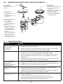
4.3.6 WIND
4.3.6.1 WIND SPEED AND DIRECTION SECTION OVERVIEW
1. High wind speed alert indicator
2. Gust indicator
3. Real time wind direction indicator (16 points)
4. Average / gust wind speed or Beaufort scale
4
3
1
2
4.3.6.2 WIND SPEED, GUST AND BEAUFORT SCALE DISPLAY
Press [WIND] key to switch display between Average wind speed, Gust, and Beaufort scale.
NOTE:
- Wind speed is dened as the average wind speed in the 12 second update period
- Gust is dened as the peak wind speed in the 12 second update period
4.3.6.3 BEAUFORT SCALE TABLE
The Beaufort scale is an international scale of wind velocities ranging from 0 (calm) to 12
(Hurricane force).
Beaufort Scale Description Wind Speed Land Condition
0 Calm
< 1 km/h
Calm. Smoke rises vertically.
< 1 mph
< 1 knots
< 0.3 m/s

18
1 Light air
1.1 ~ 5km/h Smoke drift indicates wind direction.
Leaves and wind vanes are stationary.
1 ~ 3 mph
1 ~ 3 knots
0.3 ~ 1.5 m/s
2 Light breeze
6 ~ 11 km/h
Wind felt on exposed skin. Leaves rustle.
Wind vanes begin to move.
4 ~ 7 mph
4 ~ 6 knots
1.6 ~ 3.3 m/s
3 Gentle breeze
12 ~ 19 km/h
Leaves and small twigs constantly moving,
light ags extended.
8 ~ 12 mph
7 ~ 10 knots
3.4 ~ 5.4 m/s
4Moderate
breeze
20 ~ 28 km/h Dust and loose paper raised. Small
branches begin to move.
13 ~ 17 mph
11 ~ 16 knots
5.5 ~ 7.9 m/s
5 Fresh breeze
29 ~ 38 km/h
Branches of a moderate size move.
Small trees in leaf begin to sway.
18 ~ 24 mph
17 ~ 21 knots
8.0 ~ 10.7 m/s
6 Strong breeze
39 ~ 49 km/h Large branches in motion. Whistling heard
in overhead wires. Umbrella use becomes
dicult. Empty plastic bins tip over.
25 ~ 30 mph
22 ~ 27 knots
10.8 ~ 13.8 m/s
7 High wind
50 ~ 61 km/h
Whole trees in motion. Eort needed to
walk against the wind.
31 ~ 38 mph
28 ~ 33 knots
13.9 ~ 17.1 m/s
8 Gale
62 ~ 74 km/h Some twigs broken from trees.
Cars veer on road. Progress on foot is
seriously impeded
39 ~ 46 mph
34 ~ 40 knots
17.2 ~ 20.7 m/s
9 Strong gale
75 ~ 88 km/h Some branches break o trees, and some
small trees blow over. Construction /
temporary signs and barricades blow over.
47 ~ 54 mph
41 ~ 47 knots
20.8 ~ 24.4 m/s
10 Storm
89 ~ 102 km/h
Trees are broken o or uprooted,
structural damage likely.
55 ~ 63 mph
48 ~ 55 knots
24.5 ~ 28.4 m/s
11 Violent storm
103 ~ 117 km/h
Widespread vegetation and structural
damage likely.
64 ~ 73 mph
56 ~ 63 knots
28.5 ~ 32.6 m/s
12 Hurricane force
≥ 118 km/h Severe widespread damage to vegetation
and structures. Debris and unsecured
objects are hurled about.
≥ 74 mph
≥ 64 knots
≥ 32.7m/s

19
4.3.7 RAIN
The RAIN section shows the rainfall or rain rate information.
1. Rain rate high alert indicator
2. Period of rainfall and rain rate
3. Reading of rainfall or rain rate 3
1
2
4.3.7.1 THE RAIN DISPLAY MODE
Press [ RAIN ] key to toggle between:
-DAY - the total rainfall from midnight (default)
-WEEK - the total rainfall of the current week
-MONTH- the total rainfall of the current calendar month
-TOTAL - the total rainfall since the last reset
-RATE - current rainfall rate (base on 10 min rain data)
-EVENT - rain event is dened as continuous rain, and resets to zero if rainfall accumulation
is less than 10 mm(0.039 in) in a 24 hour period
4.3.7.2 TO RESET THE TOTAL RAINFALL RECORD
In normal mode, press and hold [ RAIN ] key for 6 seconds to reset all the rainfall record.
NOTE:
Erroneous readings may occur during the installation of the 5-in-1 sensor array. Once the
installation is completed and functioning correctly, it’s advisable to clear all the data and start
afresh.
4.3.8 MAXIMUM / MINIMUM RECORDS
The console can record
MAX / MIN readings
since last reset and on
daily basic. MAX reading
since last reset MIN reading
since last reset Daily MAX
reading Daily MIN reading
4.3.8.1 DAILY AND SINCE MAX / MIN RECORDS
In normal mode, press [ MEMORY ] key to check the records of the on screen reading in the
following display sequence: since MAX records since MIN records daily MAX records
daily MIN records.
4.3.8.2 TO CLEAR THE MAX/MIN RECORDS
Press and hold [ MAX / MIN ] key for 2 seconds to reset all the MAX and MIN records.

20
4.3.9 MOON PHASE
The moon phase is determined by time
and date of the console. The following
table explains the moon phase icons of
the Northern and Southern Hemispheres.
Please refer to section 4.4.1 web
interface about how to setup for the
Southern Hemisphere.
Northern
Hemisphere Moon Phase Southern
Hemisphere
New Moon
Waxing Crescent
First quarter
Waxing Gibbous
Full Moon
Waning Gibbous
Third quarter
Waning
Crescent
4.3.10 WIRELESS SENSOR SIGNAL RECEIVING
1. The console display signal strength for the wireless sensor array, as per table below:
No signal Weak signal Good signal
5-in-1 wireless sensor array
2. If the signal has discontinued and does not recover within 15 minutes, the signal icon will
disappear. The temperature and humidity will display “Er” for the corresponding channel.
3. If the signal does not recover within 48 hours, the “Er” display will become permanent. You
need to replace the batteries and then press [ SENSOR / WI-FI ] key to pair up the sensor
again.
4.3.11 TIME SYNCHRONIZE STATUS
After the console has connected to the time server, it can
get the UTC time. The “ ” icon will appear on the
LCD.
The time will automatically synchronize per hour. You can also press the [ REFRESH ] key to
get the Internet time manually within 1 minute.
4.3.12 WI-FI CONNECTION STATUS
WI-FI icon on the console display indicates the console's connection status with WI-FI router.
Stable: Console is in
connection with WI-FI router Flashing: Console is trying
to connect to WI-FI router
Seite wird geladen ...
Seite wird geladen ...
Seite wird geladen ...
Seite wird geladen ...
Seite wird geladen ...
Seite wird geladen ...
Seite wird geladen ...
Seite wird geladen ...
Seite wird geladen ...
Seite wird geladen ...
Seite wird geladen ...
Seite wird geladen ...
Seite wird geladen ...
Seite wird geladen ...
Seite wird geladen ...
Seite wird geladen ...
Seite wird geladen ...
Seite wird geladen ...
Seite wird geladen ...
Seite wird geladen ...
Seite wird geladen ...
Seite wird geladen ...
Seite wird geladen ...
Seite wird geladen ...
Seite wird geladen ...
Seite wird geladen ...
Seite wird geladen ...
Seite wird geladen ...
Seite wird geladen ...
Seite wird geladen ...
Seite wird geladen ...
Seite wird geladen ...
Seite wird geladen ...
Seite wird geladen ...
Seite wird geladen ...
Seite wird geladen ...
Seite wird geladen ...
Seite wird geladen ...
Seite wird geladen ...
Seite wird geladen ...
Seite wird geladen ...
Seite wird geladen ...
Seite wird geladen ...
Seite wird geladen ...
Seite wird geladen ...
Seite wird geladen ...
Seite wird geladen ...
Seite wird geladen ...
Seite wird geladen ...
Seite wird geladen ...
Seite wird geladen ...
Seite wird geladen ...
Seite wird geladen ...
Seite wird geladen ...
Seite wird geladen ...
Seite wird geladen ...
-
 1
1
-
 2
2
-
 3
3
-
 4
4
-
 5
5
-
 6
6
-
 7
7
-
 8
8
-
 9
9
-
 10
10
-
 11
11
-
 12
12
-
 13
13
-
 14
14
-
 15
15
-
 16
16
-
 17
17
-
 18
18
-
 19
19
-
 20
20
-
 21
21
-
 22
22
-
 23
23
-
 24
24
-
 25
25
-
 26
26
-
 27
27
-
 28
28
-
 29
29
-
 30
30
-
 31
31
-
 32
32
-
 33
33
-
 34
34
-
 35
35
-
 36
36
-
 37
37
-
 38
38
-
 39
39
-
 40
40
-
 41
41
-
 42
42
-
 43
43
-
 44
44
-
 45
45
-
 46
46
-
 47
47
-
 48
48
-
 49
49
-
 50
50
-
 51
51
-
 52
52
-
 53
53
-
 54
54
-
 55
55
-
 56
56
-
 57
57
-
 58
58
-
 59
59
-
 60
60
-
 61
61
-
 62
62
-
 63
63
-
 64
64
-
 65
65
-
 66
66
-
 67
67
-
 68
68
-
 69
69
-
 70
70
-
 71
71
-
 72
72
-
 73
73
-
 74
74
-
 75
75
-
 76
76


Bresser 7003350 Bedienungsanleitung
- Kategorie
- Wetterstationen
- Typ
- Bedienungsanleitung
in anderen Sprachen
- English: Bresser 7003350 Owner's manual