Baumer TDP 0,2, TDPZ 0,2 Installation and Operating Instructions
- Typ
- Installation and Operating Instructions

TDP 0,2 (TDPZ 0,2)
Tachogenerator (Doppel-Tachogenerator)
EURO-Flansch B10
Tachogenerator (Twin tachogenerator)
EURO ange B10
Montage- und Betriebsanleitung
Mounting and operating instructions
MB079 - 11055688
Baumer_TDP02-TDPZ02_II_DE-EN (20A1)

Baumer_TDP02-TDPZ02_II_DE-EN (20A1)
MB079 - 11055688
Inhaltsverzeichnis
Inhaltsverzeichnis
1 Allgemeine Hinweise ................................................................................................................................................ 1
2 Sicherheitshinweise
.................................................................................................................................................3
3 Vorbereitung
..................................................................................................................................................................5
3.1 Lieferumfang
..................................................................................................................................................... 5
3.1.1 TDP (TDPZ) 0,2 LT - B10 ........................................................................................................................5
3.1.2 TDP (TDPZ) 0,2 LT - B10 mit Option B14: Zweites Wellenende ........................................ 6
3.1.3 TDP 0,2 LS - B10 ....................................................................................................................................... 7
3.2 Zur Montage erforderlich (nicht im Lieferumfang enthalten) ...................................................7
3.3 Erforderliches Werkzeug (nicht im Lieferumfang enthalten) ...................................................8
4 Montage .............................................................................................................................................................................8
4.1 Schritt 1
...............................................................................................................................................................8
4.2 Schritt 2 ...............................................................................................................................................................9
4.3 Schritt 3 ............................................................................................................................................................ 10
4.4 Schritt 4 ............................................................................................................................................................ 10
4.5 Maximal zulässige Montagefehler unter Verwendung der
Baumer Hübner Federscheibenkupplung K 35 ............................................................................11
4.6 Hinweis bei Verwendung einer Klauenkupplung (zum Beispiel „ROTEX®“) ............... 12
4.7 Schritt 5 - TDP (TDPZ) 0,2 LT mit Klemmenkasten und Druckschraube ...................... 13
4.8 Schritt 5 - TDP (TDPZ) 0,2 LT mit Klemmenkasten und Kabelverschraubung .......... 13
4.9 Schritt 5 - TDP 0,2 LS mit Kabelverschraubung ......................................................................... 14
4.10 Montagehinweis ........................................................................................................................................... 15
5 Abmessungen ............................................................................................................................................................ 16
5.1 TDP 0,2 LT - B10
......................................................................................................................................... 16
5.2 TDPZ 0,2 LT - B10 ...................................................................................................................................... 16
5.3 TDP 0,2 LT - B10/B14 .................................................................................................................................17
5.4 TDPZ 0,2 LT - B10/B14 ..............................................................................................................................17
5.5 TDP 0,2 LS - B10 ..........................................................................................................................................17
6 Elektrischer Anschluss ....................................................................................................................................... 18
6.1 TDP 0,2 LT
...................................................................................................................................................... 18
6.2 TDPZ 0,2 LT ................................................................................................................................................... 18
6.3 TDP 0,2 LS ..................................................................................................................................................... 18
7 Betrieb und Wartung ............................................................................................................................................. 19
7.1 Austausch der Kohlebürsten
................................................................................................................. 19
8 Demontage ................................................................................................................................................................... 20
8.1 Schritt 1 - TDP 0,2 (TDPZ) LT mit Klemmenkasten und Druckschraube
...................... 20
8.2 Schritt 1 - TDP (TDPZ) 0,2 LT mit Klemmenkasten und Kabelverschraubung .......... 20
8.3 Schritt 1 - TDP 0,2 LS mit Kabelverschraubung ......................................................................... 21
8.4 Schritt 2 ............................................................................................................................................................ 22
8.5 Schritt 3 ............................................................................................................................................................ 22
8.6 Schritt 4 ............................................................................................................................................................ 22
9 Technische Daten .................................................................................................................................................... 23
9.1 Technische Daten - elektrisch
.............................................................................................................. 23
9.2 Technische Daten - mechanisch ......................................................................................................... 23
9.3 Daten nach Typ ............................................................................................................................................. 24
9.4 Ersatzschaltbild ............................................................................................................................................ 24
10 Zubehör .......................................................................................................................................................................... 27

MB079 - 11055688
Baumer_TDP02-TDPZ02_II_DE-EN (20A1)
Table of contents
Table of contents
1 General notes ................................................................................................................................................................ 2
2 Security indications
.................................................................................................................................................. 4
3 Preparation
.....................................................................................................................................................................5
3.1 Scope of delivery
............................................................................................................................................ 5
3.1.1 TDP (TDPZ) 0,2 LT - B10 .......................................................................................................................5
3.1.2 TDP (TDPZ) 0,2 LT - B10 with option B14: Second shaft end ............................................6
3.1.3 TDP 0,2 LS - B10 ........................................................................................................................................7
3.2 Required for mounting (not included in scope of delivery) ....................................................... 7
3.3 Required tools (not included in scope of delivery) ........................................................................ 8
4 Mounting ........................................................................................................................................................................... 8
4.1 Step 1
...................................................................................................................................................................8
4.2 Step 2 ...................................................................................................................................................................9
4.3 Step 3 ................................................................................................................................................................ 10
4.4 Step 4 ................................................................................................................................................................ 10
4.5 Maximum permissible mounting tolerance when the
Baumer Hübner K 35 spring disk coupling is used .....................................................................11
4.6 Note when using a jaw-type coupling (for example “ROTEX®”) ........................................ 12
4.7 Step 5 - TDP (TDPZ) 0,2 LT with terminal box and pressure screw ................................ 13
4.8 Step 5 - TDP (TDPZ) 0,2 LT with terminal box and cable gland ........................................ 13
4.9 Step 5 - TDP 0,2 LS with cable gland ............................................................................................... 14
4.10 Mounting instruction .................................................................................................................................. 15
5 Dimensions .................................................................................................................................................................. 16
5.1 TDP 0,2 LT - B10
......................................................................................................................................... 16
5.2 TDPZ 0,2 LT - B10 ...................................................................................................................................... 16
5.3 TDP 0,2 LT - B10/B14 ............................................................................................................................... 17
5.4 TDPZ 0,2 LT - B10/B14 ............................................................................................................................ 17
5.5 TDP 0,2 LS - B10 ......................................................................................................................................... 17
6 Electrical connection ............................................................................................................................................ 18
6.1 TDP 0,2 LT
...................................................................................................................................................... 18
6.2 TDPZ 0,2 LT ................................................................................................................................................... 18
6.3 TDP 0,2 LS ..................................................................................................................................................... 18
7 Operation and maintenance ............................................................................................................................. 19
7.1 Replace of the carbon brushes
............................................................................................................ 19
8 Dismounting ................................................................................................................................................................ 20
8.1 Step 1 - TDP (TDPZ) 0,2 LT with terminal box and pressure screw
................................ 20
8.2 Step 1 - TDP (TDPZ) 0,2 LT with terminal box and cable gland ........................................ 20
8.3 Step 1 - TDP 0,2 LS with cable gland ............................................................................................... 21
8.4 Step 2 ................................................................................................................................................................ 22
8.5 Step 3 ................................................................................................................................................................ 22
8.6 Step 4 ................................................................................................................................................................ 22
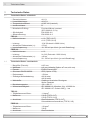
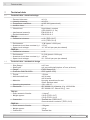
9 Technical data ............................................................................................................................................................ 25
9.1 Technical data - electrical ratings
....................................................................................................... 25
9.2 Technical data - mechanical design .................................................................................................. 25
9.3 Type data ......................................................................................................................................................... 26
9.4 Replacement switching diagram ......................................................................................................... 26
10 Accessories ................................................................................................................................................................. 27

1
Baumer_TDP02-TDPZ02_II_DE-EN (20A1)
MB079 - 11055688
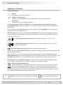
1 Allgemeine Hinweise
1 Allgemeine Hinweise
1.1 Zeichenerklärung:
Gefahr
Warnung bei möglichen Gefahren
Hinweis zur Beachtung
Hinweis zur Gewährleistung eines einwandfreien Betriebes des Gerätes
i
Information
Empfehlung für die Gerätehandhabung
1.2 Der Tachogenerator TDP 0,2 (TDPZ 0,2) ist ein generatorisch arbeitendes Prä zi sions-
Drehzahlmessgerät, das mit Sorgfalt nur von technisch qualiziertem Per sonal gehandhabt
werden darf.
1.3 Die zu erwartende Lebensdauer des Gerätes hängt von den Kugellagern ab, die mit einer
Dauerschmierung ausgestattet sind.
1.4 Kohlebürsten haben eine zu erwartende Lebensdauer, die vom Stromdurchgang abhängt
und in der Regel der Kugellagerlebensdauer entspricht. Ein Wechsel der Kohlebürsten ist nur
vorsorglich erforderlich.
1.5
Der Lagertemperaturbereich des Gerätes liegt zwischen -15 °C bis +70 °C.
1.6
Der Betriebstemperaturbereich des Gerätes liegt zwischen -30 °C bis +130 °C,
am Gehäuse gemessen.
1.7
EU-Konformitätserklärung gemäß den europäischen Richtlinien.
1.8 Wir gewähren 2 Jahre Gewährleistung im Rahmen der Bedingungen des Zentralverbandes der
Elektroindustrie (ZVEI).
1.9 Das Gerät darf nur wie in dieser Anleitung beschrieben geöffnet werden. Reparaturen oder
Wartungsarbeiten, die ein vollständiges Öffnen des Gerätes erfordern, sind ausschließlich vom
Hersteller durchzuführen. Am Gerät dürfen keine Veränderungen vorgenommen werden.
1.10 Bei Rückfragen bzw. Nachlieferungen sind die auf dem Typenschild des Gerätes angege-
benen Daten, insbesondere Typ und Seriennummer, unbedingt anzugeben.
1.11
Entsorgung (Umweltschutz):
Gebrauchte Elektro- und Elektronikgeräte dürfen nicht im Hausmüll entsorgt werden.
Das Produkt enthält wertvolle Rohstoffe, die recycelt werden können. Wenn immer
möglich sollen Altgeräte lokal am entsprechenden Sammeldepot entsorgt werden. Im
Bedarfsfall gibt Baumer den Kunden die Möglichkeit, Baumer-Produkte fachgerecht zu entsor-
gen. Weitere Informationen siehe www.baumer.com.
i
Achtung!
Beschädigung des auf dem Gerät bendlichen Siegels führt zu Gewährleistungsver-
lust.

MB079 - 11055688
Baumer_TDP02-TDPZ02_II_DE-EN (20A1)
2
General notes 1
1 General notes
1.1 Symbol guide:
Danger
Warnings of possible danger
General information for attention
Informations to ensure correct device operation
i
Information
Recommendation for device handling
1.2 The tachogenerator TDP 0,2 (TDPZ 0,2) is a generator-based working precision rotary
measurement device which must be handled with care by skilled personnel only.
1.3 The expected service life of the device depends on the ball bearings, which are equipped with
a permanent lubrication.
1.4 The expected service life of carbon brushes depends on the electrical current and is usually
consistent with the service life of the ball bearings. Replacement of the carbon brushes is only a
recommended precaution.
1.5
The storage temperature range of the device is between -15 °C and +70 °C.
1.6
The operating temperature range of the device is between -30 °C and +130 °C,
measured at the housing.
1.7
EU Declaration of Conformity meeting to the European Directives.
1.8 We grant a 2-year warranty in accordance with the regulations of the ZVEI (Central Association
of the German Electrical Industry).
1.9 The device may be only opened as described in this instruction. Repair or maintenance work
that requires opening the device completely must be carried out by the manufacturer. Altera-
tions of the device are not permitted.
1.10 In the event of queries or subsequent deliveries, the data on the device type label must be
quoted, especially the type designation and the serial number.
1.11
Disposal (environmental protection):
Do not dispose of electrical and electronic equipment in household waste. The product
contains valuable raw materials for recycling. Whenever possible, waste electrical and
electronic equipment should be disposed locally at the authorized collection point. If
necessary, Baumer gives customers the opportunity to dispose of Baumer products profession-
ally. For further information see www.baumer.com.
i
Warning!
Damaging the seal on the device invalidates warranty.

3
Baumer_TDP02-TDPZ02_II_DE-EN (20A1)
MB079 - 11055688
2 Sicherheitshinweise
2 Sicherheitshinweise
2.1 Verletzungsgefahr durch rotierende Wellen
Haare und Kleidungsstücke können von rotierenden Wellen erfasst werden.
• Vor allen Arbeiten alle Betriebsspannungen ausschalten und Maschinen stillsetzen.
2.2 Zerstörungsgefahr durch mechanische Überlastung
Eine starre Befestigung kann zu Überlastung durch Zwangskräfte führen.
• Die Beweglichkeit des Gerätes niemals einschränken.
Unbedingt die Montagehinweise beachten.
• Die vorgegebenen Abstände und/oder Winkel unbedingt einhalten.
2.3 Zerstörungsgefahr durch mechanischen Schock
Starke Erschütterungen, z. B. Hammerschläge, können zur Zerstörung des Gerätes führen.
• Niemals Gewalt anwenden.
Bei sachgemäßer Montage lässt sich alles leichtgängig zusammenfügen.
• Für die Demontage geeignetes Abziehwerkzeug benutzen.
2.4 Zerstörungsgefahr durch Verschmutzung
Schmutz kann im Gerät zu dessen Beschädigung führen.
• Während aller Arbeiten am Gerät auf absolute Sauberkeit achten.
• Niemals Öl oder Fett in das Innere des Gerätes gelangen lassen.
2.5 Zerstörungsgefahr durch klebende Flüssigkeiten
Klebende Flüssigkeiten können die Magnete und Kohlebürsten beschädigen. Die Demontage
eines mit der Achse verklebten Gerätes kann zu dessen Zerstörung führen.
2.6 Explosionsgefahr
Das Gerät nicht in Bereichen mit explosionsgefährdeten bzw. leicht entzündlichen Materialien
verwenden. Durch eventuelle Funkenbildung können diese leicht Feuer fangen und/oder explo-
dieren.

MB079 - 11055688
Baumer_TDP02-TDPZ02_II_DE-EN (20A1)
4
Security indications 2
2 Security indications
2.1 Risk of injury due to rotating shafts
Hair and clothes may become tangled in rotating shafts.
• Before all work switch off all voltage supplies and ensure machinery is stationary.
2.2 Risk of destruction due to mechanical overload
Rigid mounting may give rise to constraining forces.
• Never restrict the freedom of movement of the device.
The mounting instructions must be followed.
• It is essential that the specied clearances and/or angles are observed.
2.3 Risk of destruction due to mechanical shock
Violent shocks, e. g. due to hammer impacts, can lead to the destruction of the device.
• Never use force.
Mounting is simple when correct procedure is followed.
• Use suitable puller for dismounting.
2.4 Risk of destruction due to contamination
Dirt penetrating inside the device can damage the device.
• Absolute cleanliness must be maintained when carrying out any work on the device.
• Never allow lubricants to penetrate the device.
2.5 Risk of destruction due to adhesive uids
Adhesive uids can damage the magnets and the carbon brushes. Dismounting a device, se-
cured to a shaft by adhesive may lead to the destruction of the device.
2.6 Explosion risk
Do not use the device in areas with explosive and/or highly inammable materials.
They may explode and/or catch re by possible spark formation.

5
Baumer_TDP02-TDPZ02_II_DE-EN (20A1)
MB079 - 11055688
3 Vorbereitung
3.1 Lieferumfang
3.1.1 TDP (TDPZ) 0,2 LT - B10
3 Preparation
3.1 Scope of delivery
3.1.1 TDP (TDPZ) 0,2 LT - B10
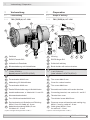
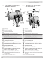
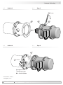
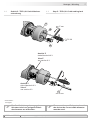
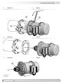
3 Vorbereitung / Preparation
1
Gehäuse
2
EURO-Flansch B10
3
Vollwelle mit Passfeder
4
Bürstenhalterung mit Kohlebürsten
4.1
Kohlebürsten, auch als Zubehör erhältlich,
1 Satz (2 Stück):
Bestellnummer 11076778 (S7/H7)
5
Abdeckhaube
6
Torxschraube M4x12 mm
7
Abdeckung für Kohlebürsten
8
1)
Torxschraube M4x6 mm
9
1)
Zweite Bürstenhalterung mit Kohlebürsten
10
Anschlussklemmen, s. Abschnitt 6.1 und 6.2.
11
Klemmenkastendeckel
12
Torx-/Schlitzschraube M4x32 mm
13
Druckschraube mit Scheibe und Dichtring
M16x1,5 mm für Kabel ø6...8 mm
14
Kabelverschraubung M20x1,5 mm
für Kabel ø5...13 mm
1)
Option Z: Doppel-Tachogenerator TDPZ 0,2
1
Housing
2
EURO ange B10
3
Solid shaft with key
4
Brush holder with carbon brushes
4.1
Carbon brushes, also available as accessory,
1 set (2 pieces):
Order number 11076778 (S7/H7)
5
Cover
6
Torx screw M4x12 mm
7
Cover for carbon brushes
8
1)
Torx screw M4x6 mm
9
1)
Second brush holder with carbon brushes
10
Connecting terminal, see section 6.1 and 6.2.
11
Terminal box cover
12
Torx/slotted screw M4x32 mm
13
Pressure screw with washer and sealing ring
M16x1,5 mm for cable ø6...8 mm
14
Cable gland M20x1,5 mm
for cable ø5...13 mm
1)
Option Z: Twin tachogenerator TDPZ 0,2
1
78
5
6
7
8
2
3
4
9
10
11
12
13
14
1)
1)
1) 1) 1)
4.1

MB079 - 11055688
Baumer_TDP02-TDPZ02_II_DE-EN (20A1)
6
Vorbereitung / Preparation 3
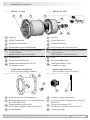
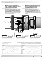
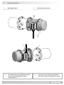
3.1.2 TDP (TDPZ) 0,2 LT - B10 mit Option
B14: Zweites Wellenende
3.1.2 TDP (TDPZ) 0,2 LT - B10 with option
B14: Second shaft end
1
Gehäuse
2
EURO-Flansch B10
3
Vollwelle mit Passfeder
4
Bürstenhalterung mit Kohlebürsten
4.1
Kohlebürsten, auch als Zubehör erhältlich,
1 Satz (2 Stück):
Bestellnummer 11076778 (S7/H7)
7
Abdeckung für Kohlebürsten
8
1)
Torxschraube M4x6 mm
9
1)
Zweite Bürstenhalterung mit Kohlebürsten
10
Anschlussklemmen, s. Abschnitt 6.1 und 6.2.
11
Klemmenkastendeckel
12
Torx-/Schlitzschraube M4x32 mm
13
Druckschraube mit Scheibe und Dichtring
M16x1,5 mm für Kabel ø6...8 mm
15
Linsenschraube M4x8 mm, ISO 7047
16
Option B14: Zweites Wellenende ø10 mm,
15,5 mm lang
1)
Option Z: Doppel-Tachogenerator TDPZ 0,2
1
Housing
2
EURO ange B10
3
Solid shaft with key
4
Brush holder with carbon brushes
4.1
Carbon brushes, also available as accessory,
1 set (2 pieces):
Order number 11076778 (S7/H7)
7
Cover for carbon brushes
8
1)
Torx screw M4x6 mm
9
1)
Second brush holder with carbon brushes
10
Connecting terminal, see section 6.1 and 6.2.
11
Terminal box cover
12
Torx/slotted screw M4x32 mm
13
Pressure screw with washer and sealing ring
M16x1,5 mm for cable ø6...8 mm
15
Pan head screw M4x8 mm, ISO 7047
16
Option B14: Second shaft end ø10 mm, length
15.5 mm
1)
Option Z: Twin tachogenerator TDPZ 0,2
1
7
8
7 15
16
7
8
2
3
9
10
11
12
13
1)
1)
1)
1)
1)
4.1
4

7
Baumer_TDP02-TDPZ02_II_DE-EN (20A1)
MB079 - 11055688
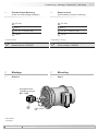
3 Vorbereitung / Preparation
1
Gehäuse
2
EURO-Flansch B10
3
Vollwelle mit Passfeder
4
Bürstenhalterung mit Kohlebürsten
4.1
Kohlebürsten, auch als Zubehör erhältlich,
1 Satz (2 Stück):
Bestellnummer 11076778 (S7/H7)
17
Abdeckhaube
18
Torxschraube M4x14 mm
19
Kabelverschraubung M16x1,5 mm
für Kabel ø5...9 mm
1
Housing
2
EURO ange B10
3
Solid shaft with key
4
Brush holder with carbon brushes
4.1
Carbon brushes, also available as accessory,
1 set (2 pieces):
Order number 11076778 (S7/H7)
17
Cover
18
Torx screw M4x14 mm
19
Cable gland M16x1,5 mm
for cable ø5...9 mm
1
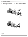
3.1.3 TDP 0,2 LS - B10 3.1.3 TDP 0,2 LS - B10
23
17
18 19
3.2 Zur Montage erforderlich
(nicht im Lieferumfang enthalten)
3.2 Required for mounting
(not included in scope of delivery)
20
Anbauvorrichtung, kundenspezisch
21
Befestigungsschrauben für Anbauvorrichtung
ISO 4017, M6x16 mm
22
Federscheibenkupplung K 35,
als Zubehör erhältlich, siehe Abschnitt 4.5.
23
Anschlusskabel
20
Installation tting, customized
21
Fixing screws for installation tting ISO 4017,
M6x16 mm
22
Spring disk coupling K 35,
available as accessory, see section 4.5.
23
Connecting cable
20
21
22 23
4.1
4
12x

MB079 - 11055688
Baumer_TDP02-TDPZ02_II_DE-EN (20A1)
8
Vorbereitung - Montage / Preparation - Mounting 3-4
3.3 Erforderliches Werkzeug
(nicht im Lieferumfang enthalten)
3.3 Required tools
(not included in scope of delivery)
Anzugsmoment:
Tightening torque:
M
t
= 1 Nm
4 Montage
4.1 Schritt 1
4 Mounting
4.1 Step 1
22
*
* Siehe Seite 7
See page 7
2,5 mm
PH 1
2)
10, 16, 17 und 22 mm
2)
TX 20
2)
Je nach Version
24
Werkzeugset als Zubehör erhältlich:
Bestellnummer 11068265
2.5 mm
PH 1
2)
10, 16, 17 and 22 mm
2)
TX 20
2)
Depending on version
24
Tool kit available as accessory:
Order number 11068265
2.5 mm

9
Baumer_TDP02-TDPZ02_II_DE-EN (20A1)
MB079 - 11055688
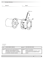
4 Montage / Mounting
4.2 Schritt 2 4.2 Step 2
Antriebswelle einfetten. Lubricate drive shaft.
20
*
21
*
* Siehe Seite 7
See page 7
Die Antriebswelle sollte einen
möglichst kleinen Rundlauffehler
aufweisen. Rundlauffehler verursa-
chen Vibrationen, die die Lebensdauer
des Gerätes verkürzen können.
The drive shaft should have as less
runout as possible.
Runouts can cause vibrations, which
can shorten the service life of the
device.
10 mm

MB079 - 11055688
Baumer_TDP02-TDPZ02_II_DE-EN (20A1)
10
Montage / Mounting 4
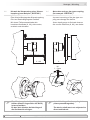
4.3 Schritt 3 4.3 Step 3
4.4 Schritt 4 4.4 Step 4
Anzugsmoment:
Tightening torque:
M
t
= 1.3 ±10 % Nm
20 21
* *
2
*
22
*
* Siehe Seite 5, 6 oder 7
See page 5, 6 or 7
10 mm
2.5 mm

11
Baumer_TDP02-TDPZ02_II_DE-EN (20A1)
MB079 - 11055688
4 Montage / Mounting
F
max
= 10N
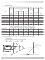
4.5 Maximal zulässige Montagefehler
unter Verwendung der Baumer Hübner
Federscheibenkupplung K 35
Geräte mit Vollwelle sollten unter Verwen-
dung der Baumer Hübner Federschei-
benkupplung K35 (Zubehör) angetrieben
werden, die sich ohne axialen Druck auf
die Welle schieben lässt.
4.5 Maximum permissible mounting toler-
ance when the Baumer Hübner K 35
spring disk coupling is used
Devices with a solid shaft should be
driven through the Baumer Hübner K35
spring disk coupling (accessory), that
can be pushed onto the shaft without axial
loading.
Zulässiger Parallelversatz
Admissible parallel misalignment
Zulässiger Winkelfehler
Admissible angular error
Zulässige Axialbewegung
Admissible axial movement
±0.2 (±0.05*)
±1°
* Mit isolierender Kunststoffnabe
With insulated hub
±0.7 (±0.3*)
Die Montage an den Antrieb muss mit
möglichst geringem Winkelfehler und
Parallelversatz erfolgen.
Das harte Aufschlagen von Kupp-
lungsteilen auf die Welle ist wegen der
Gefahr von Kugellagerbeschädi-
gungen nicht zulässig.
The device must be mounted on the
drive with the least possible angular
error and parallel misalignment.
Coupling components must not be
driven onto the shaft with improper
force (e. g. hammer impacts), because
of the risk of damaging the ball
bearings.
Alle Abmessungen in Millimeter (wenn nicht anders angegeben)
All dimensions in millimeters (unless otherwise stated)

MB079 - 11055688
Baumer_TDP02-TDPZ02_II_DE-EN (20A1)
12
Montage / Mounting 4
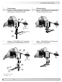
4.6 Hinweis bei Verwendung einer Klauen-
kupplung (zum Beispiel „ROTEX®“)
Eine falsche Montage der Klauenkupplung
führt zur Beschädigung des Gerätes.
Mit einem Tiefenmessschieber die
korrekten Abstände (L, L1), siehe unten,
ermitteln und einhalten.
4.6 Note when using a jaw-type coupling
(for example “ROTEX®”)
Incorrect mounting of the jaw-type cou-
pling can damage the device.
Use a depth gauge to nd and observe
the correct distances (L, L1), see below.
Eine Blockung der beiden Kupplungs-
hälften (Klauen liegen Stirn auf Stirn)
ist zu vermeiden.
Es darf kein direkter Axialschlag auf
die Gerätewelle erfolgen.
Avoid blocking of both coupling halves
(claws pressed together).
The device shaft must not subjected to
direct axial shock.
L + L1 L
L1
1...2 mm

13
Baumer_TDP02-TDPZ02_II_DE-EN (20A1)
MB079 - 11055688
4 Montage / Mounting
Ansicht W bzw. X
siehe Abschnitt 6.1 bzw. 6.2.
View W or X
see section 6.1 or 6.2.
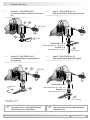
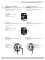
4.7 Schritt 5 - TDP (TDPZ) 0,2 LT
mit Klemmenkasten und Druckschrau-
be
4.7 Step 5 - TDP (TDPZ) 0,2 LT
with terminal box and pressure screw
4.8 Schritt 5 - TDP (TDPZ) 0,2 LT
mit Klemmenkasten und Kabelver-
schraubung
4.8 Step 5 - TDP (TDPZ) 0,2 LT
with terminal box and cable gland
Ansicht W bzw. X
siehe Abschnitt 6.1 bzw. 6.2.
View W or X
see section 6.1 or 6.2.
Zur Gewährleistung der angegebenen
Schutzart sind nur geeignete Kabel-
durchmesser zu verwenden.
To ensure the specied protection of
the device the correct cable diameter
must be used.
1211
**
13
*
1211
14
**
*
23
*
23
*
* Siehe Seite 5, 6 oder 7
See page 5, 6 or 7
ø6...8 mm
ø5...13 mm
TX 20
TX 20
16 mm
22 mm

MB079 - 11055688
Baumer_TDP02-TDPZ02_II_DE-EN (20A1)
14
Montage / Mounting 4
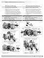
4.9 Schritt 5 - TDP 0,2 LS mit Kabelver-
schraubung
4.9 Step 5 - TDP 0,2 LS with cable gland
Ansicht Z
siehe Abschnitt 6.3.
View Z
see section 6.3.
Ansicht Y
siehe Abschnitt 6.3.
View Y
see section 6.3.
Zur Gewährleistung der angegebenen
Schutzart sind nur geeignete Kabel-
durchmesser zu verwenden.
To ensure the specied protection of
the device the correct cable diameter
must be used.
17
18
19
*
*
*
23
*
* Siehe Seite 7
See page 7
ø5...9 mm
17 mm
TX 20

15
Baumer_TDP02-TDPZ02_II_DE-EN (20A1)
MB079 - 11055688
4 Montage / Mounting
4.10 Montagehinweis 4.10 Mounting instruction
i
Wir empfehlen, das Gerät so zu
montieren, dass der Kabelanschluss
keinem direkten Wassereintritt
ausgesetzt ist.
i
It is recommended to mount the device
with cable connection facing down-
ward and being not exposed to water.

MB079 - 11055688
Baumer_TDP02-TDPZ02_II_DE-EN (20A1)
16
Abmessungen / Dimensions 5
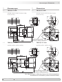
5 Abmessungen
5.1 TDP 0,2 LT - B10
(61100, 61101, 61102, 61104, 61109,
61110, 61121)
5 Dimensions
5.1 TDP 0,2 LT - B10
(61100, 61101, 61102, 61104, 6110 9,
61110, 61121)
5.2 TDPZ 0,2 LT - B10
(61550, 61551, 61552, 61553)
5.2 TDPZ 0,2 LT - B10
(61550, 61551, 61552, 61553)
A B
ø7
k6
8.3 3
ø11
k6
12.6 4
ø14
k6
16.1 5
A B
ø7
k6
8.3 3
ø11
k6
12.6 4
ø14
k6
16.1 5
Drehrichtung positiv
Positive rotating direction
Drehrichtung positiv
Positive rotating direction
Alle Abmessungen in Millimeter (wenn nicht anders angegeben)
All dimensions in millimeters (unless otherwise stated)

17
Baumer_TDP02-TDPZ02_II_DE-EN (20A1)
MB079 - 11055688
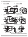
5 Abmessungen / Dimensions
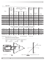
5.5 TDP 0,2 LS - B10
(62256)
5.5 TDP 0,2 LS - B10
(62256)
5.3 TDP 0,2 LT - B10/B14
(61301, 61302, 61303)
5.3 TDP 0,2 LT - B10/B14
(61301, 61302, 61303)
Drehrichtung positiv
Positive rotating direction
Drehrichtung positiv
Positive rotating direction
A B
ø11
k6
12.6 4
ø14
k6
16.1 5
5.4 TDPZ 0,2 LT - B10/B14
(61801)
5.4 TDPZ 0,2 LT - B10/B14
(61801)
Drehrichtung positiv
Positive rotating direction
Alle Abmessungen in Millimeter (wenn nicht anders angegeben)
All dimensions in millimeters (unless otherwise stated)
Seite wird geladen ...
Seite wird geladen ...
Seite wird geladen ...
Seite wird geladen ...
Seite wird geladen ...
Seite wird geladen ...
Seite wird geladen ...
Seite wird geladen ...
Seite wird geladen ...
Seite wird geladen ...
Seite wird geladen ...
Seite wird geladen ...
-
 1
1
-
 2
2
-
 3
3
-
 4
4
-
 5
5
-
 6
6
-
 7
7
-
 8
8
-
 9
9
-
 10
10
-
 11
11
-
 12
12
-
 13
13
-
 14
14
-
 15
15
-
 16
16
-
 17
17
-
 18
18
-
 19
19
-
 20
20
-
 21
21
-
 22
22
-
 23
23
-
 24
24
-
 25
25
-
 26
26
-
 27
27
-
 28
28
-
 29
29
-
 30
30
-
 31
31
-
 32
32


Baumer TDP 0,2, TDPZ 0,2 Installation and Operating Instructions
- Typ
- Installation and Operating Instructions
Verwandte Artikel
-
Baumer FS 90 Installation and Operating Instructions
-
-
-
Baumer TDP 13, TDPZ 13 Datenblatt
-
-
Baumer TDP 0,2 + FSL, TDPZ 0,2 + FSL Installation and Operating Instructions
-
-
-
-