
Read This First
Bitte zuerst lesen
À lire avant de commencer
Leggere prima di iniziare
Leer antes de empezar
Lees dit eerst
Les dette først
Leia isto primeiro
Lue tämä ensin
Läs detta först
Informacje wstępne
入门
請先閱讀本手冊
먼저 읽을 내용
treated correctly and help to reduce potential impacts on the
environment and human health, which could otherwise result
from inappropriate handling. Recycling of products helps to
conserve natural resources and protect the environment.
For more detailed information on collection and recycling
systems for this product, please contact the shop where
you purchased it, your local dealer or sales/service
representatives.
All Other Users
If you wish to discard this product, please contact your local
authorities, the shop where you bought this product, your
local dealer or sales/service representatives.
For Turkey only
Note for the Battery and/or Accumulator Symbol
In accordance with the Battery Directive 2006/66/
EC Article 20 Information for end-users Annex
II, the above symbol is printed on batteries and
accumulators.
This symbol means that in the European Union, used
batteries and accumulators should be disposed of
separately from your household waste.
In the EU, there are separate collection systems for not only
used electrical and electronic products but also batteries
and accumulators.
Please dispose of them correctly at your local community
waste collection/recycling centre.
Notes to users in the United States of America
FCC Rules
Note :
This equipment has been tested and found to comply with
the limits for a Class A digital device, pursuant to Part 15
of the FCC Rules. These limits are designed to provide
reasonable protection against harmful interference when the
equipment is operated in a commercial environment. This
equipment generates, uses and can radiate radio frequency
energy and , if not installed and used in accordance with
the instruction manual, may cause harmful interference
to radio communications. Operation of this equipment in
a residential area is likely to cause harmful interference
in which case the user will be required to correct the
interference at his own expense.
Caution :
Changes or modifications not expressly approved by the
party responsible for compliance could void the user’s
authority to operate the equipment.
Supplier’s Declaration of Conformity
This device complies with Part 15 of the FCC Rules.
Operation is subject to the following two conditions:
(1) This device may not cause harmful interference, and
(2) This device must accept any interference received,
including interference that may cause undesired operation.
Responsible party: Ricoh USA, Inc.
Address: 300 Eagleview Boulevard, Suite 200 Exton,
PA 19341, U.S.A.
Telephone number: +1 610-296-8000
Product Name: Collaboration Board Controller Type 3
Model Number: Y440
This product is used with RICOH Collaboration
Board only. It cannot be used with other
products. For more details about the product
and safety information, see the manual of the
main unit.
Laws and Regulations
Warning on Class A Product
Warning:
This equipment is compliant with Class A of CISPR 32. In
a residential environment this equipment may cause radio
interference.
Operation of this equipment in a residential environment
could cause radio interference.
As this machine is not a household appliance, it does not con-
form to ErP Directive 2009/125/EC which was revised in 2013.
CE Marking Traceability Information (For EU
Countries Only)
Manufacturer:
Ricoh Co., Ltd.
3-6 Nakamagome 1-chome, Ohta-ku, Tokyo. 143-8555, Japan
Importer:
Ricoh Europe SCM B.V.
Blankenweg 24, 4612 RC Bergen op Zoom, The Netherlands
User Information for Wireless Network (For EU
Countries Only)
Declaration of Conformity
Notice to Users in EEA Countries
This product complies with the essential Require-
ments and provisions of Directive 2014/53/EU.
The CE Declaration of Conformity is available by accessing
the URL:
http://www.ricoh.com/products/ce_doc2/
and selecting the product applicable.
Outdoor use of the 5.150-5.350GHz band is prohibited.
Operating frequency band: 2400 - 2483.5 MHz
maximum radio-frequency power: less than 20.0 dBm
Operating frequency band: 5150 - 5350 MHz(W52, W53) /
5470 - 5725 MHz(W56)
maximum radio-frequency power(e.i.r.p): less than 20.0
dBm / 27.0 dBm (without TPC)
*TPC:Transmit Power Control
As this equipment with the radiating part is not intended to
be used in close proximity to the human body, it is recom-
mended to use at least 20 cm apart from the user.
User Information on Electrical and Electronic
Equipment
Users in the countries where this symbol shown in this
section has been specied in national law on collection
and treatment of E-waste
Our Products contain high quality components and are
designed to facilitate recycling.
Our products or product packaging are marked with the
symbol below.
The symbol indicates that the product must
not be treated as municipal waste. It must be
disposed of separately via the appropriate return
and collection systems available. By following
these instructions you ensure that this product is
This transmitter must not be co-located or operated in
conjunction with any other antenna or transmitter.
5. l 5-5.25GHz band is restricted to indoor operations only.
Compliance with FCC requirement 15.407(c) Data
transmission is always initiated by software, which is the
passed down through the MAC, through the digital and analog
baseband, and finally to the RF chip.
Several special packets are initiated by the MAC.
These are the only ways the digital baseband portion will turn
on the RF transmitter, which it then turns off at the end of the
packet.
Therefore, the transmitter will be on only while one of the
aforementioned packets is being transmitted.
In other words, this device automatically discontinue
transmission in case of either absence of information to
transmit or operational failure.
Frequency Tolerance: ±20 ppm
This device complies with part 15 of the FCC Rules.
Operation is subject to the following two conditions:
(1) This device may not cause harmful interference, and
(2) this device must accept any interference received,
including interference that may cause undesired operation.
This equipment complies with FCC radiation exposure limits
set forth for an uncontrolled environment and meets the FCC
radio frequency (RF) Exposure Guidelines. This equipment
should be installed and operated keeping the radiator at
least 20 cm or more away from person’s body (excluding
extremities: hands, wrists, feet and ankles).
Notes to Users in the State of California (Notes to Users
in USA)
Perchlorate Material - special handling may apply.
See: www.dtsc.ca.gov/hazardouswaste/perchlorate
Notes to Canadian Users of ICES -003 Conformance
CAN ICES-3 (A) / NMB-3 (A)
Notes to Canadian Users of Wireless Devices
This device contains licence-exempt transmitter(s)/
receiver(s) that comply with Innovation, Science and
Economic Development Canada’s licence-exempt RSS(s).
Operation is subject to the following two conditions:
(1) This device may not cause interference.
(2) This device must accept any interference, including
interference that may cause undesired operation of the
device.
L’émetteur/récepteur exempt de licence contenu dans
le présent appareil est conforme aux CNR d’Innovation,
Sciences et Développement économique Canada
applicables aux appareils radio exempts de licence.
L’exploitation est autorisée aux deux conditions suivantes :
(1) L’appareil ne doit pas produire de brouillage;
(2) L’appareil doit accepter tout brouillage radioélectrique
subi, même si le brouillage est susceptible d’en
compromettre le fonctionnement.
This equipment complies with IC radiation exposure limits
set forth for an uncontrolled environment and meets RSS-
102 of the IC radio frequency (RF) Exposure rules. This
equipment should be installed and operated keeping the
radiator at least 20cm or more away from person’s body
(excluding extremities: hands, wrists, feet and ankles).
Cet équipement est conforme aux limites d’exposition
aux rayonnements énoncées pour un environnement non
contrôlé et respecte les règles d’exposition aux fréquences
radioélectriques (RF) CNR-102 de l’IC. Cet équipement doit
être installé et utilisé en gardant une distance de 20 cm ou
plus entre le dispositif rayonnant et le corps (à l’exception
des extrémités : mains, poignets, pieds et chevilles).
Compliance with ISED requirement RSS-247 6.4 a) Data
transmission is always initiated by software, which is the
passed down through the MAC, through the digital and
analog baseband, and finally to the RF chip. Several
special packets are initiated by the MAC. These are the
only ways the digital baseband portion will turn on the RF
transmitter, which it then turns off at the end of the packet.
Therefore, the transmitter will be on only while one of the
aforementioned packets is being transmitted. In other
words, this device automatically discontinues transmission
in case of either absence of information to transmit or
operational failure.
Conformité à la norme CNR-247 6.4 a) La transmission
des données est toujours initiée par le logiciel, puis les
données sont transmises par l’intermédiaire du MAC, par la
bande de base numérique et analogique et, enfin, à la puce
RF. Plusieurs paquets spéciaux sont initiés par le MAC.
Ce sont les seuls moyens pour qu’une partie de la bande
de base numérique active l’émetteur RF, puis désactive
celui-ci à la fin du paquet. En conséquence, l’émetteur reste
uniquement activé lors de la transmission d’un des paquets
susmentionnés. En d’autres termes, ce dispositif interrompt
automatiquement toute transmission en cas d’absence
d’information à transmettre ou de défaillance.
5150-5250 MHz band is restricted to indoor operation only.
La bande 5150-5250 MHz est restreinte à une utilisation à
l’intérieur seulement.
5250-5350 MHz band is restricted to indoor operation only.
La bande 5250-5350 MHz est restreinte à une utilisation à
l’intérieur seulement.
This radio transmitter IC Number : 6158A-258ACNBT has
been approved by Industry Canada to operate with the
antenna types listed below with the maximum permissible
gain and required antenna impedance for each antenna
type indicated. Antenna types not included in this list, having
a gain greater that the maximaum gain indicated for that
type, are strictly prohibited for use with this device.
Antenna Model: WSS003
Antenna type: Dipole
Gain: 2dBi (2.4GHz, 5GHz)
worst-case tilt angle(s): 90°
Le présent émetteur radio IC Number : 6158A-258ACNBT
a été approuvé par Industrie Canada pour fonctionner avec
les types d’antenne énumérés ci-dessous et ayant un gain
admissible maximal et l’impédance requise pour chaque
type d’antenne. Les types d’antenne non inclus dans cette
liste, ou dont le gain est supérieur au gain maximal indiqué,
sont strictement interdits pour l’exploitation de l’émetteur.
Modèle d’antenne: WSS003
Type d’antenne: dipole
Gain: 2 dBi (2,4 GHz, 5 GHz)
angle(s) d’inclinaison le plus défavorable: 90 °
Notes to Users in Australia and New Zealand
Model Number:
RICOH Collaboration Board Controller Type 3
This device complies with Radiocommunications
requirements.
RICOH Collaboration Board Controller Type 3 (Model Y440)
RICOH Interactive Whiteboard Controller Type 3 (Model Y440)
Dieses Produkt wird nur mit dem RICOH
Collaboration Board verwendet. Das Produkt
kann nicht mit anderen Produkten verwendet
werden. Weitere Einzelheiten zum Produkt und
Sicherheitshinweise nden Sie im Handbuch
des Hauptgerätes.
Gesetze und Bestimmungen
Warnung zu Produkt der Klasse A
Warnung:
Diese Ausrüstung entspricht die Anforderungen der
Klasse A der CISPR 32. In Wohngebieten kann es zu
Funkstörungen kommen.
Beim Betrieb dieses Geräts in Wohngebieten kann es zu
Funkstörungen kommen.
Da es sich bei diesem Gerät nicht um ein Haushaltsgerät
handelt, entspricht es nicht der ErP-Richtlinie 2009/125/EG,
die 2013 überarbeitet wurde.
CE-Kennzeichnung zur Rückverfolgbarkeit (nur
EU-Länder)
Hersteller:
Ricoh Co., Ltd.
3-6 Nakamagome 1-chome, Ohta-ku, Tokyo. 143-8555, Japan
Importeur:
Ricoh Europe SCM B.V.
Blankenweg 24, 4612 RC Bergen op Zoom, The Netherlands
Benutzerinformationen für drahtlose Netzwerke
(nur für Länder innerhalb der EU)
Konformitätserklärung
Hinweise für Anwender in den Ländern des
Europäischen Wirtschaftsraums (EWR)
Dieses Produkt entspricht den wesentlichen Anforderungen
und Vorschriften der Direktive 2014/53/EU.
Die CE-Konformitätserklärung ist unter folgender URL verfügbar:
http://www.ricoh.com/products/ce_doc2/
und Auswahl des entsprechenden Produkts.
Die Verwendung des Bandes im Bereich von 5,150-5,350 GHz
im Freien ist untersagt.
Betriebsfrequenzband: 2400 - 2483.5 MHz
maximale Funkfrequenzleistung: weniger als 20.0 dBm
Betriebsfrequenzband: 5150 - 5350 MHz(W52, W53) / 5470
- 5725 MHz(W56)
maximale Funkfrequenzleistung (EIRP): weniger als 20.0
dBm / 27.0 dBm (ohneTPC)
*TPC: Regelung der Sendeleistung bei Funksystemen
Da dieses Gerät Strahlung abgibt, ist es nicht für den
Betrieb unmittelbar am menschlichenKörper vorgesehen.
Ein Mindestabstand von 20 cm zum Anwender wird empfohlen.
Informationen für Anwender von elektrischen und
elektronischen Einrichtungen
Anwender in Ländern, in denen das in diesem
Abschnitt gezeigte Symbol im nationalen Recht zur
Sammlung und Behandlung von elektronischem Abfall
festgelegt wurde
Unsere Produkte enthalten qualitativ hochwertige
Komponenten und sind für einfaches Recycling konzipiert.
Unsere Produkte oder Produktverpackungen sind mit dem
folgendem Symbol markiert.
Das Symbol zeigt an, dass das Produkt nicht
als Hausmüll behandelt werden darf. Es muss
separat über die verfügbaren entsprechenden
Rücklauf- und Sammlungssysteme entsorgt
werden. Durch Befolgen dieser Anweisungen
stellen Sie sicher, dass dieses Produkt richtig behandelt
wird, und helfen, potenzielle Auswirkungen auf die
Umwelt und menschliche Gesundheit zu reduzieren,
die sonst aus ungeeigneter Behandlung resultieren
könnten. Wiederverwertung von Produkten hilft, natürliche
Ressourcen zu erhalten und die Umwelt zu schützen.
Weitere Einzelheiten zu Sammel- und Recyclingsystemen
für dieses Produkt erhalten Sie in dem Geschäft, in dem Sie
es erworben haben, bei Ihrem örtlichen Händler oder von
einem Vertriebs-/Kundendienstmitarbeiter.
Alle anderen Anwender
Wenn Sie dieses Produkt entsorgen möchten, setzen Sie
sich bitte mit den zuständigen Behörden, dem Geschäft, wo
Sie es erworben haben, Ihrem örtlichen Händler oder einem
Vertriebs-/Kundendienstmitarbeiter in Verbindung.
Hinweis zum Batterie- bzw. Akkusymbol
In Übereinstimmung mit der Batterierichtlinie
2006/66/ EC Artikel 20 Informationen für den
Endverbraucher, Anlage II, ist das vorstehende
Symbol auf Batterien und Akkus aufgedruckt.
Dieses Symbol bedeutet, dass innerhalb der Europäischen
Union gebrauchte Batterien und Akkus vom Hausmüll
getrennt entsorgt werden müssen.
In der EU gibt es separate Sammelsysteme sowohl
für gebrauchte Elektro- und Elektronikprodukte
als auch für Batterien und Akkus. Bitte entsorgen
Sie diese ordnungsgemäß in Ihrer lokalen Abfall-/
Recyclingsammelstelle.
Ce produit s’utilise uniquement avec RICOH
Collaboration Board. Il ne peut pas être
utilisé avec d’autres produits. Pour plus
d’informations concernant le produit et les
consignes de sécurité associées, consultez le
manuel de l’unité principal.
Lois et réglementations
Avertissement relatif aux appareils de classe A
Avertissement:
Cet équipement est conforme à la Classe A de CISPR 32.
Dans un environnement résidentiel, cet équipement risque
de causer des interférences radio.
L’utilisation de cet équipement dans un environnement
résidentiel peut provoquer des perturbations
radioélectriques.
Cet appareil n’est pas un appareil ménager et n’est donc pas
conforme aux exigences de la Directive ErP 2009/125/EC
révisée en 2013.
Informations relatives à la traçabilité et au
marquage CE (Pour les pays de l’UE uniquement)
Fabricant :
Ricoh Co., Ltd.
3-6 Nakamagome 1-chome, Ohta-ku, Tokyo. 143-8555, Japon
Seite wird geladen ...
Seite wird geladen ...
Seite wird geladen ...

Read This First
Bitte zuerst lesen
À lire avant de commencer
Leggere prima di iniziare
Leer antes de empezar
Lees dit eerst
Les dette først
Leia isto primeiro
Lue tämä ensin
Läs detta först
Informacje wstępne
入门
請先閱讀本手冊
먼저 읽을 내용
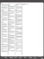
限用物質含有情況
設備名稱:互動式電子白板配件 控制器 Type 3,型號(型式):Y440
單元
限用物質及其化學符號
鉛
(Pb)
汞
(Hg)
鎘
(Cd)
六價鉻
(Cr
+6
)
多溴聯苯
(PBB)
多溴二苯醚
(PBDE)
外殼
( 外部塑膠、板金 )
-
○ ○ ○ ○ ○
電路板
-
○ ○ ○ ○ ○
連接線部件
○ ○ ○ ○ ○ ○
風扇部件
○ ○ ○ ○ ○ ○
備考 1.〝超出 0.1 wt %〞及〝超出 0.01 wt %〞係指限用物質之百分比含量超出百分比含量基準值。
備考 2.〝○〞係指該項限用物質之百分比含量未超出百分比含量基準值。
備考 3.〝-〞係指該項限用物質為排除項目。
限用物質含有情況
設備名稱:擷取迴路板,型號(型式):Y4400500
單元
限用物質及其化學符號
鉛
(Pb)
汞
(Hg)
鎘
(Cd)
六價鉻
(Cr
+6
)
多溴聯苯
(PBB)
多溴二苯醚
(PBDE)
外殼
○ ○ ○ ○ ○ ○
電路板
-
○ ○ ○ ○ ○
連接線
○ ○ ○ ○ ○ ○
備考 1.〝超出 0.1 wt %〞及〝超出 0.01 wt %〞係指限用物質之百分比含量超出百分比含量基準值。
備考 2.〝○〞係指該項限用物質之百分比含量未超出百分比含量基準值。
備考 3.〝-〞係指該項限用物質為排除項目。
進口商:台灣理光股份有限公司
地址:台北市南港區市民大道七段 8 號 12 樓之 1
이 제품은 RICOH Collaboration
Board 와만 함께 사용됩니다 기타
제품과 함께 사용할 수 없습니다 . 제품
및 안전 정보에 대한 자세한 내용은 주
장치의 설명서를 참조하십시오 .
법 및 규정
이 기기는 업무용 환경에서 사용할
목적으로 적합성평가를 받은
기기로서 가정용 환경에서
사용하는
경우 전파간섭의 우려가 있습니다 .
해당 무선설비는 전파혼신 가능성이
있으므로 인명안전과 관련된 서비스는
할 수 없습니다
DC19V
위와 같은 전원에 전기 코드를
연결하십시오 .
회사명 : ㈜리코코리아 /Ricoh Korea
Co., Ltd.
전화번호 : 1899-7225
웹사이트 : www.ricoh-korea.co.kr
List of Included Items
Liste der enthaltenen Elemente
Liste des éléments fournis
Elenco dei componenti inclusi
Lista de artículos incluidos
Lst van inbegrepen onderdelen
Liste over medfølgende artikler
Lista dos itens inclusos
Toimitukseen kuuluvat tuotteet
Lista över medföljande artiklar
Lista dołączonych elementów
包含的项目列表
包括項目清單
포함된 품목 목록
· Controller Unit
· Capture Box
· 2 antennas for controller
· Steuereinheit
· Aufzeichnungsplatine
· 2 Antennen für Controller
· Unité contrôleur
· Module de capture
· 2 antennes pour le contrôleur
· Unità controller
· Scheda di acquisizione
· 2 antenne per il controller
· Unidad controladora
· Placa de captura
· 2 antenas para el controlador
· Controllereenheid
· Capture board
· 2 controllerantennes
· Kontrollenhet
· Opptakskort
· 2 antenner til kontroller
· Unidade da controladora
· Placa de captura
· 2 antenas para a unidade de controle
· Ohjainyksikkö
· Piirtotaulu
· 2 antennia ohjaimelle
· Controller
· Minneskort
· 2 antenner till controllern
· Zespół sterownika
· Karta do przechwytywania obrazu
· 2 anteny do kontrolera
・ コントローラーボックス
・ キ ャ プ チ ャ ー ボ ッ ク ス
・ コントロー ラー 用 アンテ ナ2本
· 控制器单元
· 捕获板
· 2根控制器天线
· 控制器單元
· 擷取迴路板
· 控制器的2個天線
・컨트롤러 장치
・ 캡처 상자
・컨트롤러용 안테나 2개
Component Names and Functions
Komponentennamen und Funktionen
Noms et fonctions des composants
Nomi e funzioni dei componenti
Nombres y funciones de los componentes
Namen en functies van onderdelen
Komponentnavn og funksjoner
Nomes e funções dos componentes
Osien nimet ja toiminnot
Komponenternas namn och funktioner
Nazwy i funkcje elementów
组件名称和功能
元件名稱與功能
구성 요소 이름 및 기능
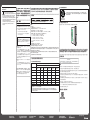
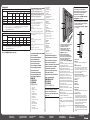
Main Unit / Hauptgerät / Appareil de base /
Unità principale / Unidad principal / Hoofdeenheid /
Ho
vedmaskin / Unidade principal / Peruslaite /
Huvudenhet / / 主单元
主機 주 장치
Y440IT0003
2
1
Controller Unit / Steuereinheit / Unité contrôleur /
Unità controller / Unidad controladora /
Controllereenheid / Kontrollenhet /
Unidade da controladora / Ohjainyksikkö /
Controller / /
/ 控制器单元 /
控制器單元 / 컨트롤러 장치
Capture Box / Aufzeichnungsplatine /
Module de capture / Scheda di acquisizione /
Placa de captura / Capture board / Opptakskort /
Placa de captura / Piirtotaulu / Minneskort /
Karta do przechwytywania obrazu /
/ 捕获板 / 擷取迴路板 /
캡처 상자
The illustration above is an example. The shape of the main
unit may differ depending on the model.
Die obige Abbildung ist ein Beispiel. Die Form der Hauptein-
heit kann je nach Modell unterschiedlich sein.
L’illustration ci-dessus est fournie à titre d’exemple. La forme
de l’unité principale peut varier selon le modèle.
L’illustrazione sopra riportata è un esempio. La forma dell’unità
principale può variare a seconda del modello.
La ilustración superior es solo un ejemplo. La forma de la
unidad principal puede variar en función del modelo.
De illustratie hierboven is een voorbeeld. De vorm van de
hoofdeenheid wijkt mogelijk af afhankelijk van het model.
Bildet over er kun et eksempel. Utformingen på hovedenheten
kan variere avhengig av modell.
A ilustração acima é um exemplo. O formato da unidade
principal varia de acordo com o modelo.
Yllä oleva kuva on esimerkki. Yksikön muoto voi vaihdella
mallista riippuen.
Bilden ovan är ett exempel. Huvudenhetens utseende kan
avvika beroende på modell.
Poniższa ilustracja jest tylko przykładowa. Wygląd urządzenia
może się różnić w zależności od modelu.
このイラストは一例です。本体の形状は機種によって
異なります 。
上方插图为一个示例。不同机型主机的外形可能不同。
上方畫面圖示為範例。主機的外形可能視機型而有
不同。
위의 그림은 예시입니다. 주 장치의 형태는 모델에
따라 다를 수 있습니다.
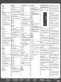
Ports on the Machine / Ports am Gerät /
Ports sur l’appareil / Porte sulla macchina /
Puertos de la máquina / Poorten op het apparaat /
Porter på maskinen / Portas no equipamento /
Laitteen liitännät / Maskinens portar /
/
机器上的端口
機器上的連接埠기기의 포트
Controller Unit / Steuereinheit / Unité contrôleur /
Unità controller / Unidad controladora / Controllereenheid/
Kontrollenhet / Unidade da controladora / Ohjainyksikkö /
Controller / /
控制器单元 控制器單
元컨트롤러 장치
8
7
1
2
3
4
5
6
DWZ004
1. SSD access LED
2. HDMI Output
A picture can be output to Audio-visual device/monitor
device.
3. USB ports (USB 3.0 Type A)
These ports are used to connect the capture box. They are
also used to connect USB memory devices for firmware
updates, saving pages, and other functions. Do not discon-
nect the capture box when connecting it. Doing so may
cause the machine to malfunction.
4. Ethernet interface (10/100/1000 Mbps)
This interface is used to connect the machine to a network.
For details about how to connect to a network, see
Operating Instructions.
5. Audio Input
6. Audio Output
7. Power LED
8. Antenna terminal
1. SSD Zugriffs-LED
2. HDMI-Ausgang
Ein Bild kann auf ein audiovisuelles Gerät/einen Monitor
ausgegeben werden.
3. USB-Ports (USB 3.0 Typ A)
Diese Anschlüsse dienen zum Anschluss der Auf-
zeichnungsplatine. Sie werden auch verwendet, um
USB-Speichergeräte für Firmware-Updates, zum Spei-
chern von Seiten und andere Funktionen anzuschließen.
Trennen Sie die Aufzeichnungsplatine nicht vom Gerät
ab, wenn diese verbunden ist. Andernfalls kann es zu
Fehlfunktionen des Geräts kommen.
4. Ethernet-Schnittstelle (10/100/1000 Mbps)
Diese Schnittstelle wird verwendet, um das Gerät mit
einem Netzwerk zu verbinden. Einzelheiten zum Verbin-
den mit einem Netzwerk fi nden Sie in der Bedienungs-
anleitung.

Read This First
Bitte zuerst lesen
À lire avant de commencer
Leggere prima di iniziare
Leer antes de empezar
Lees dit eerst
Les dette først
Leia isto primeiro
Lue tämä ensin
Läs detta först
Informacje wstępne
入门
請先閱讀本手冊
먼저 읽을 내용
5. Audioeingang
6. Audioausgang
7. Power-LED
8. Antennenanschluss
1. SSD accès LED
2. Sortie HDMI
Une image peut être transmise vers un périphérique
audiovisuel/moniteur.
3. Ports USB (USB 3.0 Type A)
Ces ports sont utilisés pour connecter le module de
capture. Ils permettent également de connecter des
périphériques USB afin d’effectuer la mise à jour du
firmware, d’enregistrer une page ou d’utiliser d’autres
fonctions. Ne déconnectez pas le module de capture
lorsqu’il est connecté. Cela pourrait entraîner des
dysfonctionnements.
4. Interface Ethernet (10/100/1000 Mbps)
Cette interface est utilisée pour connecter l’appareil à
un réseau. Pour plus d’informations sur la façon de se
connecter à un réseau, consultez le Manuel utilisateur.
5. Entrée audio
6. Sortie audio
7. Voyant d’alimentation
8. Borne d’antenne
1. LED di accesso all’unità SSD
2. Uscita HDMI
Un’immagine può essere inviata al dispositivo/monitor
audio-visivo.
3. Porte USB (USB 3.0 tipo A)
Queste porte sono utilizzate per collegare la scheda di
acquisizione. Sono inoltre utilizzate per collegare disposi-
tivi di memoria USB per gli aggiornamenti del firmware, il
salvataggio delle pagine e altre funzioni. Non scollegare
la scheda di acquisizione quando è collegata. Ciò potreb-
be causare il malfunzionamento della macchina.
4. Interfaccia Ethernet (10/100/1000 Mbps)
Questa interfaccia viene utilizzata per collegare la
macchina alla rete. Per informazioni dettagliate su come
collegarsi a una rete, consultare le Istruzioni per l’uso.
5. Ingresso audio
6. Uscita audio
7. LED di alimentazione
8. Terminale antenna
1. LED de acceso a SSD
2. Salida HDMI
Puede enviarse una imagen al dispositivo audiovisual/
dispositivo con monitor.
3. Puertos USB (USB 3.0 Tipo A)
Estos puertos se utilizan para conectar el panel de
captura. También se utilizan para conectar dispositivos
de memoria USB para actualizaciones de firmware,
guardar páginas y otras funciones. No desconecte el
panel de captura cuando esté conectado. De lo contrario,
la máquina podría averiarse.
4. Interfaz Ethernet (10/100/1000 Mbps)
Esta interfaz se usa para conectar la máquina a una red.
Si desea más información sobre cómo conectarse a una
red, consulte las Instrucciones de uso.
5. Entrada de audio
6. Salida de audio
7. LED de alimentación
8. Terminal de la antena
1. SSD-toegang LED
2. HDMI-uitgang
Een beeld kan naar een audiovisueel apparaat of moni-
tor worden overgebracht.
3. USB 3.0-poorten (type A)
Deze poorten zijn voor het aansluiten van het capture
board. U kunt ze ook gebruiken voor USB-geheugenop-
slagapparaten voor het uitvoeren van firmware-updates,
het opslaan van pagina’s, en andere functies. Verwijder
het capture board niet wanneer u die aansluit. Doet u dit
wel, dan kan dit storingen in het apparaat veroorzaken.
4. Ethernet-interface (10/100/1000 Mbps)
Deze interface wordt gebruikt om het apparaat op een
netwerk aan te sluiten. Voor meer informatie over het
aansluiten op een netwerk, zie de Gebruiksaanwijzing.
5. Audio-ingang
6. Audio-uitgang
7. Aan/uit-ledlampje
8. Antennepoort
1. LED for SSD-tilgang
2. HDMI-utgang
Du kan sende et bilde til en audiovisuell enhet/skjerm.
3. USB-porter (USB 3.0 type A)
Disse portene brukes for å koble til tilkoblingskortet. De
brukes også for å koble til USB-minneenheter for fastva-
reoppdateringer, lagring av sider, eller andre funksjoner.
Ikke koble fra tilkoblingskortet under tilkobling. Å gjøre
dette kan føre til maskinvarefeil.
4. Ethernet-grensesnitt (10/100/1000 Mbps)
Dette grensesnittet brukes til å koble maskinen til et
nettverk. Se brukerhåndboken for informasjon om hvor-
dan du kobler til et nettverk.
5. Lydinngang
6. Lydutgang
7. LED-lampe
8. Antenneterminal
1. LED de acesso a SSD
2. Saída HDMI
Uma imagem pode ser transmitida para um dispositivo
de áudio e vídeo/monitor
3. Portas USB (USB 3.0 Tipo A)
Essas portas são usadas para conectar a placa de
captura. Também são usadas para atualizar o firmware,
salvar páginas e outras funções. Não desligue a caixa de
captura enquanto estiver conectada. Caso contrário, o
equipamento poderá apresentar defeito.
4. Interface Ethernet (LAN 10/100/1000 Mbps)
Essa interface é utilizada para conectar o equipamento a
uma rede. Para mais informações sobre como se conec-
tar a uma rede, consulte as Instruções de operação.
5. Entrada de áudio
6. Saída de áudio
7. LED de energia
8. Terminal de antena
1. SSD access LED
2. HDMI-ulostulo
Kuva voidaan ohjata audiovisuaaliseen laitteeseen tai
näyttölaitteeseen.
3. USB-portit (USB 3.0 tyyppi A)
Näiden porttien kautta yhdistetään kaappauslevy. Niillä
myös yhdistetään USB-muistilaitteita, joita käytetään lai-
teohjelmistopäivityksiin, sivujen tallentamiseen ja muihin
toimintoihin. Älä irrota kaappauslevyä, kun yhdistät sen.
Tämä voi johtaa laitteen toimintahäiriöön.
4. Ethernet-liitäntä (10/100/1000 Mbps)
Laitteen verkkoliitäntä. Lisätietoja verkkoon liittämisestä
on käyttöohjeissa.
5. Äänen sisääntulo
6. Äänen ulostulo
7. Virran merkkivalo
8. Antenniliitäntä
1. SSD access LED
2. HDMI-utgång
En bild kan skrivas ut till audiovisuell enhet/visningsen-
het.
3. USB-portar (USB 3.0 typ A)
Dessa USB-anslutningar används för att ansluta Capture
box. De används även för att ansluta USB-minnen för
firmware-uppdateringar, spara sidor med mera. Koppla
inte bort Capture boxen eller när ansluter den, det kan
leda till att enheten inte fungerar korrekt.
4. Ethernet-gränssnitt (10/100/1000 Mbps)
Detta gränssnitt används för att ansluta maskinen till ett
nätverk. För mer information om hur du ansluter till ett
nätverk, se bruksanvisningen.
5. Ljudingång
6. Ljudutgång
7. Strömindikator
8. Antennterminal
1. Wskaźnik LED dostępu do SSD
2. Wyjście HDMI
Umożliwia przesłanie obrazu na urządzenie RTV/monitor.
3. Porty USB (USB 3.0 Typ A)
Porty te służą do podłączenia karty przechwytywania. Są
one również używane do podłączenia pamięci USB, do
aktualizacji oprogramowania sprzętowego, zapisywania
stron i innych funkcji. Podczas podłączania nie należy
odłączać karty przechwytywania. Może to spowodować
nieprawidłowe działanie urządzenia.
4. Interfejs sieciowy (10/100/1000 Mbps)
To gniazdo służy do podłączenia urządzenia do sieci.
Szczegółowe informacje, jak połączyć się z siecią
znajdują się w Instrukcji obsługi.
5. Wejście audio
6. Wyście audio
7. Dioda LED
8. Gniazdo antenowe
AV 機器/モニター機器へ映像を出力できます。
キャプチャ―ボックスを接続するとき、ファー
ムアップやページの保 存 など で USB メモリー
をセットするときに使用します。キャプチャー
ボックスが接続されているときは、接続を外す
と本機が正常に機能しなくなりますので、外さ
ないでください。
本機をネットワークに接続するときに使用します。
ネットワークへの接続方法は、『使用説明書』を
参照してください。
1. SSD访问LED
2. HDMI输出
图片能输出至影音设备/监控设备。
3. USB端口 (USB3.0型号A)
此类端口用于连接采集卡。端口同样可以连接
用于固件更新、保存页面或其他功能的USB存
储设备。与采集卡相连时请勿将其断开。否则
可能导致机器故障。
4. 以太网端口 (10/100/1000 Mbps)
此端口用于将机器连接至网络。有关如何连接
至网络的详细信息,请参考操作说明书。
5. 音频输入
6. 音频输出
7. 电源LED
8. 天线端子
1. SSD存取LED
2. HDMI Output
可以將圖片輸出至影音裝置/螢幕裝置。
3. USB連接埠 (USB 3.0 Type A)
這些連接埠用來連接擷取迴路板。它們也
用來連接USB記憶裝置,進行韌體更新、
儲存頁面與其他功能。連接時請勿拔除擷
取迴路板。這樣做可能造成機器故障。
4. 乙太網路介面 (10/100/1000 Mbps)
此介面用於將機器連接至網路。關於如
何連接網路的方式,請參閱「操作說明
書」。
5. 音訊輸入
6. 音訊輸出
7. 電源LED
8. 天線端子
1. SSD 액세스 LED
2. HDMI 출력
그림은 음성-시각 장치/모니터 장치로 출력할
수있습니다.
3. USB 포트(USB 3.0 A형)
이러한 포트는 액세서리를 캡처 상자와 연결하
는 데 사용됩니다. 또한 펌웨어 업데이트, 페
이지 저장 및 기타 기능을 위해 USB 메모리
장치를 연결하는 데도 사용됩니다. 연결할 때
는 액세서리나 캡처 상자의 연결을 해제하지
마십시오. 연결을 해제하는 경우 기기가 오작
동할 수 있습니다.
4. 이더넷 인터페이스(10/100/1000Mbps)
이 인터페이스는 기기를 네트워크에 연결하는
데 사용됩니다.
네트워크에 연결하는 방법에 대한 자세한 내용
은 작동 지침을 참조하십시오.
5. 오디오 입력
6. 오디오 출력
7. 전원 LED
8.안테나단자
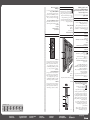
Capture Box / Aufzeichnungsplatine / Module de
capture / Scheda di acquisizione / Placa de captura /
Capture board / Opptakskort / Placa de captura /
Piirtotaulu / Minneskort / Karta do przechwytywania
obrazu /
捕获板 擷取迴路板
캡처 상자
Y440IT0001
1
2
3
1. HDMI Input
This terminal is used to connect an image output device,
such as a computer, tablet, or document camera to display
an image, and to write information on the image that is
displayed. You cannot display copyrightprotected content,
such as data on DVDs and Blu-ray discs. For details
about connecting an image output device, see Operating
Instructions.
2. DisplayPort Input
This terminal is used to connect an image output device,
such as a computer, tablet, or document camera to display
an image, and to write information on the image that is
displayed. You cannot display copyrightprotected content,
such as data on DVDs and Blu-ray discs. For details about
how to connect a computer, see Operating Instructions.
3. VGA Input
This terminal is used to connect an image output device,
such as a computer, tablet, or document camera to display
an image, and to write information on the image that is
displayed. For details about how to connect a computer,
see Operating Instructions.
1. HDMI-Eingang
Über diesen Anschluss können Sie ein Bildausgabegerät,
wie einen Computer, ein Tablet oder eine
Dokumentkamera anschließen, um ein Bild anzuzeigen
und Informationen in das angezeigte Bild zu schreiben.
Sie können keine urheberrechtlich geschützten Inhalte
anzeigen, beispielsweise Daten auf DVDs und Blu-Rays.
Details zum Anschließen eines Bildausgabegeräts erhalten
Sie in der Bedienungsanleitung.
2. DisplayPort Eingang
Über diesen Anschluss können Sie ein Bildausgabegerät,
wie einen Computer, ein Tablet oder eine
Dokumentkamera anschließen, um ein Bild anzuzeigen
und Informationen in das angezeigte Bild zu schreiben.
Sie können keine urheberrechtlich geschützten Inhalte
anzeigen, beispielsweise Daten auf DVDs und Blu-Rays.
Einzelheiten zum Anschließen eines Computers finden Sie
in der Bedienungsanleitung.
3. VGA-Eingang
Über diesen Anschluss können Sie ein Bildausgabegerät,
wie einen Computer, ein Tablet oder eine
Dokumentkamera anschließen, um ein Bild anzuzeigen
und Informationen in das angezeigte Bild zu schreiben.
Einzelheiten zum Anschließen eines Computers finden Sie
in der Bedienungsanleitung.
1. Entrée HDMI
Ce terminal est utilisé pour connecter un appareil de
sortie d’image, comme un ordinateur, une tablette ou un
appareil photo, afin d’afficher une image et d’écrire des
informations sur l’image affichée. Vous ne pouvez pas
afficher de contenu protégé par des droits d’auteur, tel
que des données sur DVD et disques Blu-ray. Pour plus
d’informations sur la connexion d’un périphérique de sortie
d’image, reportez-vous au mode d’emploi.
2. Entrée DisplayPort
Ce terminal est utilisé pour connecter un appareil de
sortie d’image, comme un ordinateur, une tablette ou un
appareil photo, afin d’afficher une image et d’écrire des
informations sur l’image affichée. Vous ne pouvez pas
afficher de contenu protégé par des droits d’auteur, tel
que des données sur DVD et disques Blu-ray. Pour plus
d’informations sur la procédure pour se connecter à un
ordinateur, consultez le Manuel utilisateur.
3. Entrée VGA
Ce terminal est utilisé pour connecter un appareil de
sortie d’image, comme un ordinateur, une tablette ou un
appareil photo, afin d’afficher une image et d’écrire des
informations sur l’image affichée. Pour plus d’informations
sur la procédure pour se connecter à un ordinateur,
consultez le Manuel utilisateur.
1. Ingresso HDMI
Questo terminale viene utilizzato per collegare un
dispositivo di uscita immagini, come un computer, un tablet
o una fotocamera documenti per visualizzare un’immagine
e per scrivere informazioni sull’immagine visualizzata. Non
è possibile visualizzare contenuti protetti da copyright,
come ad esempio dati su DVD e su dischi Blu-ray. Per
informazioni dettagliate sul collegamento di un dispositivo
di uscita immagini, consultare le Istruzioni per l’uso.
2. Ingresso DisplayPort
Questo terminale viene utilizzato per collegare un
dispositivo di uscita immagini, come un computer, un tablet
o una fotocamera documenti per visualizzare un’immagine
e per scrivere informazioni sull’immagine visualizzata. Non
è possibile visualizzare contenuti protetti da copyright,
come ad esempio dati su DVD e su dischi Blu-ray. Per
informazioni dettagliate su come collegare un computer,
consultare le Istruzioni per l’uso.
3. Ingresso VGA
Questo terminale viene utilizzato per collegare un
dispositivo di uscita immagini, come un computer, un tablet
o una fotocamera documenti per visualizzare un’immagine
e per scrivere informazioni sull’immagine visualizzata. Per
informazioni dettagliate su come collegare un computer,
consultare le Istruzioni per l’uso.
1. Entrada HDMI
Este terminal se usa para conectar un dispositivo de salida
de imágenes, como un ordenador, tableta o cámara de
documentos para mostrar una imagen y para guardar
información en la imagen que se muestra. No puede
visualizar contenido protegido por copyright, como datos
en discos DVD y Blu-ray. Para obtener más información
acerca de cómo conectar un dispositivo de salida de
imágenes, consulte las Instrucciones de uso
2. Entrada DisplayPort
Este terminal se usa para conectar un dispositivo de salida
de imágenes, como un ordenador, tableta o cámara de
documentos para mostrar una imagen y para guardar
información en la imagen que se muestra. No puede
visualizar contenido protegido por copyright, como datos
en discos DVD y Blu-ray. Si desea más información sobre
cómo conectar un ordenador, consulte las Instrucciones de
uso.
3. Entrada VGA
Este terminal se usa para conectar un dispositivo de salida
de imágenes, como un ordenador, tableta o cámara de
documentos para mostrar una imagen y para guardar
información en la imagen que se muestra. Si desea más
información sobre cómo conectar un ordenador, consulte
las Instrucciones de uso.
Seite wird geladen ...
Seite wird geladen ...
-
 1
1
-
 2
2
-
 3
3
-
 4
4
-
 5
5
-
 6
6
-
 7
7
-
 8
8


Lanier D3210 Read this first
- Typ
- Read this first
in anderen Sprachen
- English: Lanier D3210
- français: Lanier D3210
- español: Lanier D3210
- italiano: Lanier D3210
- Nederlands: Lanier D3210
- polski: Lanier D3210
- svenska: Lanier D3210
Verwandte Artikel
-
Lanier D3210 Read this first
-
-
Lanier D8600 Installationsanleitung
-
Lanier D7500 Installationsanleitung
-
Lanier D6520 Read this first
-
-
-
Lanier D6520 Installationsanleitung
-
-