
User Guide
Bedienungsanleitung
Manual de usuario
Guide de l’utilisateur
Guida per l’utente
EN, DE, ES, FR, IT


Page 1
User Guide
EN

Page 2
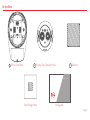
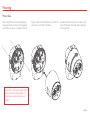
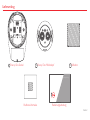
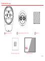
In the Box
1 Fireray One Base 2 Fireray One Detector Head 3 Reflector
Short Range Mask User guide
User Guide

Page 3
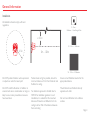
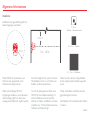
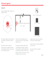
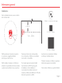
General Information
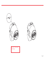
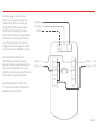
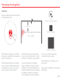
Installation
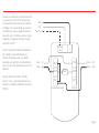
≥ 0.3m
0.5m
20 - 50m = 1 Reflector
5 - 20m =
1Reflector + Short Range Mask
50 - 120m = 4 Reflectors
5m - 120m
Position beam as high as possible, but with a
minimum distance of 0.3m from Detector and
Reflector to ceiling.
For detectors approved to UL268 refer to
NFPA72 for installation guidance. In such
installations, it is advised that the maximum
distance of Detector and Reflector from the
ceiling must be 10% of the distance between
floor and ceiling
Ensure correct Reflector selected for the
appropriate distance
Mount Detector and Reflector directly
opposite each other
Do not mount Reflector onto reflective
surfaces
Do NOT position Detector where personnel
or objects can enter the beam path
Do NOT install the Detector or Reflector in
environments where condensation or icing are
likely to occur unless preventative measures
have been taken
All installations should comply with local
regulations

Page 4
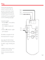
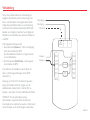
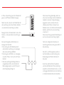
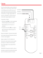
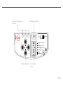
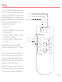
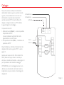
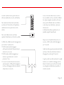
Wiring
The Fireray One contains software that
processes the output of the detector and
generates a Fire and Fault status. This status
is output using volt-free relays so that it can
be interfaced to all types of conventional Fire
Control Panel (FCP). To wire a single Detector
to an FCP, use the following wiring diagram.
Components not supplied:
1. Fire Resistor (Note 1) - value is specified by
the FCP manufacturer.
For U.S. installations it is typically a short
circuit.
2. End Of Line (‘EOL’) component - supplied
by FCP manufacturer
After installation, check operation of Fire and
Fault connections to the FCP - see page 15.
Apply a voltage of 5V to 40V to ‘Ext Reset’
contact for at least 2 seconds to clear a latched
fire condition – see page 14 for latching mode
setting.
CAUTION: For system monitoring – Do not
use looped wire under any terminals.
Breakwire run to provide monitoring of con-
nections.
Note 1
EOL
N/O
COM
N/C
N/O
COM
N/C
Ext
Reset - +
Supply +
Supply -
Ext Reset
Zone -
Zone +
Fault Fire

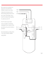
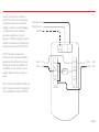
Page 5
Supply +
Supply -
Ext Reset
Zone - In
Zone +In
Note 1
Zone - Out
Zone + Out
Fault Fire
N/O
COM
N/C
N/O
COM
N/C
- +
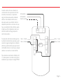
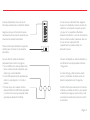
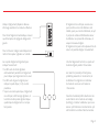
When using more than one Detector on a
single zone of a conventional FCP, it is
important to choose the correct method
of wiring. Incorrect wiring may result in a
Detector isolating subsequent devices on that
zone if it enters a Fault condition, and may
prevent these subsequent devices signalling a
Fire condition back to the FCP.
If the FCP monitors for point detector
removal, it is possible to use the following
wiring diagram which uses a diode to provide
zone continuity in the event of a Fault state on
any Detector.
Recommended diode type: Schottky, 60 Volt,
1 Amp, must be UL listed for installations
meeting NFPA72
Ext
Reset

Page 6
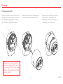
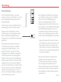
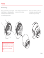
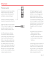
Plug the cable from the Detector head into the
connector on the PCB in the Base.
Mark and drill holes for mounting of Base.
Using appropriate hardware (not supplied)
mount base securely in orientation shown.
Locate the Detector Head on the base. Grip
sides of Detector Head and rotate clockwise
to lock together.
Ensure Base is mounted on solid surface
such as a structural wall or girder. For
mounting accessories please see our
website
Mounting
Mount Base

Page 7
Ensure the ‘Pip and Dip’
details align

Page 8
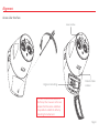
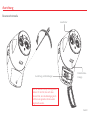
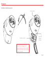
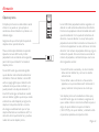
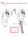
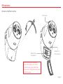
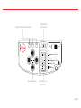
Access User Interface
Alignment
The door should remain attached to
the Fireray One, however on the rare
occasion that it becomes unattached,
it is possible to reattach the tether by
reinserting the barbed end.
Alignment and settings
Laser window
Detector Status
indicator

Page 9
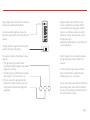
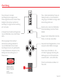
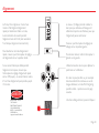
Alignment Status indicators Slide Switch
Settings Switch
Direction keys
Latching-Off/On
Targeting-Laser/Prism
Alignment-Auto/Manual
Threshold
Alarm
Fast Alignment-Off/On
Align Operate

Page 10
Stage 1 (Targeting) is the process of using the
laser to get the infra-red beam close enough to
the reflector so that Alignment can begin.
Ensure the targeting setting switch is set to the
left hand position.
To turn the laser on move the slide switch to
the left hand position.
Use the direction keys to move the laser point
on to the Reflector.
If the laser cannot be seen, for example in very
bright environments or over long distances,
then Prism Targeting mode can be used – refer
to the next page.
Once Targeting is complete, move to Stage 2.
Alignment
Fireray One will align in less than a minute if
Fast Alignment is selected. In this mode, the
current consumption during alignment will be
33mA (it will revert to 5mA when alignment is
completed).
To select fast alignment mode, ensure the fast
alignment setting switch is set to the right hand
position
If lower consumption during alignment is
required, then ensure the Fast Alignment
setting switch is set to Off – consumption will
remain at 5mA but alignment can take up to
15 minutes.
DANGER
LASER RADIATION - AVOID
DIRECT EYE EXPOSURE
POWER OUTPUT < 5mW-
CLASS IIIa LASER
Wavelength 630 - 680 nm

Page 11
Stage 2 (Alignment) moves the infra-red beam
exactly to the middle of the Reflector.
To select auomatic alignment, ensure the
alignment setting switch is set to the left hand
position.
To begin automatic alignment move the slide
switch to the right hand position.
The alignment status LEDs will flash to show
progress:
• The right-hand green LED will flash
continually throughout alignment to indicate
alignment is occurring
• The left-hand green LED flashes to indicate
which stage (1 to 4) the process is at.
• If for any reason the alignment fails the
amber LED will flash, and the number of
times it flashes indicates which alignment
stage failed.
If alignment fails, ensure that the correct
number of reflectors are installed, that the
correct clearance has been given, and that
there are no reflective surfaces around the
reflector or close to the beam path, and try
the alignment again.
If alignment repeatedly fails, it is possible to do
a manual alignment.
Once the alignment is successfully complete,
the right-hand green LED will flash for 10
seconds.
The Fire and Fault relays will go to normal
state, and the Detector will flash its status
indicator green every 10 seconds.
You are now ready to select Alarm Thresholds
and Latching mode, and to test the Detector
to ensure it is operating and connected to the
Fire Control Panel correctly.

Page 12
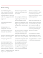
Alignment
Prism targeting should only be used when
the laser cannot be seen, for instance in high
ambient lighting conditions or over very long
distances.
Ensure targeting setting switch is in the right
hand position.
Move the slide switch to the left position.
The green and amber LEDs will flash together
for a few seconds to show the detector has
started Prism targeting.
If the green LED stays illuminated the
Detector is receiving enough light back from
the Reflector. Cover the reflector – if the green
LED goes off then the light being received by
the Detector is coming from the Reflector and
you can now proceed to the Alignment stage.
If the green LED stays illuminated with the
reflector covered then the light received by
the detector is being reflected by some other
object in or around the beam path. Take care
to make sure there are no reflective objects
within 0.5m of the centre of the beam path,
and try Prism Targeting again.
Prism targeting
The amber LED will flash every two seconds if
the Detector is not receiving enough light from
the Reflector. The number of flashes indicate
how strong a signal it is receiving. Using the
direction buttons, move the detector in one
axis until the amber flashes increase. If the
number of flashes stays the same, then keep
going in the same direction. If the number
decreases then reverse direction. Once the
number of flashes starts to increase then keep
going until either:
• The green LED comes on, at which point
cover the reflector as described above
• The amber flashes start to decrease again, at
which point reverse direction for 2 steps and
perform the same process in the other axis
If Prism Targeting has been performed on both
axes and the green LED is still not on then
ensure that the correct number of reflectors
for the range has been used, that the distance
has not exceeded the maximum (120m/394ft)
and that the reflector and detector are parallel
to each other.

Page 13
Manual Alignment
Manual alignment should only be used when
Automatic alignment has failed even after it
has been verified that the correct number of
reflectors have been installed and the correct
clearance around the beam path has been
given.
Perform targeting as previously described
Ensure Setting Switch 1 is in the right-hand
position, and move the Slide Switch to the
right-hand position
The green and amber LEDs may flash if the
detector needs to perform an initial power
adjustment
Once the LEDs have stopped flashing, use
the direction buttons to move the detector
in the up-down axis. First, use the direction
button in the down direction. Press the button
once, and wait to see what the LED indication
shows. If both amber and green LEDs flash,
the signal has not changed so no further
movement in that axis is needed.
If the amber LED flashes, the signal is smaller
and the detector is moved away from the
reflector. The next movement must be in
the opposite direction. Using the direction
buttons, move the detector again – this time
there should be a green flash.
If the green LED flashes, the signal is larger and
the detector is moving closer to the reflector.
The next movement must be in the same
direction. Keep moving the detector, waiting
for the LED flash each time. If the green
LED keeps flashing, keep going in the same
direction. If the amber and the green LED
flashes, then move onto the other axis. If the
amber LED flashes, move back in the opposite
direction once, then move onto the other axis.
Follow the same process with the direction
buttons, this time in the left-right axis. Start by
moving the left direction, and follow the same
LED flashes as described in the up-down axis.
Once the alignment has been completed on
both axis then move Setting Switch 1 to the
left-hand position. The right-hand green LED
will flash for 10s, the Fire and Fault relays will
go to normal state, and the Detector will flash
its status indicator green every 10 seconds.
You are now ready to select Alarm Thresholds
and Latching mode, and to test the Detector
to ensure it is operating and connected to the
Fire Control Panel correctly.

Page 14
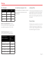
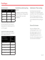
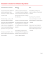
Settings
Fire Threshold
EN54-12 Threshold Selection: Only the
25% and 35% thresholds are approved. Both
are suitable for separations of 5m to 120m.
UL268 Threshold Selection: Select the
correct threshold for the installed distance:
Threshold SW5 SW6
25% On On
35% Off Off
55% On Off
85% Off On
The Fire state will automatically clear once the
signal strength has recovered unless Latching
Mode has been selected. To select Latching
Mode move the Latching Mode switch to the
On position.
Separation between
Detector and Reflector
Acceptable
Alarm
Thresholds
<25ft (<7.5m) 25%
25 – 55ft (7.5 – 16.5m) 25%, 35%
55 – 110ft (16.5 – 33.5m) 35%, 55%
110 – 175ft (33.5 – 53m) 55%, 85%
175 – 394ft (53 – 120m) 85%
External Reset
Latching Mode
If Latching mode is selected then to clear a fire
condition remove power for longer than 10
seconds or apply a voltage of greater than 5V
to Ext-Rst for longer than 2 seconds.
Successful alignment of the Detector will check
correct operation of the Detector and its
sensitivity level.
UL Sensitivity Acceptance Test

Page 15
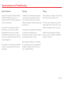
Status Indications and Troubleshooting
During normal operation the Detector Status
indicator LED will flash green every 10
seconds, and both Fire and Fault relays will be
in their normal position.
If the detector is in Fault state, its LED will
flash amber every 10 seconds to indicate
Signal High/Low Fault, every 5 seconds to
indicate AGC/Compensation Fault, and every
3 seconds to indicate Internal Fault. The Fault
relay will change state.
If the detector is in Fire state, its LED will flash
red every 10 seconds and the Fire relay will
change state.
The Detector will automatically compensate
for dust build up by changing its AGC level.
Once the AGC limit has been reached, the
Detector will indicate a Fault and cleaning must
be performed.
It is therefore recommended that the Detector
lens windows and the Reflector are
periodically cleaned with a soft lint-free cloth to
prevent AGC limit faults occurring.
After cleaning, if the Detector is in Fault state,
the signal strength may have increased above
the Signal Too High threshold. If this is the
case, re-align the Detector.
After installation or cleaning it is recommended
that a Fire and Fault test is performed.
Fire Test: Cover the reflector slowly so that
it takes longer than 5 seconds to cover. The
Detector will indicate Fire after 10 seconds.
Fault Test: Cover the reflector completely
within 2 seconds. The Detector will indicate
Fault after 10 seconds.
Status Indications Cleaning Testing

Page 16
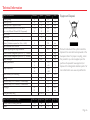
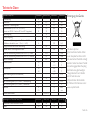
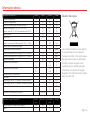
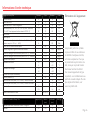
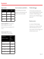
Technical Information
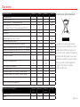
Fireray One Parameters Minimum Typical Maximum Unit
Operating Voltage 14 - 36 V
Operating Current 4.5 5.0 5.5 mA
Operating Current – Alignment Modes 31 33 35 mA
Response Thresholds (25%, 35%, 55%, 85%)
(note – only 25% and 35% are EN54-12 approved)
1.25
25
1.87
35
8.24
85
dB
%
Delay to Alarm - 10 - s
Delay to Fault - 10 - s
Operating Distance (Separation between Detector and
Reflector) (4 reflectors required for >50m, >164ft)
5
16
- 120
394
m
feet
Rapid Obscuration Fault Threshold - 85 - %
Maximum angular alignment range of detector - - ±4.5 Deg
Tolerance to beam misalignment (per EN54-12) – Detector - ±0.5 - Deg
Tolerance to beam misalignment (per EN54-12) – Reflector - ±5 - Deg
Optical Wavelength - 850 - nm
Operating Temperature -20
-4
-
-
+55
+131
°C
°F
Storage Temperature -40
-40
-
-
+85
+185
°C
°F
Relative Humidity (non-condensing) - - 93 %RH
IP rating - 55 - -
Fire & Fault Relays (VFCO, Resistive) - Contact voltage - - 30 V DC
Fire & Fault Relays (VFCO, Resistive) - Contact current - - 2 A
Cable gauge 22
0.5
-
-
14
1.6
AWG
mm
Housing flammability rating - UL940 V0 - -
Fireray One Dimensions and Weights Width (mm) Height (mm) Depth (mm) Weight (kg)
Reflective Detector, including smart base 134 182 151 0.7
Reflector 100 100 10 0.1
Products marked with this symbol cannot be
disposed of as unsorted municipal waste in the
European Union. For proper recycling, return
this product to your local supplier upon the
purchase of equivalent new equipment, or
dispose of it at designated collection points. For
more information see: www.recyclethis.info.
Equipment Disposal

Seite 1
Bedienungsanleitung
DE

Seite 2
Lieferumfang
1 Fireray One Sockel 2 Fireray One Melderkopf 3 Reflektor
Nahbereichsmaske Bedienungsanleitung
Bedienungsanleitung
Seite wird geladen ...
Seite wird geladen ...
Seite wird geladen ...
Seite wird geladen ...
Seite wird geladen ...
Seite wird geladen ...
Seite wird geladen ...
Seite wird geladen ...
Seite wird geladen ...
Seite wird geladen ...
Seite wird geladen ...
Seite wird geladen ...
Seite wird geladen ...
Seite wird geladen ...
Seite wird geladen ...
Seite wird geladen ...
Seite wird geladen ...
Seite wird geladen ...
Seite wird geladen ...
Seite wird geladen ...
Seite wird geladen ...
Seite wird geladen ...
Seite wird geladen ...
Seite wird geladen ...
Seite wird geladen ...
Seite wird geladen ...
Seite wird geladen ...
Seite wird geladen ...
Seite wird geladen ...
Seite wird geladen ...
Seite wird geladen ...
Seite wird geladen ...
Seite wird geladen ...
Seite wird geladen ...
Seite wird geladen ...
Seite wird geladen ...
Seite wird geladen ...
Seite wird geladen ...
Seite wird geladen ...
Seite wird geladen ...
Seite wird geladen ...
Seite wird geladen ...
Seite wird geladen ...
Seite wird geladen ...
Seite wird geladen ...
Seite wird geladen ...
Seite wird geladen ...
Seite wird geladen ...
Seite wird geladen ...
Seite wird geladen ...
Seite wird geladen ...
Seite wird geladen ...
Seite wird geladen ...
Seite wird geladen ...
Seite wird geladen ...
Seite wird geladen ...
Seite wird geladen ...
Seite wird geladen ...
Seite wird geladen ...
Seite wird geladen ...
Seite wird geladen ...
Seite wird geladen ...
Seite wird geladen ...
Seite wird geladen ...
-
 1
1
-
 2
2
-
 3
3
-
 4
4
-
 5
5
-
 6
6
-
 7
7
-
 8
8
-
 9
9
-
 10
10
-
 11
11
-
 12
12
-
 13
13
-
 14
14
-
 15
15
-
 16
16
-
 17
17
-
 18
18
-
 19
19
-
 20
20
-
 21
21
-
 22
22
-
 23
23
-
 24
24
-
 25
25
-
 26
26
-
 27
27
-
 28
28
-
 29
29
-
 30
30
-
 31
31
-
 32
32
-
 33
33
-
 34
34
-
 35
35
-
 36
36
-
 37
37
-
 38
38
-
 39
39
-
 40
40
-
 41
41
-
 42
42
-
 43
43
-
 44
44
-
 45
45
-
 46
46
-
 47
47
-
 48
48
-
 49
49
-
 50
50
-
 51
51
-
 52
52
-
 53
53
-
 54
54
-
 55
55
-
 56
56
-
 57
57
-
 58
58
-
 59
59
-
 60
60
-
 61
61
-
 62
62
-
 63
63
-
 64
64
-
 65
65
-
 66
66
-
 67
67
-
 68
68
-
 69
69
-
 70
70
-
 71
71
-
 72
72
-
 73
73
-
 74
74
-
 75
75
-
 76
76
-
 77
77
-
 78
78
-
 79
79
-
 80
80
-
 81
81
-
 82
82
-
 83
83
-
 84
84


in anderen Sprachen
- English: Potter Fireray One User manual
- français: Potter Fireray One Manuel utilisateur
- español: Potter Fireray One Manual de usuario
- italiano: Potter Fireray One Manuale utente
Andere Dokumente
-
Cooper MBD100R Benutzerhandbuch
-
Honeywell 805595 Benutzerhandbuch
-
System Sensor 6500-MMK Benutzerhandbuch
-
Hager TG550A 2 Installationsanleitung
-
Abus LS2030 Benutzerhandbuch
-
-
D+H RZN 4503-T Bedienungsanleitung
-
D+H RZN 4404-K V2 Bedienungsanleitung
-
-
D+H RZN 4416-M Bedienungsanleitung