MSI A320M GAMING PRO Benutzerhandbuch
- Kategorie
- Motherboards
- Typ
- Benutzerhandbuch
Dieses Handbuch eignet sich auch für

1
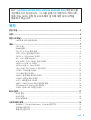
< 1> Contents
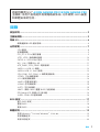
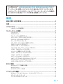
Contents
Safety Information ........................................................................................... 2
Specifications ...................................................................................................3
Rear I/O Panel .................................................................................................6
LAN Port LED Status Table ................................................................................6
Overview of Components ................................................................................7
CPU Socket .........................................................................................................8
DIMM Slots .........................................................................................................9
PCI_E1~3: PCIe Expansion Slots........................................................................9
JFP1, JFP2: Front Panel Connectors ...............................................................10
SATA1~4: SATA 6Gb/s Connectors ...................................................................10
M2_1: M.2 Slot (Key M) .....................................................................................11
ATX_PWR1, CPU_PWR1: Power Connectors ...................................................11
JUSB1~2: USB 2.0 Connectors ........................................................................12
JUSB3: USB 3.1 Gen1 Connector .....................................................................12
CPU_FAN1, SYS_FAN1~2: Fan Connectors .....................................................13
JTPM1: TPM Module Connector.......................................................................14
JCI1: Chassis Intrusion Connector ..................................................................14
JAUD1: Front Audio Connector ........................................................................15
JCOM1: Serial Port Connector .........................................................................15
JLPT1: Parallel Port Connector .......................................................................15
JBAT1: Clear CMOS (Reset BIOS) Jumper .......................................................16
EZ Debug LED: Debug LED indicators .............................................................16
JLED1: RGB LED connector .............................................................................16
BIOS Setup ..................................................................................................... 17
Entering BIOS Setup.........................................................................................17
Resetting BIOS .................................................................................................18
Updating BIOS ..................................................................................................18
Software Description .....................................................................................19
Installing Windows
®
7 64-bit/ Windows
®
10 64-bit ..........................................19
Installing Drivers ..............................................................................................19
Installing Utilities .............................................................................................20
Thank you for purchasing the MSI
®
A320M GAMING PRO/
B350M GAMING PRO motherboard. This User Guide gives
information about board layout, component overview, BIOS
setup and software installation.

2
Safety Information
Safety Information
y The components included in this package are prone to damage from electrostatic
discharge (ESD). Please adhere to the following instructions to ensure successful
computer assembly.
y Ensure that all components are securely connected. Loose connections may cause
the computer to not recognize a component or fail to start.
y Hold the motherboard by the edges to avoid touching sensitive components.
y It is recommended to wear an electrostatic discharge (ESD) wrist strap when
handling the motherboard to prevent electrostatic damage. If an ESD wrist strap
is not available, discharge yourself of static electricity by touching another metal
object before handling the motherboard.
y Store the motherboard in an electrostatic shielding container or on an anti-static
pad whenever the motherboard is not installed.
y Before turning on the computer, ensure that there are no loose screws or metal
components on the motherboard or anywhere within the computer case.
y Do not boot the computer before installation is completed. This could cause
permanent damage to the components as well as injury to the user.
y If you need help during any installation step, please consult a certified computer
technician.
y Always turn off the power supply and unplug the power cord from the power outlet
before installing or removing any computer component.
y Keep this user guide for future reference.
y Keep this motherboard away from humidity.
y Make sure that your electrical outlet provides the same voltage as is indicated on
the PSU, before connecting the PSU to the electrical outlet.
y Place the power cord such a way that people can not step on it. Do not place
anything over the power cord.
y All cautions and warnings on the motherboard should be noted.
y If any of the following situations arises, get the motherboard checked by service
personnel:
Liquid has penetrated into the computer.
The motherboard has been exposed to moisture.
The motherboard does not work well or you can not get it work according to user
guide.
The motherboard has been dropped and damaged.
The motherboard has obvious sign of breakage.
y Do not leave this motherboard in an environment above 60C (140F), it may
damage the motherboard.

3
Safety Information Specifications
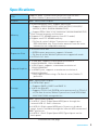
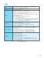
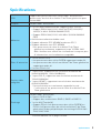
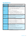
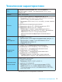
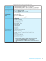
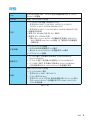
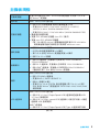
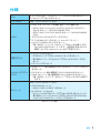
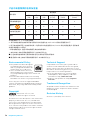
Specifications
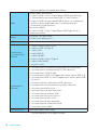
CPU
Supports AMD
®
RYZEN series processors and 7th Gen
A-series/ Athlon™ processors for Socket AM4
Chipset AMD
®
A320/ B350 Chipset
Memory
y 2x DDR4 memory slots, support up to 32GB
Supports DDR4 1866/ 2133/ 2400/ 2667(OC)/ 2933(OC)/
3200(OC)+ MHz* (B350M GAMING PRO)
Support DDR4 1866/ 2133/ 2400 MHz* (A320M GAMING PRO)
y
Dual channel memory architecture
y
Supports ECC UDIMM memory (non-ECC mode)
y
Support non-ECC UDIMM memory
* 7th Gen A-series/ Athlon ™ processors support up to
DDR 2400 MHz only. Please refer www.msi.com for more
information on compatible memory.
Expansion Slots
y 1x PCIe 3.0 x16 slot
RYZEN series processors support x16 mode
7th Gen A-series/ Athlon™ processors support x8 mode
y 2x PCIe 2.0 x1 slots
Onboard Graphics
y 1x VGA port, supports a maximum resolution of
2048x1280@60Hz, 1920x1200@60Hz*
y 1x DVI-D port, supports a maximum resolution of
1920x1200@60Hz*
y 1x HDMI™ port, supports a maximum resolution of
4096x2160@24Hz*
* Only support when using a 7th Gen A-series/ Athlon ™
processor.
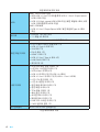
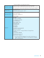
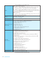
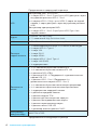
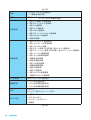
Storage
AMD
®
A320/ B350 Chipset
y 4x SATA 6Gb/s ports
Supports RAID 0, RAID1 and RAID 10
y 1x M.2 slot (Key M)
Supports PCIe 3.0 x4 (RYZEN series processors) or PCIe 3.0
x2 (7th Gen A-series/ Athlon™ processors) and SATA 6Gb/s
2242/ 2260 /2280 storage devices
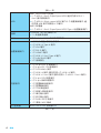
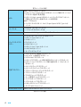
USB
AMD
®
A320/ B350 Chipset
y 2x USB 3.1 Gen1 (SuperSpeed USB) ports through the
internal USB 3.1 Gen1 connector
y 6x USB 2.0 (High-speed USB) ports (2 ports on the back
panel, 4 ports available through the internal USB connectors)
AMD
®
processor
y 4x USB 3.1 Gen1 (SuperSpeed USB) Type-A ports on the
back panel
Continued on next page

4
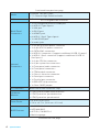
Specifications
Continued from previous page
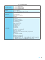
Audio
y Realtek
®
ALC887 Codec
y 7.1-Channel High Definition Audio
LAN 1x Realtek
®
8111H Gigabit LAN controller
Back Panel
Connectors
y 1x PS/2 keyboard/ mouse combo port
y 2x USB 2.0 Type-A ports
y 1x VGA port
y 1x DVI-D port
y 1x HDMI™ port
y 4x USB 3.1 Gen1 Type-A ports
y 1x LAN (RJ45) port
y 3x audio jacks
Internal
Connectors
y 1x 24-pin ATX main power connector
y 1x 8-pin ATX 12V power connector
y 4x SATA 6Gb/s connectors
y 2x USB 2.0 connectors (supports additional 4 USB 2.0 ports)
y 1x USB 3.1 Gen1 connector (supports additional 2 USB 3.1
Gen1 ports)
y 1x 4-pin CPU fan connector
y 2x 4-pin system fan connectors
y 1x Front panel audio connector
y 2x Front panel connectors
y 1x TPM module connector
y 1x Chassis Intrusion connector
y 1x Serial port connector
y 1x Parallel port connector
y 1x RGB LED strip connector
y 1x Clear CMOS jumper
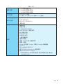
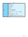
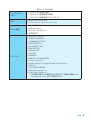
I/O Controller NUVOTON 6795D Controller Chip
Hardware
Monitor
y CPU/System temperature detection
y CPU/System fan speed detection
y CPU/System fan speed control
Form Factor
y m-ATX Form Factor
y 9.6 in. x 8.7 in. (24.4 cm x 21.0 cm)
BIOS Features
y 1x 128 Mb flash
y UEFI AMI BIOS
y ACPI 5.0, SM BIOS 3.0
y Multi-language
Continued on next page

5
Specifications Specifications
Continued from previous page
Software
y Drivers
y SUPER CHARGER
y COMMAND CENTER
y LIVE UPDATE 6
y MSI SMART TOOL
y DRAGON EYE
y GAMING APP
y X-BOOST
y RAMDISK
y GAMING LAN MANAGER
y Norton
™
Security
y Google Chrome
™
,Google Toolbar, Google Drive
y WTFast*
y CPU-Z MSI GAMING
y XSplit Gamecaster V2
y SteelSeries Engine 3
* This offer is valid for a limited period only, for more
information please visit www.msi.com

6
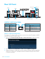
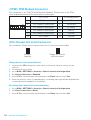
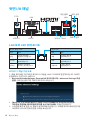
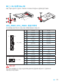
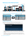
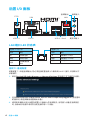
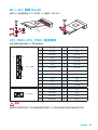
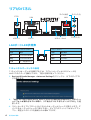
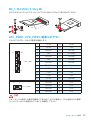
Rear I/O Panel
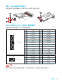
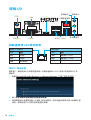
Rear I/O Panel
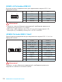
Link/ Activity LED
Status Description
Off No link
Yellow Linked
Blinking Data activity
Speed LED
Status Description
Off 10 Mbps connection
Green 100 Mbps connection
Orange 1 Gbps connection
LAN Port LED Status Table
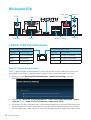
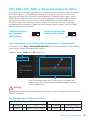
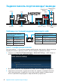
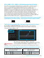
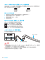
Audio 7.1-channel Configuration
To configure 7.1-channel audio, you have to connect front audio I/O module to JAUD1
connector and follow the below steps.
1. Click on the Realtek HD Audio Manager > Advanced Settings to open the dialog
below.
2. Select Mute the rear output device, when a front headphone plugged in.
3. Plug your speakers to audio jacks on rear and front I/O panel. When you plug into
a device at an audio jack, a dialogue window will pop up asking you which device
is current connected.
PS/2
LAN
USB 3.1 Gen1USB 2.0
DVI-D
VGA
Line-in
Line-out
Mic in

7
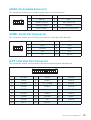
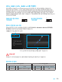
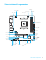
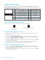
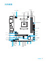
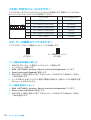
Rear I/O Panel Overview of Components
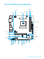
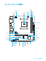
CPU_FAN1
CPU Socket
SYS_FAN1
PCI_E3
JTPM1
PCI_E2
M2_1
PCI_E1
DIMMA1
DIMMB1
JBAT1
JCI1
JFP2
JLED1
JFP1
ATX_PWR1
CPU_PWR1
EZ Debug LED
SATA3
SATA4
JLPT1
JUSB2
JUSB1
SYS_FAN2
JUSB3
JCOM1
JAUD1
SATA12
Overview of Components

8
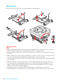
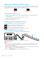
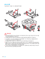
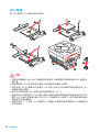
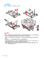
Overview of Components
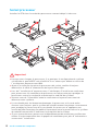
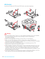
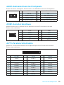
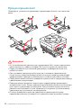
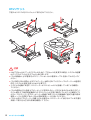
CPU Socket
Please install the CPU into the CPU socket as shown below.
Important
y
When changing the processor, the system configuration could be cleared and reset
BIOS to default values due to the AM4 processors architecture.
y
Always unplug the power cord from the power outlet before installing or removing
the CPU.
y
When installing a CPU, always remember to install a CPU heatsink. A CPU heatsink
is necessary to prevent overheating and maintain system stability.
y
Confirm that the CPU heatsink has formed a tight seal with the CPU before booting
your system.
y
Overheating can seriously damage the CPU and motherboard. Always make sure
the cooling fans work properly to protect the CPU from overheating. Be sure to
apply an even layer of thermal paste (or thermal tape) between the CPU and the
heatsink to enhance heat dissipation.
y
If you purchased a separate CPU and heatsink/ cooler, Please refer to the
documentation in the heatsink/ cooler package for more details about installation.
1
3
5
4
6
7
8
2

9
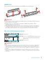
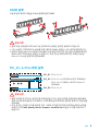
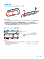
Overview of Components Overview of Components
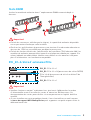
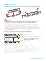
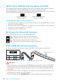
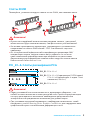
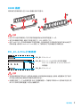
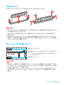
DIMM Slots
Please install the memory module into the DIMM slot as shown below.
Important
y
Due to chipset resource usage, the available capacity of memory will be a little less
than the amount of installed.
y
Based on processor specification, the Memory DIMM voltage below 1.35V is
suggested to protect the processor.
y
Due to AM4 CPU/memory controller official specification limitation, the frequency
of memory modules may operate lower than the marked value under the default
state. Please refer www.msi.com for more information on compatible memory.
PCI_E1~3: PCIe Expansion Slots
PCI_E1: PCIe 2.0 x1
PCI_E2: PCIe 3.0 x16 (RYZEN Series processors)
PCIe 3.0 x8 (7th Gen A-series/ Athlon™
processors)
PCI_E3: PCIe 2.0 x1
Important
y
When adding or removing expansion cards, always turn off the power supply and
unplug the power supply power cable from the power outlet. Read the expansion
cards documentation to check for any necessary additional hardware or software
changes.
y
If you install a large and heavy graphics card, you need to use a tool such as MSI
Gaming Series Graphics Card Bolster to support its weight to prevent deformation
of the slot.
1
1
2
3
3
2

10
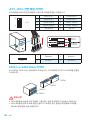
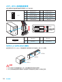
Overview of Components
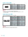
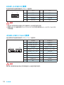
SATA1~4: SATA 6Gb/s Connectors
These connectors are SATA 6Gb/s interface ports. Each connector can connect to one
SATA device.
SATA1
SATA2
SATA3
SATA4
Important
y
Please do not fold the SATA cable at a 90-degree angle. Data loss may result during
transmission otherwise.
y
SATA cables have identical plugs on either sides of the cable. However, it is
recommended that the flat connector be connected to the motherboard for space
saving purposes.
JFP1, JFP2: Front Panel Connectors
These connectors connect to the switches and LEDs on the front panel.
1
2
10
9
JFP1
1 HDD LED + 2 Power LED +
3 HDD LED - 4 Power LED -
5 Reset Switch 6 Power Switch
7 Reset Switch 8 Power Switch
9 Reserved 10 No Pin
1
JFP2
1 Speaker - 2 Buzzer +
3 Buzzer - 4 Speaker +
HDD LED
RESET SW
HDD LED
HDD LED -
HDD LED +
POWER LED -
POWER LED +
POWER LED
JFP1

11
Overview of Components Overview of Components
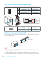
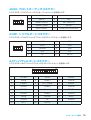
ATX_PWR1, CPU_PWR1: Power Connectors
These connectors allow you to connect an ATX power supply.
24
131
12
ATX_PWR1
1 +3.3V 13 +3.3V
2 +3.3V 14 -12V
3 Ground 15 Ground
4 +5V 16 PS-ON#
5 Ground 17 Ground
6 +5V 18 Ground
7 Ground 19 Ground
8 PWR OK 20 Res
9 5VSB 21 +5V
10 +12V 22 +5V
11 +12V 23 +5V
12 +3.3V 24 Ground
5
4
1
8
CPU_PWR1
1 Ground 5 +12V
2 Ground 6 +12V
3 Ground 7 +12V
4 Ground 8 +12V
Important
Make sure that all the power cables are securely connected to a proper ATX power
supply to ensure stable operation of the motherboard.
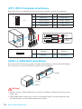
M2_1: M.2 Slot (Key M)
Please install the M.2 solid-state drive (SSD) into the M.2 slot as shown below.
1
2
3
4
5
30

12
Overview of Components
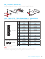
JUSB3: USB 3.1 Gen1 Connector
This connector allows you to connect USB 3.1 Gen1 ports on the front panel.
1 10
1120
1 Power 11 USB2.0+
2 USB3_RX_DN 12 USB2.0-
3 USB3_RX_DP 13 Ground
4 Ground 14 USB3_TX_C_DP
5 USB3_TX_C_DN 15 USB3_TX_C_DN
6 USB3_TX_C_DP 16 Ground
7 Ground 17 USB3_RX_DP
8 USB2.0- 18 USB3_RX_DN
9 USB2.0+ 19 Power
10 NC 20 No Pin
Important
Note that the Power and Ground pins must be connected correctly to avoid possible
damage.
JUSB1~2: USB 2.0 Connectors
These connectors allow you to connect USB 2.0 ports on the front panel.
1
2 10
9
1 VCC 2 VCC
3 USB0- 4 USB1-
5 USB0+ 6 USB1+
7 Ground 8 Ground
9 No Pin 10 NC
Important
y
Note that the VCC and Ground pins must be connected correctly to avoid possible
damage.
y
In order to recharge your iPad,iPhone and iPod through USB ports, please install
MSI
®
SUPER CHARGER utility.

13
Overview of Components Overview of Components
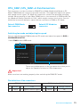
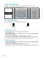
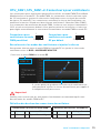
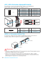
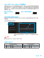
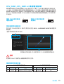
CPU_FAN1, SYS_FAN1~2: Fan Connectors
Fan connectors can be classified as PWM (Pulse Width Modulation) Mode or DC
Mode. PWM Mode fan connectors provide constant 12V output and adjust fan speed
with speed control signal. DC Mode fan connectors control fan speed by changing
voltage. When you plug a 3-pin (Non-PWM) fan to a fan connector in PWM mode, the
fan speed will always maintain at 100%, which might create a lot of noise. You can
follow the instruction below to adjust the fan connector to PWM or DC Mode.
Switching fan mode and adjusting fan speed
You can switch between PWM mode and DC mode and adjust fan speed in BIOS >
HARDWARE MONITOR.
Select PWM mode or DC mode
Important
Make sure fans are working properly after switching the PWM/ DC mode.
There are gradient points of the fan speed that allow you to
adjust fan speed in relation to CPU temperature.
Default PWM Mode
fan connector
Default DC Mode fan
connector
1
CPU_FAN1
1
SYS_FAN1/ 2
PWM Mode pin definition
1 Ground 2 +12V
3 Sense 4 Speed Control Signal
DC Mode pin definition
1 Ground 2 Voltage Control
3 Sense 4 NC
Pin definition of fan connectors

14
Overview of Components
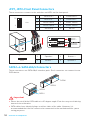
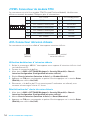
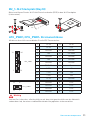
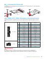
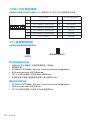
JTPM1: TPM Module Connector
This connector is for TPM (Trusted Platform Module). Please refer to the TPM
security platform manual for more details and usages.
1
2 14
13
1 LPC Clock 2 3V Standby power
3 LPC Reset 4 3.3V Power
5 LPC address & data pin0 6 Serial IRQ
7 LPC address & data pin1 8 5V Power
9 LPC address & data pin2 10 No Pin
11 LPC address & data pin3 12 Ground
13 LPC Frame 14 Ground
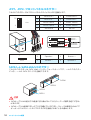
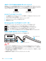
JCI1: Chassis Intrusion Connector
This connector allows you to connect the chassis intrusion switch cable.
Normal
(default)
Trigger the chassis
intrusion event
Using chassis intrusion detector
1. Connect the JCI1 connector to the chassis intrusion switch/ sensor on the
chassis.
2. Close the chassis cover.
3. Go to BIOS > SETTINGS > Security > Chassis Intrusion Configuration.
4. Set Chassis Intrusion to Enabled.
5. Press F10 to save and exit and then press the Enter key to select Yes.
6. Once the chassis cover is opened again, a warning message will be displayed on
screen when the computer is turned on.
Resetting the chassis intrusion warning
1. Go to BIOS > SETTINGS > Security > Chassis Intrusion Configuration.
2. Set Chassis Intrusion to Reset.
3. Press F10 to save and exit and then press the Enter key to select Yes.

15
Overview of Components Overview of Components
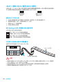
JAUD1: Front Audio Connector
This connector allow you to connect audio jacks on the front panel.
1
2 10
9
1 MIC L 2 Ground
3 MIC R 4 NC
5 Head Phone R 6 MIC Detection
7 SENSE_SEND 8 No Pin
9 Head Phone L 10 Head Phone Detection
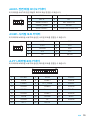
JCOM1: Serial Port Connector
This connector allows you to connect the optional serial port with bracket.
1
2 10
9
1 DCD 2 SIN
3 SOUT 4 DTR
5 Ground 6 DSR
7 RTS 8 CTS
9 RI 10 No Pin
1
2 26
25
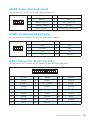
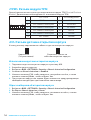
1 RSTB# 2 AFD# 3 PRND0
4 ERR# 5 PRND1 6 PINIT#
7 PRND2 8 LPT_SLIN# 9 PRND3
10 Ground 11 PRND4 12 Ground
13 PRND5 14 Ground 15 PRND6
16 Ground 17 PRND7 18 Ground
19 ACK# 20 Ground 21 BUSY
22 Ground 23 PE 24 Ground
25 SLCT 26 No Pin
JLPT1: Parallel Port Connector
This connector allows you to connect the optional parallel port with bracket.

16
Overview of Components
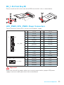
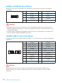
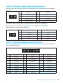
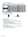
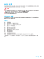
JBAT1: Clear CMOS (Reset BIOS) Jumper
There is CMOS memory onboard that is external powered from a battery located on
the motherboard to save system configuration data. If you want to clear the system
configuration, set the jumpers to clear the CMOS memory.
Keep Data
(default)
Clear CMOS/ Reset
BIOS
Resetting BIOS to default values
1. Power off the computer but DO NOT unplug the power cord (system under S5/
Soft-off mode).
2. Use a jumper cap to short JBAT1 for about 5-10 seconds.
3. Remove the jumper cap from JBAT1.
4. Power on the computer.
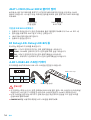
EZ Debug LED: Debug LED indicators
These LEDs indicate the status of the motherboard.
CPU - indicates CPU is not detected or fail.
DRAM - indicates DRAM is not detected or fail.
VGA - indicates GPU is not detected or fail.
BOOT - indicates booting device is not detected or fail.
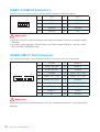
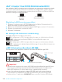
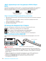
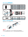
JLED1: RGB LED strip connector
This connector allows you to connect the 5050 RGB LED strip.
Important
y
This connector supports 5050 RGB multi-color LED strips (12V/G/R/B) with the
maximum power rating of 3A (12V). Please keeping the LED strip shorter than 2
meters to prevent dimming.
y
Always turn off the power supply and unplug the power cord from the power outlet
before installing or removing the RGB LED strip.
y
Please use GAMING APP to control the extended LED strip.
1
JLED1
Extension cable (optional)
5050 LED strip
1
1 +12V 2 G
3 R 4 B

17
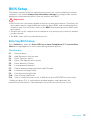
Overview of Components BIOS Setup
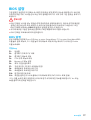
BIOS Setup
The default settings offer the optimal performance for system stability in normal
conditions. You should always keep the default settings to avoid possible system
damage or failure booting unless you are familiar with BIOS.
Important
y
BIOS items are continuous update for better system performance. Therefore, the
description may be slightly different from the latest BIOS and should be held for
reference only. You could also refer to the HELP information panel for BIOS item
description.
y
The pictures in this chapter are for reference only and may vary from the product
you purchased.
y
The BIOS items will vary with the processor.
Entering BIOS Setup
Press Delete key, when the Press DEL key to enter Setup Menu, F11 to enter Boot
Menu message appears on the screen during the boot process.
Function key
F1: General Help
F2: Add/ Remove a favorite item
F3: Enter Favorites menu
F4: Enter CPU Specifications menu
F5: Enter Memory-Z menu
F6: Load optimized defaults
F7: Switch between Advanced mode and EZ mode
F8: Load Overclocking Profile
F9: Save Overclocking Profile
F10: Save Change and Reset*
F12: Take a screenshot and save it to USB flash drive (FAT/ FAT32 format only).
* When you press F10, a confirmation window appears and it provides the
modification information. Select between Yes or No to confirm your choice.

18
BIOS Setup
Resetting BIOS
You might need to restore the default BIOS setting to solve certain problems. There
are several ways to reset BIOS:
y Go to BIOS and press F6 to load optimized defaults.
y Short the Clear CMOS jumper on the motherboard.
Important
Please refer to the Clear CMOS jumper section for resetting BIOS.
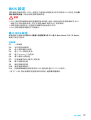
Updating BIOS
Updating BIOS with M-FLASH
Before updating:
Please download the latest BIOS file that matches your motherboard model from MSI
website. And then save the BIOS file into the USB flash drive.
Updating BIOS:
1. Press Del key to enter the BIOS Setup during POST.
2. Insert the USB flash drive that contains the update file into the computer.
3. Select the M-FLASH tab and click on Yes to reboot the system and enter the flash
mode.
4. Select a BIOS file to perform the BIOS update process.
5. After the flashing process is 100% completed, the system will reboot
automatically.
Updating the BIOS with Live Update 6
Before updating:
Make sure the LAN driver is already installed and the Internet connection is set
properly.
Updating BIOS:
1. Install and launch MSI LIVE UPDATE 6.
2. Select BIOS Update.
3. Click on Scan button.
4. Click on Download icon to download and install the latest BIOS file.
5. Click Next and choose In Windows mode. And then click Next and Start to start
updating BIOS.
6. After the flashing process is 100% completed, the system will restart
automatically.

19
BIOS Setup Software Description
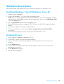
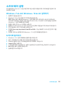
Software Description
Please download and update the latest utilities and drivers at www.msi.com
Installing Windows
®
7 64-bit/ Windows
®
10 64-bit
1. Power on the computer.
2. Insert the Windows
®
7/ 10 disc into your optical drive.
Note: Due to chipset limitation, during the Windows
®
7 installation process, USB
optical drives and USB pen drives are not supported. You can use MSI Smart Tool
to install Windows
®
7.
3. Press the Restart button on the computer case.
4. Press F11 key during the computer POST (Power-On Self Test) to get into Boot
Menu.
5. Select your optical drive from the Boot Menu.
6. Press any key when screen shows Press any key to boot from CD or DVD...
message.
7. Follow the instructions on the screen to install Windows
®
7/ 10.
Installing Drivers
1. Start up your computer in Windows
®
7/ 10.
2. Insert MSI
®
Driver Disc into your optical drive.
3. The installer will automatically appear and it will find and list all necessary
drivers.
4. Click Install button.
5. The software installation will then be in progress, after it has finished it will
prompt you to restart.
6. Click OK button to finish.
7. Restart your computer.

20
Software Description
Installing Utilities
Before you install utilities, you must complete drivers installation.
1. Insert MSI
®
Driver Disc into your optical drive.
2. The installer will automatically appear.
3. Click Utilities tab.
4. Select the utilities you want to install.
5. Click Install button.
6. The utilities installation will then be in progress, after it has finished it will
prompt you to restart.
7. Click OK button to finish.
8. Restart your computer.
Seite wird geladen ...
Seite wird geladen ...
Seite wird geladen ...
Seite wird geladen ...
Seite wird geladen ...
Seite wird geladen ...
Seite wird geladen ...
Seite wird geladen ...
Seite wird geladen ...
Seite wird geladen ...
Seite wird geladen ...
Seite wird geladen ...
Seite wird geladen ...
Seite wird geladen ...
Seite wird geladen ...
Seite wird geladen ...
Seite wird geladen ...
Seite wird geladen ...
Seite wird geladen ...
Seite wird geladen ...
Seite wird geladen ...
Seite wird geladen ...
Seite wird geladen ...
Seite wird geladen ...
Seite wird geladen ...
Seite wird geladen ...
Seite wird geladen ...
Seite wird geladen ...
Seite wird geladen ...
Seite wird geladen ...
Seite wird geladen ...
Seite wird geladen ...
Seite wird geladen ...
Seite wird geladen ...
Seite wird geladen ...
Seite wird geladen ...
Seite wird geladen ...
Seite wird geladen ...
Seite wird geladen ...
Seite wird geladen ...
Seite wird geladen ...
Seite wird geladen ...
Seite wird geladen ...
Seite wird geladen ...
Seite wird geladen ...
Seite wird geladen ...
Seite wird geladen ...
Seite wird geladen ...
Seite wird geladen ...
Seite wird geladen ...
Seite wird geladen ...
Seite wird geladen ...
Seite wird geladen ...
Seite wird geladen ...
Seite wird geladen ...
Seite wird geladen ...
Seite wird geladen ...
Seite wird geladen ...
Seite wird geladen ...
Seite wird geladen ...
Seite wird geladen ...
Seite wird geladen ...
Seite wird geladen ...
Seite wird geladen ...
Seite wird geladen ...
Seite wird geladen ...
Seite wird geladen ...
Seite wird geladen ...
Seite wird geladen ...
Seite wird geladen ...
Seite wird geladen ...
Seite wird geladen ...
Seite wird geladen ...
Seite wird geladen ...
Seite wird geladen ...
Seite wird geladen ...
Seite wird geladen ...
Seite wird geladen ...
Seite wird geladen ...
Seite wird geladen ...
Seite wird geladen ...
Seite wird geladen ...
Seite wird geladen ...
Seite wird geladen ...
Seite wird geladen ...
Seite wird geladen ...
Seite wird geladen ...
Seite wird geladen ...
Seite wird geladen ...
Seite wird geladen ...
Seite wird geladen ...
Seite wird geladen ...
Seite wird geladen ...
Seite wird geladen ...
Seite wird geladen ...
Seite wird geladen ...
Seite wird geladen ...
Seite wird geladen ...
Seite wird geladen ...
Seite wird geladen ...
Seite wird geladen ...
Seite wird geladen ...
Seite wird geladen ...
Seite wird geladen ...
Seite wird geladen ...
Seite wird geladen ...
Seite wird geladen ...
Seite wird geladen ...
Seite wird geladen ...
Seite wird geladen ...
Seite wird geladen ...
Seite wird geladen ...
Seite wird geladen ...
Seite wird geladen ...
Seite wird geladen ...
Seite wird geladen ...
Seite wird geladen ...
Seite wird geladen ...
Seite wird geladen ...
Seite wird geladen ...
Seite wird geladen ...
Seite wird geladen ...
Seite wird geladen ...
Seite wird geladen ...
Seite wird geladen ...
Seite wird geladen ...
Seite wird geladen ...
Seite wird geladen ...
Seite wird geladen ...
Seite wird geladen ...
Seite wird geladen ...
Seite wird geladen ...
Seite wird geladen ...
Seite wird geladen ...
Seite wird geladen ...
Seite wird geladen ...
Seite wird geladen ...
Seite wird geladen ...
Seite wird geladen ...
Seite wird geladen ...
Seite wird geladen ...
Seite wird geladen ...
Seite wird geladen ...
Seite wird geladen ...
-
 1
1
-
 2
2
-
 3
3
-
 4
4
-
 5
5
-
 6
6
-
 7
7
-
 8
8
-
 9
9
-
 10
10
-
 11
11
-
 12
12
-
 13
13
-
 14
14
-
 15
15
-
 16
16
-
 17
17
-
 18
18
-
 19
19
-
 20
20
-
 21
21
-
 22
22
-
 23
23
-
 24
24
-
 25
25
-
 26
26
-
 27
27
-
 28
28
-
 29
29
-
 30
30
-
 31
31
-
 32
32
-
 33
33
-
 34
34
-
 35
35
-
 36
36
-
 37
37
-
 38
38
-
 39
39
-
 40
40
-
 41
41
-
 42
42
-
 43
43
-
 44
44
-
 45
45
-
 46
46
-
 47
47
-
 48
48
-
 49
49
-
 50
50
-
 51
51
-
 52
52
-
 53
53
-
 54
54
-
 55
55
-
 56
56
-
 57
57
-
 58
58
-
 59
59
-
 60
60
-
 61
61
-
 62
62
-
 63
63
-
 64
64
-
 65
65
-
 66
66
-
 67
67
-
 68
68
-
 69
69
-
 70
70
-
 71
71
-
 72
72
-
 73
73
-
 74
74
-
 75
75
-
 76
76
-
 77
77
-
 78
78
-
 79
79
-
 80
80
-
 81
81
-
 82
82
-
 83
83
-
 84
84
-
 85
85
-
 86
86
-
 87
87
-
 88
88
-
 89
89
-
 90
90
-
 91
91
-
 92
92
-
 93
93
-
 94
94
-
 95
95
-
 96
96
-
 97
97
-
 98
98
-
 99
99
-
 100
100
-
 101
101
-
 102
102
-
 103
103
-
 104
104
-
 105
105
-
 106
106
-
 107
107
-
 108
108
-
 109
109
-
 110
110
-
 111
111
-
 112
112
-
 113
113
-
 114
114
-
 115
115
-
 116
116
-
 117
117
-
 118
118
-
 119
119
-
 120
120
-
 121
121
-
 122
122
-
 123
123
-
 124
124
-
 125
125
-
 126
126
-
 127
127
-
 128
128
-
 129
129
-
 130
130
-
 131
131
-
 132
132
-
 133
133
-
 134
134
-
 135
135
-
 136
136
-
 137
137
-
 138
138
-
 139
139
-
 140
140
-
 141
141
-
 142
142
-
 143
143
-
 144
144
-
 145
145
-
 146
146
-
 147
147
-
 148
148
-
 149
149
-
 150
150
-
 151
151
-
 152
152
-
 153
153
-
 154
154
-
 155
155
-
 156
156
-
 157
157
-
 158
158
-
 159
159
-
 160
160
-
 161
161
-
 162
162
-
 163
163
-
 164
164


MSI A320M GAMING PRO Benutzerhandbuch
- Kategorie
- Motherboards
- Typ
- Benutzerhandbuch
- Dieses Handbuch eignet sich auch für
in anderen Sprachen
Verwandte Artikel
-
MSI MS-7A39v2.0 Benutzerhandbuch
-
MSI X370 XPOWER GAMING TITANIUM Bedienungsanleitung
-
MSI MS-7A36v1.0 Benutzerhandbuch
-
MSI X370 GAMING M7 ACK Bedienungsanleitung
-
-
MSI H310M Benutzerhandbuch
-
-
-
-