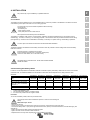
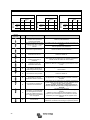
Victron energy Quattro 5k 8k 10k 15k 100-100A 230V (firmware xxxx4xx) Bedienungsanleitung
- Typ
- Bedienungsanleitung

Manual
EN
Handleiding
NL
Manuel
FR
Anleitung
DE
Manual
ES
Användarhandbok
SV
Manuele
IT
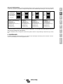
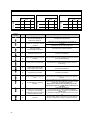
Appendix
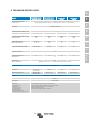
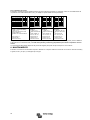
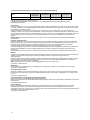
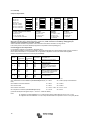
Quattro
(with firmware xxxx400 or higher)
12 | 5000 | 220 – 100|100 – 230V
24 | 5000 | 120 – 100|100 – 230V
48 | 5000 | 70 – 100|100 – 230V
24 | 8000 | 200 – 100|100 – 230V
48 | 8000 | 110 – 100|100 – 230V
48 | 10000 | 140 – 100|100 – 230V
48 | 15000 | 200 – 100|100 – 230V


1
EN NL FR DE ES SV IT Appendix
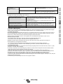
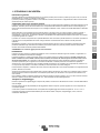
1. SAFETY INSTRUCTIONS
In general
Please read the documentation supplied with this product first, so that you are familiar with the safety signs en directions before
using the product.
This product is designed and tested in accordance with international standards. The equipment should be used for the
designated application only.
WARNING: DANGER OF ELECTRICAL SHOCK
The product is used in combination with a permanent energy source (battery). Even if the equipment is switched off, a
dangerous electrical voltage can occur at the input and/or output terminals. Always switch the AC power off and disconnect the
battery before performing maintenance. In addition discharge the battery terminals or wait 30 minutes.
This appliance is not designed for use by young children or people who cannot read or understand the manual unless they are
under the supervision of a responsible person to ensure that they can use the battery charger safely. Store and use the battery
charger out of the reach of children, and ensure that children cannot play with the charger.
The product contains no internal user-serviceable parts. Do not remove the front panel and do not put the product into
operation unless all panels are fitted. All maintenance should be performed by qualified personnel.
Never use the product at sites where gas or dust explosions could occur. Refer to the specifications provided by the
manufacturer of the battery to ensure that the battery is suitable for use with this product. The battery manufacturer's safety
instructions should always be observed.
WARNING: do not lift heavy objects unassisted.
Installation
Read the installation instructions before commencing installation activities. For electrical work, follow the local national wiring
standard, regulation and this installation instructions.
This product is a safety class I device (supplied with a ground terminal for safety purposes). Its AC input and/or output
terminals must be provided with uninterruptable grounding for safety purposes. An additional grounding point is
located on the outside of the product. If it can be assumed that the grounding protection is damaged, the product should be
taken out of operation and prevented from accidentally being put into operation again; contact qualified maintenance personnel.
Ensure that the connection cables are provided with fuses and circuit breakers. Never replace a protective device by a
component of a different type. Refer to the manual for the correct part.
Check before switching the device on whether the available voltage source conforms to the configuration settings of the product
as described in the manual.
Ensure that the equipment is used under the correct operating conditions. Never operate it in a wet or dusty environment.
Ensure that there is always sufficient free space around the product for ventilation, and that ventilation openings are not
blocked.
Install the product in a heatproof environment. Ensure therefore that there are no chemicals, plastic parts, curtains or other
textiles, etc. in the immediate vicinity of the equipment.
Transport and storage
On storage or transport of the product, ensure that the mains supply and battery leads are disconnected.
No liability can be accepted for damage in transit if the equipment is not transported in its original packaging.
Store the product in a dry environment; the storage temperature should range from –20 °C to 60 °C.
Refer to the battery manufacturer's manual for information on transport, storage, charging, recharging and disposal of the
battery.

2
2. DESCRIPTION
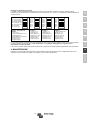
2.1 In general
The basis of the Quattro is an extremely powerful sine inverter, battery charger and automatic switch in a compact casing.
The Quattro features the following additional, often unique characteristics:
Two AC inputs; integrated switch-over system between shore voltage and generating set
The Quattro features two AC inputs (AC-in-1 and AC-in-2) for connecting two independent voltage sources. For example, two
generator sets, or a mains supply and a generator set. The Quattro automatically selects the input where voltage is present.
If voltage is present on both inputs, the Quattro selects the AC-in-1 input, to which normally the generating set is connected.
Two AC outputs
Besides the usual uninterruptable output (AC-out-1), an auxiliary output (AC-out-2) is available that disconnects its load in the
event of battery operation. Example: an electric boiler that is allowed to operate only if the genset is running or shore power is
available.
Automatic and uninterruptible switching
In the event of a supply failure or when the genset is switched off, the Quattro will switch over to inverter operation and take
over the supply of the connected devices. This is done so quickly that operation of computers and other electronic devices is
not disturbed (Uninterruptible Power Supply or UPS functionality). This makes the Quattro highly suitable as an emergency
power system in industrial and telecommunication applications.
Virtually unlimited power thanks to parallel operation
Up to 6 Quattro’s can operate in parallel. Six units 48/10000/140, for example, will provide 54 kW / 60 kVA output power and
840 Amps charging capacity.
Three phase capability
Three units can be configured for three-phase output. But that’s not all: up to 6 sets of three units can be parallel connected to
provide 162 kW / 180 kVA inverter power and more than 2500 A charging capacity.
PowerControl – maximum use of limited shore current
The Quattro can supply a huge charging current. This implies heavy loading of the shore connection or generating set. For both
AC inputs, therefore, a maximum current can be set. The Quattro then takes other power users into account, and only uses
'surplus' current for charging purposes.
- Input AC-in-1, to which usually a generating set is connected, can be set to a fixed maximum with DIP switches, with VE.Net
or with a PC, so that the generating set is never overloaded.
- Input AC-in-2 can also be set to a fixed maximum. In mobile applications (ships, vehicles), however, a variable setting by
means of a Multi Control Panel will usually be selected. In this way the maximum current can be adapted to the available shore
current in an extremely simple manner.
PowerAssist – Extended use of your generating set and shore current: the Quattro “co-supply” feature
The Quattro operates in parallel with the generating set or the shore connection. A current shortfall is automatically
compensated: the Quattro draws extra power from the battery and helps along. A current surplus is used to recharge the
battery.
Three programmable relays
The Quattro is equipped with 3 programmable relays. The relays can be programmed for all kinds of other applications
however, for example as a starter relay for a generating set.
Two programmable analog/digital input/output ports
The Quattro is equipped with 2 analog/digital input/output ports.
These ports can be used for several purposes. One application is communication with the BMS of a lithium-ion battery.
Frequency shift
When solar inverters are connected to the output of a Multi or Quattro, the excess solar energy is used to recharge the
batteries. Once the absorption voltage is reached, the Multi or Quattro will shut down the solar inverter by shifting the output
frequency 1 Hz (from 50 Hz to 51 Hz for example). Once battery voltage has dropped slightly, the frequency returns to normal
and the solar inverters will restart.
Built-in Battery Monitor (optional)
The ideal solution when Multi’s or Quattro’s are part of a hybrid system (diesel generator, inverter/chargers, storage battery,
and alternative energy). The built-in battery monitor can be set to start and stop the generator:
- Start at a preset % discharge level, and/or
- start (with a preset delay) at a preset battery voltage, and/or
- start (with a preset delay) at a preset load level.
- Stop at a preset battery voltage, or
- stop (with a preset delay) after the bulk charge phase has been completed, and/or
- stop (with a preset delay) at a preset load level.

3
EN NL FR DE ES SV IT Appendix
Solar energy
The Quattro is extremely suitable for solar energy applications. It can be used for building autonomous systems as well as
mains-coupled systems.
Emergency power or autonomous operation on mains failure
Houses or buildings provided with solar panels or a combined micro-scale heating and power plant (a power-generating central
heating boiler) or other sustainable energy sources have a potential autonomous energy supply which can be used for
powering essential equipment (central heating pumps, refrigerators, deep freeze units, Internet connections, etc.) during a
power failure. A problem in this regard, however, is that mains-coupled solar panels and/or micro-scale heating and power
plants drop out as soon as the mains supply fails. With a Quattro and batteries, this problem can be solved in a simple manner:
the Quattro can replace the mains supply during a power failure. When the sustainable energy sources produce more power
than necessary, the Quattro will use the surplus to charge the batteries; in the event of a shortfall, the Quattro will supply
additional power from its battery energy resources.
Programmable with DIP switches, VE.Net panel or personal computer
The Quattro is supplied ready for use. Three features are available for changing certain settings if desired:
- The most important settings (including parallel operation of up to three devices and 3-phase operation) can be changed in a
very simple manner, using Quattro DIP switches.
- All settings, with exception of the multi-functional relay, can be changed with a VE.Net panel.
- All settings can be changed with a PC and free of charge software, downloadable from our website www.victronenergy.com
2.2 Battery charger
Adaptive 4-stage charging characteristics: bulk – absorption – float – storage
The microprocessor-driven adaptive battery management system can be adjusted for various types of batteries. The adaptive
function automatically adapts the charging process to battery use.
The right amount of charge: variable absorption time
In the event of slight battery discharge, absorption is kept short to prevent overcharging and excessive gas formation. After
deep discharging, the absorption time is automatically extended in order to fully charge the battery.
Preventing damage due to excessive gassing: the BatterySafe mode
If, in order to quickly charge a battery, a high charge current in combination with a high absorption voltage has been chosen,
damage due to excessive gassing will be prevented by automatically limiting the rate of voltage increase once the gassing
voltage has been reached.
Less maintenance and aging when the battery is not in use: the Storage mode
The Storage mode kicks in whenever the battery has not been subjected to discharge during 24 hours. In the Storage mode
float voltage is reduced to 2,2 V/cell (13,2 V for 12 V battery) to minimise gassing and corrosion of the positive plates. Once a
week the voltage is raised back to the absorption level to “equalize” the battery. This feature prevents stratification of the
electrolyte and sulphation, a major cause of early battery failure.
Two DC outputs for charging two batteries
The main DC terminal can supply the full output current. The second output, intended for charging a starter battery, is limited to
4 A and has a slightly lower output voltage.
Increasing service life of the battery: temperature compensation
The temperature sensor (supplied with the product) serves to reduce charging voltage when battery temperature rises. This is
particularly important for maintenance-free batteries, which could otherwise dry out by overcharging.
Battery voltage sense: the correct charge voltage
Voltage loss due to cable resistance can be compensated by using the voltage sense facility to measure voltage directly on the
DC bus or on the battery terminals.
More on batteries and charging
Our book “Energy Unlimited” offers further information on batteries and battery charging, and is available free of charge on our
website (see www.victronenergy.com -> Support & Downloads -> General Technical Information). For more information on
adaptive charging, please also refer to the General Technical Information our website.
2.3 Self consumption – solar energy storage systems
When the Multi/Quattro is used in a configuration in which it will feed back energy to the grid it is required to enable grid code
compliance by selecting the grid code country setting with the VEConfigure tool.
This way the Multi/Quattro can comply to the local rules.
Once set, a password will be required to disable grid code compliance or change grid code related parameters.
If the local grid code is not supported by the Multi/Quattro an external certified interface device should be used to connect the
Multi/Quattro to the grid.
The Multi/Quattro can also be used as a bidirectional inverter operating parallel to the grid, integrated into a
customer designed system (PLC or other) that takes care of the control-loop and grid measurement, see
http://www.victronenergy.com/live/system_integration:hub4_grid_parallel
Special note for Australian customers: IEC62109.1 certification and CEC approval for off-grid use does NOT imply approval for
grid-interactive installations. Additional certification to IEC 62109.2 and AS 4777.2.2015 are required before grid-interactive
systems can be implemented. Please check Clean Energy Council website for current approvals.

4
3. OPERATION
3.1 “On/Off/Charger Only Switch”
When switched to “on”, the product is fully functional. The inverter will come into operation and the LED “inverter on” will light
up.
An AC voltage connected to the “AC in” terminal will be switched through to the “AC out” terminal, if within specifications. The
inverter will switch off, the “mains on” LED will light up and the charger commences charging. The “bulk”, “absorption” or “float”
LED’s will light up, depending on the charger state.
If the voltage at the “AC-in” terminal is rejected, the inverter will switch on.
When the switch is switched to “charger only”, only the battery charger of the Quattro will operate (if mains voltage is present).
In this mode input voltage also is switched through to the “AC out” terminal.
NOTE: When only the charger function is required, ensure that the switch is switched to “charger only”. This prevents the
inverter from being switched on if the mains voltage is lost, thus preventing your batteries from running flat.
3.2 Remote control
Remote control is possible with a 3-way switch or with a Multi Control panel.
The Multi Control panel has a simple rotary knob with which the maximum current of the AC input can be set: see PowerControl
and PowerAssist in Section 2.
3.3 Equalisation and forced absorption
3.3.1 Equalisation
Traction batteries require regular additional charging. In the equalisation mode, the Quattro will charge with increased voltage
for one hour (1 V above the absorption voltage for a 12 V battery, 2 V for a 24 V battery), and with charging current limited to
1/4 of the set value. The “bulk” and “absorption” LED’s flash intermittently.
Equalisation mode supplies a higher charging voltage than most DC consuming
devices can cope with. These devices must be disconnected before additional
charging takes place.
3.3.2 Forced absorption
Under certain circumstances, it can be desirable to charge the battery for a fixed time at absorption voltage level. In Forced
Absorption mode, the Quattro will charge at the normal absorption voltage level during the set maximum absorption time. The
“absorption” LED lights.
3.3.3 Activating equalisation or forced absorption
The Quattro can be put into both these states from the remote panel as well as with the front panel switch, provided that all
switches (front, remote and panel) are set to “on” and no switches are set to “charger only”.
In order to put the Quattro in this state, the procedure below should be followed.
If the switch is not in the required position after following this procedure, it can be switched over quickly once. This will not
change the charging state.
NOTE: Switching from “on” to “charger only” and back, as described below, must be done quickly. The switch must be toggled
such that the intermediate position is 'skipped', as it were. If the switch remains in the “off” position even for a short time, the
device may be turned off. In that case, the procedure must be restarted at step 1. A certain degree of familiarisation is required
when using the front switch on the Compact in particular. When using the remote panel, this is less critical.
Procedure:
- Check whether all switches (i.e. front switch, remote switch or remote panel switch if present) are in the “on” position.
- Activating equalisation or forced absorption is only meaningful if the normal charging cycle is completed (charger is in 'Float').
- To activate:
a. Switch rapidly from “on” to “charger only” and leave the switch in this position for ½ to 2 seconds.
b. Switch rapidly back from “charger only” to “on” and leave the switch in this position for ½ to 2 seconds.
c. Switch once more rapidly from “on” to “charger only” and leave the switch in this position.
- On the Quattro (and, if connected, on the MultiControl panel) the three LED’s “Bulk”, “Absorption” and “Float” will now flash 5 times.
- Subsequently, the LED’s “Bulk”, “Absorption” and “Float” will each light during 2 seconds.
a. If the switch is set to “on” while the “Bulk” LED lights, the charger will switch to equalisation.
b. If the switch is set to “on” while the “Absorption” LED lights, the charger will switch to forced absorption.
c. If the switch is set to “on” after the three LED sequence has finished, the charger will switch to “Float”.
d. If the switch has not been moved, the Quattro’s will remain in “charger only’ mode and switch to “Float”.

5
EN NL FR DE ES SV IT Appendix
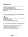
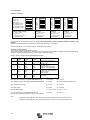
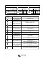
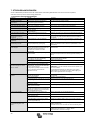
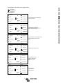
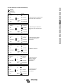
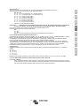
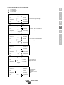
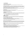
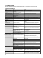
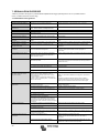
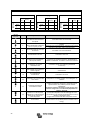
3.4 LED indications and their meaning
LED off
LED flashes
LED lights
Inverter
charger
inverter
The inverter is on, and supplies
power to the load.
mains on
on
inverter on
bulk
overload
off
absorption
low battery
charger
only
float
temperature
charger
inverter
The nominal power of the inverter is
exceeded. The “overload” LED
flashes.
mains on
on
inverter on
bulk
overload
off
absorption
low battery
charger
only
float
temperature
charger
inverter
The inverter is switched off due to
overload or short circuit.
mains on
on
inverter on
bulk
overload
off
absorption
low battery
charger
only
float
temperature
charger
inverter
The battery is almost empty.
mains on
on
inverter on
bulk
overload
off
absorption
low battery
charger
only
float
temperature
charger
inverter
The inverter is switched off due to
low battery voltage.
mains on
on
inverter on
bulk
overload
off
absorption
low battery
charger
only
float
temperature
charger
inverter
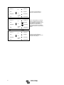
The internal temperature is reaching
a critical level.
mains on
on
inverter on
bulk
overload
off
absorption
low battery
charger
only
float
temperature

6
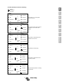
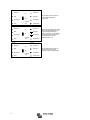
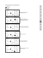
charger
inverter
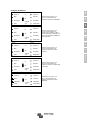
The inverter is switched off due to
excessively high internal
temperature.
mains on
on
inverter on
bulk
overload
off
absorption
low battery
charger
only
float
temperature
charger
inverter
– If the LEDs flash alternately, the
battery almost empty and nominal
power is exceeded.
– If “overload” and “low battery”
flash simultaneously, there is an
excessively high ripple voltage at
the battery connection.
mains on
on
inverter on
bulk
overload
off
absorption
low battery
charger
only
float
temperature
charger
inverter
The inverter is switched off due to
an excessively high ripple voltage
on the battery connection.
mains on
on
inverter on
bulk
overload
off
absorption
low battery
charger
only
float
temperature

7
EN NL FR DE ES SV IT Appendix
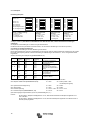
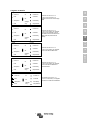
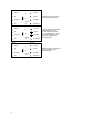
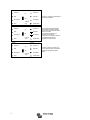
Battery charger
charger
inverter
The AC voltage on AC-in-1 or
AC-in-2 is switched through, and
the charger operates in bulk phase.
mains on
on
inverter on
bulk
overload
off
absorption
low battery
charger
only
float
temperature
charger
inverter
The AC voltage on AC-in-1 or
AC-in-2 is switched through and the
charger operates, but the set
absorption voltage has not yet been
reached (battery protection mode)
mains on
on
inverter on
bulk
overload
off
absorption
low battery
charger
only
float
temperature
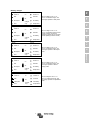
charger
inverter
The AC voltage on AC-in-1 or
AC-in-2 is switched through, and
the charger operates in absorption
phase.
mains on
on
inverter on
bulk
overload
off
absorption
low battery
charger
only
float
temperature
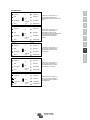
charger
inverter
The AC voltage on AC-in-1 or
AC-in-2 is switched through, and
the charger operates in float or
storage phase.
mains on
on
inverter on
bulk
overload
off
absorption
low battery
charger
only
float
temperature
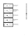
charger
inverter
The AC voltage on AC-in-1 or
AC-in-2 is switched through, and
the charger operates in equalisation
mode.
mains on
on
inverter on
bulk
overload
off
absorption
low battery
charger
only
float
temperature

8
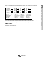
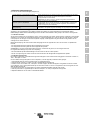
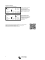
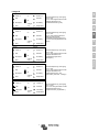
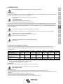
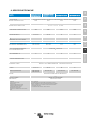
Special indications
Set with limited input current
charger
inverter
Occurs only if PowerAssist is
disabled.
The AC voltage on AC1-in-1 or
AC-in-2 is switched through. The
AC-input current is equal to the
load current. The charger is down-
controlled to 0A.
mains on
on
inverter on
bulk
overload
off
absorption
low battery
charger
only
float
temperature
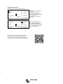
Set to supply additional current
charger
inverter
The AC voltage on AC-in-1 or
AC-in-2 is switched through, but the
load demands more current than
the mains can supply. The inverter
is now switched on to supply
additional current.
mains on
on
inverter on
bulk
overload
off
absorption
low battery
charger
only
float
temperature
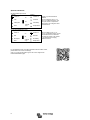
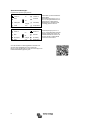
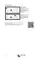
For the latest and most up to date information about the blink codes,
please refer to the Victron Toolkit app.
Click on or scan the QR code to get to the Victron Support and
Downloads/Software page.

9
EN NL FR DE ES SV IT Appendix
4. INSTALLATION
This product may only be installed by a qualified electrician.
4.1 Location
The Quattro should be installed in a dry, well-ventilated location, as close as possible to the batteries. The device should be
surrounded by a free space of at least 10 cm for cooling purposes.
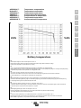
An excessively high environmental temperature has the following
consequences:
- shorter lifecycle
- lower charging current
- lower peak power or full inverter shut off.
Never place the device directly above the batteries.
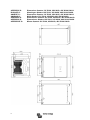
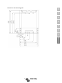
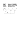
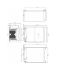
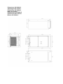
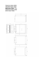
The Quattro is suitable for wall mounting. A solid surface, suitable for the weight and dimensions of the product must be
available (e.g., concrete, or masonry). For mounting purposes, a hook and two holes are provided at the back of the casing
(see appendix G). The device can be fitted either horizontally or vertically. For optimal cooling, vertical fitting is preferred.
The inner part of the device should remain well accessible after installation.
The distance between the Quattro and the battery should be as short as possible to reduce voltage loss across the battery
leads to a minimum.
Install the product in a heatproof environment.
Ensure therefore that there are no chemicals, plastic parts,
curtains or other textiles, etc. in the direct vicinity.
The Quattro has no internal DC fuse. The DC fuse should be installed
outside the Quattro.
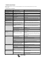
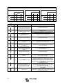
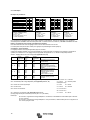
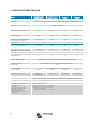
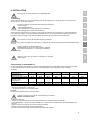
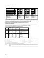
4.2 Connecting the battery cables
In order to use the full potential of the Quattro, batteries of sufficient capacity and battery cables with the correct cross-section
should be used. To isolate the batteries from the Quattro a disconnect device adequate for the rating should be used.
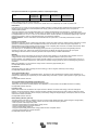
See table:
12/5000/200
24/5000/120
48/5000/70
24/8000/200
48/8000/110
48/10000/140
48/15000/200
Recommended battery capacity
(Ah) 800–2400 400–1400 200–800 400–1400 200–800 250 - 1000 400 - 1500
Recommended DC fuse
800 A
400 A
200 A
500 A
300 A
400 A
600 A
Recommended cross-section
(mm2) per + and - connection
terminal *, **
0 – 5 m***
2x 120 mm2
2x 50 mm2
1x 70 mm2
2x 70 mm2
2x 50 mm2
2x 50 mm2
2x 95 mm2
5 -10 m***
2x 95 mm2
2x 70 mm2
2x 120 mm2
2x 95 mm2
2x 95 mm2
2x 150 mm2
* Follow local installation rules.
** Do not locate battery cables in a closed conduit.
*** “2x” means two positive and two negative cables.
Procedure
To connect the battery cables, follow the procedure below:
Use a torque wrench with insulated box spanner in order to avoid shorting the
battery.
Maximum torque: 14 Nm
- Remove the DC fuse.
- Loosen the four lower front panel screws at the front of the unit, and remove the lower front panel.
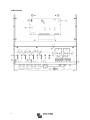
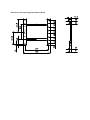
- Connect the battery leads: + (red) to the right-hand terminal and - (black) to the left-hand terminal, use M8 cable lugs. (see
appendix A).
- Tighten the connections after mounting the fastening parts.
- Tighten the nuts well for minimal contact resistance.
- Replace the DC fuse only after completing the whole installation procedure.

10
4.3 Connecting AC cables
The Quattro is a safety class I product (supplied with an ground terminal for safety
purposes), only a TN-S grounding system is allowed). Its AC input and/or output
terminals and/or grounding point on the outside of the product must be
provided with an uninterruptable grounding point for safety purposes. See
the following instructions in this regard.
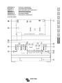
The Quattro is provided with a ground relay (see appendix) that automatically
connects the N output to the casing if no external AC supply is available. If
an external AC supply is provided, the ground relay will open before the input
safety relay closes (relay H in appendix B). This ensures the correct operation of
an earth leakage circuit breaker that is connected to the output.
- In a fixed installation, an uninterruptable grounding can be secured by means of
the grounding wire of the AC input. Otherwise the casing must be grounded.
- In a mobile installation (for example, with a shore current plug), interrupting the
shore connection will simultaneously disconnect the grounding connection. In that
case, the casing must be connected to the chassis (of the vehicle) or to the hull or
grounding plate (of the boat).
- For all AC connections use M6 cable lugs.
- In general, the connection described above to shore connection grounding is not
recommended for boats because of galvanic corrosion. The solution to this is
using an isolating transformer.
The inverter does incorporate a mains frequency isolating transformer. This precludes the possibility of DC current at any AC
port. Therefore type A RCD’s can be used. The RCD must comply to IEC 61008-1 or IEC 61009-1 or to AS/NZS 61800.1 and
AS/NZS 61009.1
AC-in-1 (see appendix A, maximum torque: 7 Nm)
If AC voltage is present on these terminals, the Quattro will use this connection. Generally a generator will be connected to AC-
in-1. An appropriate and readily accessible disconnect device shall be incorporated in the fixed wiring
The AC-in-1 input must be protected by a fuse or magnetic circuit breaker rated at 100 A or less, and cable cross-
section must be sized accordingly. If the input AC supply is rated at a lower value, the fuse or magnetic circuit breaker
should be down sized accordingly.
AC-in-2 (see appendix A, maximum torque: 7 Nm)
If AC voltage is present on these terminals, the Quattro will use this connection, unless voltage is also present on
AC-in-1. The Quattro will then automatically select AC-in-1. Generally the mains supply or shore voltage will be connected
to AC-in-2.
The AC-in-2 input must be protected by a fuse or magnetic circuit breaker rated at 100 A or less, and cable cross-
section must be sized accordingly. If the input AC supply is rated at a lower value, the fuse or magnetic circuit breaker
should be down sized accordingly.
Note: The Quattro may not start when AC is present only on AC-in-2, and DC battery voltage is 10 % or more below
nominal (less than 11 Volt in case of a 12 Volt battery).
Solution: connect AC power to AC-in-1, or recharge the battery.
AC-out-1 (see appendix A, maximum torque: 7 Nm)
The AC output cable can be connected directly to the terminal block “AC-out”.
With its PowerAssist feature the Quattro can add up to 5, 8, 10 or 15 kVA (forexample 10.000 / 230 = 43 A) to the output during
periods of peak power requirement.
Together with a maximum input current of 100 A this means that the output can supply up to 100 + 21 = 121 A (5 kVA models),
100 + 35 = 135 A (8 kVA models), 100 + 43 = 143 A (10 kVA model) and 100 + 65 = 165 A (15 kVA model).
An earth leakage circuit breaker and a fuse or circuit breaker rated to support the expected load must be included in
series with the output, and cable cross-section must be sized accordingly. The maximum rating of the fuse or circuit
breaker is 125 A (5 kVA models), 135 A (8 kVA), 143 A (10 kVA) resp. 165 A (15 kVA).
AC-out-2 (see appendix A, maximum torque: 7 Nm)
A second output is available that disconnects its load in the event of battery operation. On these terminals, equipment is
connected that should operate only if AC voltage is available on AC-in-1 or AC-in-2, e.g. an electric boiler or an air
conditioner. The load on AC-out-2 is disconnected immediately when the Quattro switches to battery operation. After AC power
becomes available on AC-in-1 or AC-in-2, the load on AC-out-2 will be reconnected with a delay of approximately 2 minutes.
This to allow a genset to stabilise.
AC-out-2 can support loads of up to 50 A. An earth leakage circuit breaker and fuse rated at max. 50 A must be connected in
series with AC-out-2.
Procedure
Use three-core cable. The connection terminals are clearly encoded:
PE: earth
N: neutral conductor
L: phase/live conductor

11
EN NL FR DE ES SV IT Appendix
4.4 Connection options
4.4.1 Starter battery (connection terminal E, see appendix A)
The Quattro has a connection for charging a starter battery. Output current is limited to 4 A.
(not available on 48 V models)
4.4.2 Voltage sense (connection terminal E, see appendix A)
For compensating possible cable losses during charging, two sense wires can be connected with which the voltage direct on
the battery or on the positive and negative distribution points can be measured. Use at least wire with a cross-section of
0,75 mm2.
During battery charging, the Quattro will compensate the voltage drop over the DC cables to a maximum of 1 Volt (i.e. 1 V over
the positive connection and 1 V over the negative connection). If the voltage drop threatens to become larger than 1 V, the
charging current is limited in such a way that the voltage drop remains limited to 1 V.
4.4.3 Temperature sensor (connection terminal E, see appendix A)
For temperature-compensated charging, the temperature sensor (supplied with the Quattro) can be connected. The sensor is
isolated and must be fitted to the negative terminal of the battery.
4.4.4 Remote control
The Quattro can be remotely controlled in two ways:
- With an external switch (connection terminal H, see appendix A). Operates only if the switch on the Quattro is set to “on”.
- With a remote control panel (connected to one of the two RJ48 sockets B, see appendix A). Operates only if the switch on the
Quattro is set to “on”.
Using the remote control panel, only the current limit for AC-in-2 can be set (in regard to PowerControl and PowerAssist).
The current limit for AC-in-1 can be set with DIP switches or by means of software.
Only one remote control can be connected, i.e. either a switch or a remote control panel.
4.4.5. Programmable relays (connection terminal I and E (K1 and K2), see appendix A
The Quattro is equipped with 3 programmable relays. The relay that controls terminal I is set as an alarm relay (default setting).
The relays can be programmed for all kinds of other applications, for example to start a generator (VEConfigure software
needed).
4.4.6 Auxiliary AC output (AC-out-2)
Besides the usual uninterruptable output (AC-out-1), a second output (AC-out-2) is available that disconnects its load in the
event of battery operation. Example: an electric boiler or air conditioner that is allowed to operate only if the genset is running or
shore power is available.
In case of battery operation, AC-out-2 is switched off immediately. After the AC supply has become available, AC-out-2 is
reconnected with a delay of 2 minutes, this allow a genset to stabilise prior to connecting a heavy load.
4.4.7 Connecting Quattro’s in parallel (see appendix C)
The Quattro can be connected in parallel with several identical devices. To this end, a connection is established between the
devices by means of standard RJ45 UTP cables. The system (one or more Quattro’s plus optional control panel) will require
subsequent configuration (see Section 5).
In the event of connecting Quattro units in parallel, the following requirements must be met:
- A maximum of 6 units connected in parallel.
- Only identical devices with the same power ratings may be connected in parallel.
- Battery capacity should be sufficient.
- The DC connection cables to the devices must be of equal length and cross-section.
- If a positive and a negative DC distribution point is used, the cross-section of the connection between the batteries and the
DC distribution point must at least equal the sum of the required cross-sections of the connections between the distribution
point and the Quattro units.
- Place the Quattro units close to each other, but allow at least 10 cm for ventilation purposes under, above and beside the
units.
- UTP cables must be connected directly from one unit to the other (and to the remote panel). Connection/splitter boxes are not
permitted.
- A battery-temperature sensor need only be connected to one unit in the system. If the temperature of several batteries is to be
measured, you can also connect the sensors of other Quattro units in the system (with a maximum of one sensor per Quattro).
Temperature compensation during battery charging responds to the sensor indicating the highest temperature.
- Voltage sensing must be connected to the master (see Section 5.5.1.4).
- Only one remote control means (panel or switch) can be connected to the system.
4.4.8 Three-phase configuration (see appendix C)
Quattro’s can also be used in 3-phase wye (Y) configuration. To this end, a connection between the devices is made by means
of standard RJ45 UTP cables (the same as for parallel operation). The system (Quattro’s plus an optional control panel) will
require subsequent configuration (see Section 5).
Pre-requisites: see Section 4.4.7.
Note: the Quattro is not suitable for 3-phase delta (Δ) configuration.

12
5. CONFIGURATION
- Settings may only be changed by a qualified electrical engineer.
- Read the instructions thoroughly before implementing changes.
- During setting of the charger, the DC fuse in the battery connections must be
removed.
5.1 Standard settings: ready for use
On delivery, the Quattro is set to standard factory values. In general, these settings are selected for single-unit operation.
Settings, therefore, do not require changing in the event of stand-alone use.
Warning: Possibly, the standard battery charging voltage is not suitable for your batteries! Refer to the manufacturer's
documentation, or to your battery supplier!
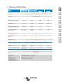
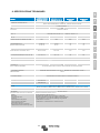
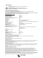
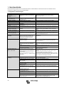
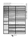
Standard Quattro factory settings
Inverter frequency 50 Hz
Input frequency range 45 - 65 Hz
Input voltage range 180 - 265 VAC
Inverter voltage 230 VAC
Stand-alone / parallel / 3-phase stand-alone
AES (Automatic Economy Switch) off
Ground relay on
Charger on/ off on
Charging characteristics four-stage adaptive with BatterySafe mode
Charging current 75 % of the maximum charging current
Battery type Victron Gel Deep Discharge (also suitable for Victron AGM Deep
Discharge)
Automatic equalisation charging off
Absorption voltage 14.4 / 28.8 / 57.6 V
Absorption time up to 8 hours (depending on bulk time)
Float voltage 13.8 / 27.6 / 55.2 V
Storage voltage 13.2 V (not adjustable)
Repeated absorption time 1 hour
Absorption repeat interval 7 days
Bulk protection on
Generator (AC-in-1) / shore current (AC-in-2) 50 A/16 A (default setting, adjustable current limit for PowerControl and
PowerAssist functions)
UPS feature on
Dynamic current limiter off
WeakAC off
BoostFactor 2
Programmable relay (3x) alarm function
PowerAssist on
Analog/digital input/output ports programmable
Frequency shift off
Built-in Battery Monitor optional
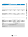
5.2 Explanation of settings
Settings that are not self-explanatory are described briefly below. For further information, please refer to the help files in the
software configuration programs (see Section 5.3).
Inverter frequency
Output frequency if no AC is present at the input.
Adjustability: 50 Hz; 60 Hz
Input frequency range
Input frequency range accepted by the Quattro. The Quattro synchronises within this range with the voltage present on AC-in-1
(priority input) or AC-in-2. Once synchronised, the output frequency will be equal to the input frequency.
Adjustability: 45 – 65 Hz; 45 – 55 Hz; 55 – 65 Hz
Input voltage range
Voltage range accepted by the Quattro. The Quattro synchronises within this range with the voltage present on AC-in-1 (priority
input) or on AC-in-2. After the back feed relay has closed, output voltage will be equal to input voltage.
Adjustability:
Lower limit: 180 – 230 V
Upper limit: 230 – 270 V
Note: the standard lower limit setting of 180 V is intended for connection to a weak mains supply, or to a generator with
unstable AC output. This setting may result in a system shut down when connected to a “brushless, self excited, externally
voltage regulated, synchronous AC generator” (synchronous AVR generator). Most generators rated at 10 kVA or more are
synchronous AVR generators. The shut down is initiated when the generator is stopped and revs down while the AVR
simultaneously “tries” to keep the output voltage of the generator at 230 V.
The solution is to increase the lower limit setting to 210 VAC (the output of AVR generators is generally very stable), or to
disconnect the Quattro from the generator when a generator stop signal is given (with help of an AC contactor installed in
series with the generator).

13
EN NL FR DE ES SV IT Appendix
Inverter voltage
Output voltage of the Quattro in battery operation.
Adjustability: 210 – 245 V
Stand-alone / parallel operation / 2-3 phase setting
Using several devices, it is possible to:
- increase total inverter power (several devices in parallel)
- create a split-phase system (only for Quattro units with 120 V output voltage)
- create a 3-phase system.
To this end, the devices must be mutually connected with RJ45 UTP cables. Standard device settings, however, are such that
each device operates in stand-alone operation. Reconfiguration of the devices is therefore required.
AES (Automatic Economy Switch)
If this setting is turned “on”, the power consumption in no-load operation and with low loads is decreased by approx. 20 %, by
slightly “narrowing” the sinusoidal voltage. Not adjustable with DIP switches. Applicable in stand-alone configuration only.
Search Mode
Instead of the AES mode, the search mode can also be chosen (with help of VEConfigure only).
If search mode is “on”, the power consumption in no-load operation is decreased by approx. 70 %. In this mode the Quattro,
when operating in inverter mode, is switched off in case of no load or very low load, and switches on every two seconds for a
short period. If the output current exceeds a set level, the inverter will continue to operate. If not, the inverter will shut down
again.
The Search Mode “shut down” and “remain on” load levels can be set with VEConfigure.
The standard settings are:
Shut down: 40 Watt (linear load)
Turn on: 100 Watt (linear load)
Not adjustable with DIP switches. Applicable in stand-alone configuration only.
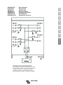
Ground relay (see appendix B)
With this relay (E) the neutral conductor of the AC output is grounded to the casing when the back feed safety relays in the AC-
in-1 and the AC-in-2 inputs are open. This ensures the correct operation of earth leakage circuit breakers in the outputs.
- If a non-grounded output is required during inverter operation, this function must be turned off. (See also Section 4.5)
Not adjustable with DIP switches.
- If required an external ground relay can be connected (for a split-phase system with a separate autotransformer).
See appendix A.
Charging characteristics
The standard setting is “Four-stage adaptive with BatterySafe mode”. See Section 2 for a description.
This is the best charging characteristic. See the help files in the software configuration programs for other features.
“Fixed” mode can be selected with DIP switches.
Battery type
The standard setting is the most suitable for Victron Gel Deep Discharge, Gel Exide A200, and tubular plate stationary batteries
(OPzS). This setting can also be used for many other batteries: e.g. Victron AGM Deep Discharge and other AGM batteries,
and many types of flat-plate open batteries. Four charging voltages can be set with DIP switches.
Automatic equalisation charging
This setting is intended for tubular plate traction batteries. During absorption the voltage limit increases to 2,83 V/cell (34 V for a
24 V battery) once the charge current has tapered down to less than 10 % of the set maximum current.
Not adjustable with DIP switches.
See “tubular plate traction battery charge curve” in VEConfigure.
Absorption time
This depends on the bulk time (adaptive charging characteristic), so that the battery is optimally charged. If the “fixed” charging
characteristic is selected, the absorption time is fixed. For most batteries, a maximum absorption time of eight hours is suitable.
If an extra high absorption voltage is selected for rapid charging (only possible for open, flooded batteries!), four hours is
preferable. With DIP switches, a time of eight or four hours can be set. For the adaptive charging characteristic, this determines
the maximum absorption time.
Storage voltage, Repeated Absorption Time, Absorption Repeat Interval
See Section 2. Not adjustable with DIP switches.
Bulk Protection
When this setting is “on”, the bulk charging time is limited to 10 hours. A longer charging time could indicate a system error (e.g.
a battery cell short-circuit). Not adjustable with DIP switches.

14
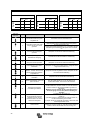
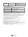
AC input current limit AC-in-1 (generator) and AC-in-2 (shore/grid supply)
Model
12/5000/220
24/5000/120
48/5000/120
24/8000/200
48/8000/110 48/10000/140 48/15000/200
PowerAssist setting range
4 A – 100 A
11 A – 100 A
11 A – 100 A
15 A – 100 A
Factory setting: 50 A for AC1 and 16 A for AC2.
In case of parallel units the minimum and maximum values have to be multiplied by the number of parallel units.
UPS feature
If this setting is “on” and AC on the input fails, the Quattro switches to inverter operation practically without interruption. The
Quattro can then be used as an Uninterruptible Power Supply (UPS) for sensitive equipment such as computers or
communication systems.
The output voltage of some small generating sets is too unstable and distorted for using this setting – the Quattro would
continually switch to inverter operation. For this reason, the setting can be turned off. The Quattro will then respond less quickly
to voltage deviations on AC-in-1 or AC-in-2. The switchover time to inverter operation is consequently slightly longer, but most
equipment (computers, clocks or household equipment) is not adversely impacted.
Recommendation: Turn the UPS feature off if the Quattro fails to synchronise, or continually switches back to inverter
operation.
Dynamic current limiter
Intended for generators, the AC voltage being generated by means of a static inverter (so-called “inverter” generators). In these
generators, rotational speed is down-controlled if the load is low: this reduces noise, fuel consumption and pollution. A
disadvantage is that the output voltage will drop severely or even completely fail in the event of a sudden load increase. More
load can only be supplied after the engine is up to speed.
If this setting is “on”, the Quattro will start supplying extra power at a low generator output level and gradually allow the
generator to supply more, until the set current limit is reached. This allows the generator engine to get up to speed.
This setting is also often used for “classical” generators that respond slowly to sudden load variation.
WeakAC
Strong distortion of the input voltage can result in the charger hardly operating or not operating at all. If WeakAC is set, the
charger will also accept a strongly distorted voltage, at the cost of greater distortion of the input current.
Recommendation: Turn WeakAC on if the charger is hardly charging or not charging at all (which is quite rare!). Also turn on
the dynamic current limiter simultaneously, and reduce the maximum charging current to prevent overloading the generator if
necessary.
Note: when WeakAC is on, the maximum charge current is reduced by approximately 20 %.
Not adjustable with DIP switches.
BoostFactor
Change this setting only after consulting with Victron Energy or with an engineer trained by Victron Energy!
Not adjustable with DIP switches.
Three programmable relays
The Quattro is equipped with 3 programmable relays. The relays can be programmed for all kinds of other applications, for
example as a starter relay for a generating set. The default setting of the relay in postion I (see appendix A, upper right corner)
is “alarm”.
Not adjustable with DIP switches.
Two programmable analog/digital input/output ports
The Quattro is equipped with 2 analog/digital input/output ports.
These ports can be used for several purposes. One application is communication with the BMS of a lithium-ion battery.
Not adjustable with DIP switches.
Frequency shift
When solar inverters are connected to the output of a Multi or Quattro, the excess solar energy is used to recharge the
batteries. Once the absorption voltage is reached, the Multi or Quattro will shut down the solar inverter by shifting the output
frequency 1 Hz (from 50 Hz to 51 Hz for example). Once battery voltage has dropped slightly, the frequency returns to normal
and the solar inverters will restart.
Not adjustable with DIP switches.
Built-in Battery Monitor (optional)
The ideal solution when Multi’s or Quattro’s are part of a hybrid system (diesel generator, inverter/chargers, storage battery,
and alternative energy). The built-in battery monitor can be set to start and stop the generator:
- Start at a preset % discharge level, and/or
- start (with a preset delay) at a preset battery voltage, and/or
- start (with a preset delay) at a preset load level.
- Stop at a preset battery voltage, or
- stop (with a preset delay) after the bulk charge phase has been completed, and/or
- stop (with a preset delay) at a preset load level.
Not adjustable with DIP switches.

15
EN NL FR DE ES SV IT Appendix
5.3 Configuration by computer
All settings can be changed by means of a computer
The most common settings can be changed by means of DIP switches (see Section 5.5).
NOTE:
This manual is intended for products with firmware xxxx400 or higher (with x any number)
The firmware number can be found on the microprocessor, after removing the front panel.
It is possible to update older units, as long as that same 7 digit number starts with either 26 or 27. When it starts with 19 or 20
you have an old microprocessor and it is not possible to update to 400 or higher.
For changing settings with the computer, the following is required:
- VEConfigureII software: can be downloaded free of charge at www.victronenergy.com.
- A RJ45 UTP cable and the MK3-USB interface.
5.3.1 VE.Bus Quick Configure Setup
VE.Bus Quick Configure Setup is a software program with which systems with a maximum of three Quattro units (parallel or
three phase operation) can be configured in a simple manner. VEConfigureII forms part of this program.
The software can be downloaded free of charge at www.victronenergy.com .
For connection to the computer, a RJ45 UTP cable and the MK3-USB interface is required.
5.3.2 VE.Bus System Configurator
For configuring advanced applications and/or systems with four or more Quattro units, VE.Bus System Configurator software
must be used. The software can be downloaded free of charge at www.victronenergy.com . VEConfigureII forms part of this
program.
For connection to the computer, a RJ45 UTP cable and the MK3-USB interface is required.
5.4 Configuration with a VE.Net panel
To this end, a VE.Net panel and the VE.Net to VE.Bus converter is required.
With VE.Net all parameters are accessible, with the exception of the multi-functional relay and the VirtualSwitch.

16
5.5 Configuration with DIP switches
Introduction
A number of settings can be changed using DIP switches (see appendix A, position M).
Note: When changing settings with dipswitches in a parallel or split-phase/3-phase system one should be aware that not all
settings are relevant on all Quattros. This because some settings will be dictated by the Master or Leader.
Some settings are only relevant in the Master/Leader (ie they are not relevant in a slave or in a follower). Other settings are not
relevant for slaves but are relevant for followers.
A note on used terminology:
A system in which more than one Quattro is used to create a single AC phase is called a parallel system. In this case one of the
Quattros will control the whole phase, this one is called the master. The others, called slaves, will just listen to the master to
determine their action.
It is also possible to create more AC phases (split-phase or 3-phase) with 2 or 3 Quattros. In this case the Quattro in Phase L1
is called the Leader. The Quattro in phase L2 (and L3 if available) will generate the same AC frequency but will follow L1 with a
fixed phase shift. These Quattros are called followers.
If more Quattros are used per phase in a split-phase or 3-phase system (for instance 6 Quattros used to build a 3-phase
system with 2 Quattros per phase) then the Leader of the system is also the Master of phase L1. The Followers in phase L2
and L3 will also take the Master role in phase L2 and L3. All others will be slaves.
Setting up parallel or split-phase/3-phase systems should be done by software, see paragraph 5.3.
TIP: If you don’t want to bother about a Quattro being a master/slave/follower then the easiest and most straight forward
way is to set all settings identically on all Quattros.
General procedure:
Turn the Quattro on, preferably unloaded en without AC voltage on the inputs. The Quattro will then operate in inverter mode.
Step 1: Set the DIP switches for:
- the required current limitation of the AC input. (not relevant for slaves)
- limitation of the charging current. (only relevant for Master/Leader)
Press the 'Up' button for 2 seconds (upper button to the right of the DIP switches, see appendix A, position K) to store the
settings after the required values have been set. You can now re-use the DIP switches to apply the remaining settings (step 2).
Step 2: other settings, set the dipswitches for:
- Charge voltages (only relevant for Master/Leader)
- Absorption time (only relevant for Master/Leader)
- Adaptive charging (only relevant for Master/Leader)
- Dynamic current limiter (not relevant for slaves)
- UPS function (not relevant for slaves)
- converter voltage (not relevant for slaves)
- converter frequency (only relevant for Master/Leader)
Press the “Down” button for 2 seconds (lower button to the right of the DIP switches) to store the settings after the dipswitches
have been set in the correct position. You can now leave the DIP switches in the selected positions, so that the “other settings”
can always be recovered.
Remark:
- The DIP switch functions are described in 'top to bottom' order. Since the uppermost DIP switch has the highest number (8),
descriptions start with the switch numbered 8.
Detailed instruction:
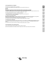
5.5.1 Step 1
5.5.1.1 Current limitation AC inputs (default: AC-in-1: 50 A, AC-in-2: 16 A)
If the current demand (Quattro load + battery charger) threatens to exceed the set current, the Quattro will first reduce its
charging current (PowerControl), and subsequently supply additional power from the battery (PowerAssist), if needed.
The AC-in-1 current limit (the generator) can be set to eight different values by means of DIP switches.
The AC-in-2 current limit can be set to two different values by means of DIP switches. With a Multi Control Panel, a variable
current limit can be set for the AC-in-2 input.

17
EN NL FR DE ES SV IT Appendix
Procedure
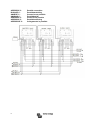
AC-in-1 can be set using DIP switches ds8, ds7 and ds6 (default setting: 50A).
Procedure: set the DIP switches to the required value:
ds8 ds7 ds6
off off off = 6,3 A (PowerAssist 11 A, PowerControl 6 A)
off off on = 10 A (PowerAssist 11 A, PowerControl 10 A)
off on off = 12 A (2.8 kVA at 230 V)
off on on = 16 A (3.7 kVA at 230 V)
on off off = 20 A (4.6 kVA at 230 V)
on off on = 25 A (5,7 kVA at 230 V)
on on off = 30 A (6,9 kVA at 230 V)
on on on = 50 A (11,5 kVA at 230 V)
More than 50 A: with VEConfigure software
Remark: Manufacturer-specified continuous power ratings for small generators are sometimes inclined to be rather
optimistic. In that case, the current limit should be set to a much lower value than would otherwise be
required on the basis of manufacturer-specified data.
AC-in-2 can be set in two steps using DIP switch ds5 (default setting: 16 A).
Procedure: set ds5 to the required value:
ds5
off = 16 A
on = 30 A
More than 30 A: with VEConfigure software or Digital Multi Control Panel
5.5.1.2 Charge current limitation (default setting 75 %)
For maximum battery life, a charge current of 10 % to 20 % of the capacity in Ah should be applied.
Example: optimal charge current of a 24 V/500 Ah battery bank: 50 A to 100 A.
The temperature sensor supplied automatically adjusts the charging voltage to the battery temperature.
If faster charging – and a subsequent higher current – is required:
- the temperature sensor supplied should be fitted to the battery, since fast charging can lead to a considerable temperature
rise of the battery bank. The charging voltage is adapted to the higher temperature (i.e. lowered) by means of the temperature
sensor.
- the bulk charging time will sometimes be so short that a fixed absorption time would be more satisfactory (“fixed” absorption
time, see ds5, step 2).
Procedure
The battery charging current can be set in four steps, using DIP switches ds4 and ds3 (default setting: 75 %).
ds4 ds3
off off = 25 %
off on = 50 %
on off = 75 %
on on = 100 %
Note: when WeakAC is on, the maximum charge current is reduced from 100 % to approximately 80 %.
5.5.1.3 DIP switches ds2 and ds1 are not used during step 1.
IMPORTANT NOTE:
If the last 3 digits of the Multi firmware is in the 100 range (so the firmware number is xxxx1xx (with x any numer))
then ds1 & ds2 are used to set a Multi in stand-alone, parallel or three-phase. Please consult the appropriate manual.

18
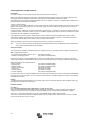
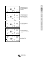
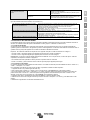
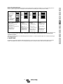
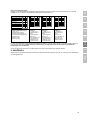
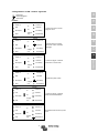
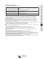
5.5.1.4 Examples
examples of settings:
To store the settings after the required values have been set: press the “Up” button for 2 seconds (upper button to the right of
the DIP switches, see appendix A, position K). The overload and low-battery LED’s will flash to indicate acceptance of the
settings.
We recommend making a note of the settings, and filing this information in a safe place.
The DIP switches can now be used to apply the remaining settings (step 2).
5.5.2 Step 2: Other settings
The remaining settings are not relevant for slaves.
Some of the remaining settings are not relevant for followers (L2, L3). These settings are imposed on the whole system by the
leader L1. If a setting is irrelevant for L2, L3 devices, this is mentioned explicitly.
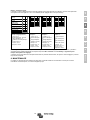
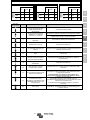
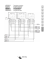
ds8-ds7: Setting charging voltages (not relevant for L2, L3)
ds8-ds7
Absorption
voltage
Float
voltage
Storage
voltage
Suitable for
off off
14.1
28.2
56.4
13.8
27.6
55.2
13.2
26.4
52.8
Gel Victron Long Life (OPzV)
Gel Exide A600 (OPzV)
Gel MK battery
off on
14.4
28.8
57.6
13.8
27.6
55.2
13.2
26.4
52.8
Gel Victron Deep Discharge
Gel Exide A200
AGM Victron Deep Discharge
Stationary tubular plate (OPzS)
on off
14.7
29.4
58.8
13.8
27.6
55.2
13.2
26.4
52.8
AGM Victron Deep Discharge
Tubular plate (OPzS) batteries in
semi-float mode
AGM spiral cell
on on
15.0
30.0
60.0
13.8
27.6
55.2
13.2
26.4
52.8
Tubular plate (OPzS) batteries in
cyclic mode
ds6: absorption time 8 or 4 hours (not relevant for L2, L3) on = 8 hours off = 4 hours
ds5: adaptive charging characteristic (not relevant for L2, L3) on = active off = inactive (fixed absorption time)
ds4: dynamic current limiter on = active off = inactive
ds3: UPS function on = active off = inactive
ds2: converter voltage on = 230 V / 120 V off = 240 V / 115 V
ds1: converter frequency (not relevant for L2, L3) on = 50 Hz off = 60 Hz
(the wide input frequency range (45-55 Hz) is 'on' by default)
Note:
- If “adaptive charging algorithm” is on, ds6 sets the maximum absorption time to 8 hours or 4 hours.
- If “adaptive charging algorithm” is off, the absorption time is set to 8 hours or 4 hours (fixed) by ds6.
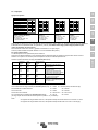
DS-8 AC-in-1
on
DS-7 AC-in-1
on
DS-6 AC-in-1
on
DS-5 AC-in-2
on
DS-4 Charging current
on
DS-3 Charging current
off
DS-2 Stand-alone mode
off
DS-1 Stand-alone mode
off
DS-8
on
DS-7
on
DS-6
on
DS-5
off
DS-4
on
DS-3
on
DS-2
off
DS-1
off
DS-8
off
DS-7
on
DS-6
on
DS-5
off
DS-4
on
DS-3
on
DS-2
off
DS-1
off
DS-8
on
DS-7
on
DS-6
off
DS-5
on
DS-4
off
DS-3
on
DS-2
off
DS-1
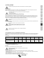
off
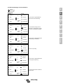
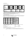
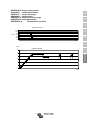
Step1, stand-alone
Example 1 (factory setting):
8, 7, 6 AC-in-1: 50 A
5 AC-in-2: 30 A
4, 3 Charging current: 75 %
2, 1 Stand-alone mode
Step1, stand-alone
Example 2:
8, 7, 6 AC-in-1: 50 A
5 AC-in-2: 16 A
4, 3 Charge: 100 %
2, 1 Stand-alone
Step1, stand-alone
Example 3:
8, 7, 6 AC-in-1: 16 A
5 AC-in-2: 16 A
4, 3 Charge: 100 %
2, 1 Stand-alone
Step1, stand-alone
Example 4:
8, 7, 6 AC-in-1: 30 A
5 AC-in-2: 30 A
4, 3 Charge: 50 %
2, 1 Stand-alone
Seite wird geladen ...
Seite wird geladen ...
Seite wird geladen ...
Seite wird geladen ...
Seite wird geladen ...
Seite wird geladen ...
Seite wird geladen ...
Seite wird geladen ...
Seite wird geladen ...
Seite wird geladen ...
Seite wird geladen ...
Seite wird geladen ...
Seite wird geladen ...
Seite wird geladen ...
Seite wird geladen ...
Seite wird geladen ...
Seite wird geladen ...
Seite wird geladen ...
Seite wird geladen ...
Seite wird geladen ...
Seite wird geladen ...
Seite wird geladen ...
Seite wird geladen ...
Seite wird geladen ...
Seite wird geladen ...
Seite wird geladen ...
Seite wird geladen ...
Seite wird geladen ...
Seite wird geladen ...
Seite wird geladen ...
Seite wird geladen ...
Seite wird geladen ...
Seite wird geladen ...
Seite wird geladen ...
Seite wird geladen ...
Seite wird geladen ...
Seite wird geladen ...
Seite wird geladen ...
Seite wird geladen ...
Seite wird geladen ...
Seite wird geladen ...
Seite wird geladen ...
Seite wird geladen ...
Seite wird geladen ...
Seite wird geladen ...
Seite wird geladen ...
Seite wird geladen ...
Seite wird geladen ...
Seite wird geladen ...
Seite wird geladen ...
Seite wird geladen ...
Seite wird geladen ...
Seite wird geladen ...
Seite wird geladen ...
Seite wird geladen ...
Seite wird geladen ...
Seite wird geladen ...
Seite wird geladen ...
Seite wird geladen ...
Seite wird geladen ...
Seite wird geladen ...
Seite wird geladen ...
Seite wird geladen ...
Seite wird geladen ...
Seite wird geladen ...
Seite wird geladen ...
Seite wird geladen ...
Seite wird geladen ...
Seite wird geladen ...
Seite wird geladen ...
Seite wird geladen ...
Seite wird geladen ...
Seite wird geladen ...
Seite wird geladen ...
Seite wird geladen ...
Seite wird geladen ...
Seite wird geladen ...
Seite wird geladen ...
Seite wird geladen ...
Seite wird geladen ...
Seite wird geladen ...
Seite wird geladen ...
Seite wird geladen ...
Seite wird geladen ...
Seite wird geladen ...
Seite wird geladen ...
Seite wird geladen ...
Seite wird geladen ...
Seite wird geladen ...
Seite wird geladen ...
Seite wird geladen ...
Seite wird geladen ...
Seite wird geladen ...
Seite wird geladen ...
Seite wird geladen ...
Seite wird geladen ...
Seite wird geladen ...
Seite wird geladen ...
Seite wird geladen ...
Seite wird geladen ...
Seite wird geladen ...
Seite wird geladen ...
Seite wird geladen ...
Seite wird geladen ...
Seite wird geladen ...
Seite wird geladen ...
Seite wird geladen ...
Seite wird geladen ...
Seite wird geladen ...
Seite wird geladen ...
Seite wird geladen ...
Seite wird geladen ...
Seite wird geladen ...
Seite wird geladen ...
Seite wird geladen ...
Seite wird geladen ...
Seite wird geladen ...
Seite wird geladen ...
Seite wird geladen ...
Seite wird geladen ...
Seite wird geladen ...
Seite wird geladen ...
Seite wird geladen ...
Seite wird geladen ...
Seite wird geladen ...
Seite wird geladen ...
Seite wird geladen ...
Seite wird geladen ...
Seite wird geladen ...
Seite wird geladen ...
Seite wird geladen ...
Seite wird geladen ...
Seite wird geladen ...
Seite wird geladen ...
Seite wird geladen ...
Seite wird geladen ...
Seite wird geladen ...
Seite wird geladen ...
Seite wird geladen ...
Seite wird geladen ...
Seite wird geladen ...
Seite wird geladen ...
Seite wird geladen ...
Seite wird geladen ...
Seite wird geladen ...
Seite wird geladen ...
Seite wird geladen ...
Seite wird geladen ...
Seite wird geladen ...
Seite wird geladen ...
Seite wird geladen ...
Seite wird geladen ...
Seite wird geladen ...
Seite wird geladen ...
Seite wird geladen ...
Seite wird geladen ...
Seite wird geladen ...
Seite wird geladen ...
Seite wird geladen ...
Seite wird geladen ...
Seite wird geladen ...
Seite wird geladen ...
Seite wird geladen ...
Seite wird geladen ...
Seite wird geladen ...
Seite wird geladen ...
Seite wird geladen ...
Seite wird geladen ...
Seite wird geladen ...
Seite wird geladen ...
Seite wird geladen ...
Seite wird geladen ...
-
 1
1
-
 2
2
-
 3
3
-
 4
4
-
 5
5
-
 6
6
-
 7
7
-
 8
8
-
 9
9
-
 10
10
-
 11
11
-
 12
12
-
 13
13
-
 14
14
-
 15
15
-
 16
16
-
 17
17
-
 18
18
-
 19
19
-
 20
20
-
 21
21
-
 22
22
-
 23
23
-
 24
24
-
 25
25
-
 26
26
-
 27
27
-
 28
28
-
 29
29
-
 30
30
-
 31
31
-
 32
32
-
 33
33
-
 34
34
-
 35
35
-
 36
36
-
 37
37
-
 38
38
-
 39
39
-
 40
40
-
 41
41
-
 42
42
-
 43
43
-
 44
44
-
 45
45
-
 46
46
-
 47
47
-
 48
48
-
 49
49
-
 50
50
-
 51
51
-
 52
52
-
 53
53
-
 54
54
-
 55
55
-
 56
56
-
 57
57
-
 58
58
-
 59
59
-
 60
60
-
 61
61
-
 62
62
-
 63
63
-
 64
64
-
 65
65
-
 66
66
-
 67
67
-
 68
68
-
 69
69
-
 70
70
-
 71
71
-
 72
72
-
 73
73
-
 74
74
-
 75
75
-
 76
76
-
 77
77
-
 78
78
-
 79
79
-
 80
80
-
 81
81
-
 82
82
-
 83
83
-
 84
84
-
 85
85
-
 86
86
-
 87
87
-
 88
88
-
 89
89
-
 90
90
-
 91
91
-
 92
92
-
 93
93
-
 94
94
-
 95
95
-
 96
96
-
 97
97
-
 98
98
-
 99
99
-
 100
100
-
 101
101
-
 102
102
-
 103
103
-
 104
104
-
 105
105
-
 106
106
-
 107
107
-
 108
108
-
 109
109
-
 110
110
-
 111
111
-
 112
112
-
 113
113
-
 114
114
-
 115
115
-
 116
116
-
 117
117
-
 118
118
-
 119
119
-
 120
120
-
 121
121
-
 122
122
-
 123
123
-
 124
124
-
 125
125
-
 126
126
-
 127
127
-
 128
128
-
 129
129
-
 130
130
-
 131
131
-
 132
132
-
 133
133
-
 134
134
-
 135
135
-
 136
136
-
 137
137
-
 138
138
-
 139
139
-
 140
140
-
 141
141
-
 142
142
-
 143
143
-
 144
144
-
 145
145
-
 146
146
-
 147
147
-
 148
148
-
 149
149
-
 150
150
-
 151
151
-
 152
152
-
 153
153
-
 154
154
-
 155
155
-
 156
156
-
 157
157
-
 158
158
-
 159
159
-
 160
160
-
 161
161
-
 162
162
-
 163
163
-
 164
164
-
 165
165
-
 166
166
-
 167
167
-
 168
168
-
 169
169
-
 170
170
-
 171
171
-
 172
172
-
 173
173
-
 174
174
-
 175
175
-
 176
176
-
 177
177
-
 178
178
-
 179
179
-
 180
180
-
 181
181
-
 182
182
-
 183
183
-
 184
184
-
 185
185
-
 186
186
-
 187
187
-
 188
188
-
 189
189
-
 190
190
-
 191
191
-
 192
192


Victron energy Quattro 5k 8k 10k 15k 100-100A 230V (firmware xxxx4xx) Bedienungsanleitung
- Typ
- Bedienungsanleitung
in anderen Sprachen
- français: Victron energy Quattro 5k 8k 10k 15k 100-100A 230V (firmware xxxx4xx) Le manuel du propriétaire
- español: Victron energy Quattro 5k 8k 10k 15k 100-100A 230V (firmware xxxx4xx) El manual del propietario
- italiano: Victron energy Quattro 5k 8k 10k 15k 100-100A 230V (firmware xxxx4xx) Manuale del proprietario
- Nederlands: Victron energy Quattro 5k 8k 10k 15k 100-100A 230V (firmware xxxx4xx) de handleiding
Verwandte Artikel
-
Victron energy Quattro 5k 8k 10k 15k 100-100A 230V (firmware xxxx4xx) Bedienungsanleitung
-
-
-
-
-
-
-