ECO-WORTHY ECO-WORTHY DC24V Pure Sine Wave Off Grid Inverter Benutzerhandbuch
- Typ
- Benutzerhandbuch

ECO-WORTHY
3000W 24V
PURE SINE WAVE
OFF-GRID INVERTER
(USER MANUAL)
Tel E-mail:customer.service@eco-worthy.com Web:www.eco-worthy.com
+44 20 7570 0328(EU)
1-866-939-8222(US)

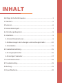
Contents
Important Safety Instructions
1 Overview
2 Appearance
3 Naming rule
4 Connection diagram
5 Installation
5.1 Attentions
5.2 Wire size and circuit breaker
5.3 Mounting
6 Parameters setting
6.1 Power Saving Mode
6.2 Other parameters
7 Protections
8 Troubleshooting
9 Maintenance
10 Specifications
...........................................................1
........................................................................................5
...................................................................................6
...................................................................................7
.......................................................................9
......................................................................................9
................................................................................9
................................................10
...............................................................................11
......................................................................15
..............................................................15
..................................................................17
...................................................................................19
...........................................................................21
................................................................................21
.............................................................................22

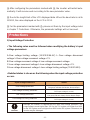
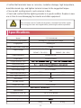
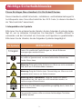
Important Safety Instructions
Please reserve this manual for future review.
This manual contains instructions on the safety, installation, and operation of the
ECO series high-frequency pure sine wave inverter ("inverter" as referred to in this
manual).
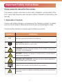
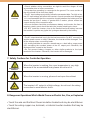
1. Explanation of Symbols
Please read related literature accompanying the following symbols to enable
users to use the product efficiently and ensure personal and property safety.
Please read the literature accompanying the following symbols.
Symbols Definition
TIP Indicates any practical advice for reference
IMPORTANT: Indicates a critical tip during the operation, if ignored,
may cause the device to run in error.
CAUTION: Indicates potential hazards. If not avoided, it may cause
the device to be damaged.
WARNING: Indicates the danger of electric shock. If not avoided, it
would cause casualties.
WARNING HOT SURFACE: Indicates the risk of high temperature,
if not avoided, would cause scalds.
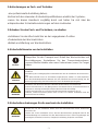
Read the user manual carefully before any operation.
The entire system should be installed by professional and technical
personnel.
WARNING

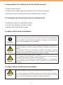
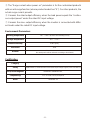
2. Requirements for Professional and Technical Personnel
• Professionally trained
• Familiar with related safety specifications for the electrical system;
• Read this manual carefully and master related safety cautions.
3. Professional and Technical Personnel is Allowed to do
• Install the inverter to a specified location.
• Conduct trial operations for the inverter.
• Operate and maintain the inverter.
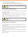
4. Safety Cautions Before Installation
5. Safety Cautions for Mechanical Installation
When you receive the inverter, check whether there is any damage in
transportation. Contact the transportation company, our local distrib-
utor, or our company for any problem.
•
When placing or moving the inverter, follow the instructions in the manual.
•
When installing the inverter, evaluate whether the operation area exists arc
danger.
•
The inverter needs to be connected to a battery. The battery's minimum
capacity (Ah) is recommended to be five times the current that equals the
inverter's rated output power divided by the battery's voltage.
•
Keep the inverter out of the reach of children.
•
This inverter is an off-grid type. It is strictly prohibited to connect the inverter
to the grid. Otherwise, the inverter will be damaged.
•
This inverter is only allowed for stand-alone operation. It is prohibited to
connect multiple units in parallel or series. Otherwise, the inverter will be
damaged.
IMPORTANT
CAUTION
WARNING
WARNING
•
Before installation, ensure the inverter has no electrical connection.
•
Confirm enough heat dissipation space for the inverter before installation.
Do not install the inverter in a harsh environment such as humid, salt spray,
corrosion, greasy, flammable, explosive, or dust accumulation.

8. Dangerous Operations Which Would Cause an Electric Arc, Fire, or Explosion
• Touch the wire end that hasn't been insulation treated and may be electriferous.
• Touch the wiring copper row, terminals, or internal inverter modules that may be
electriferous.
7. Safety Cautions for Controller Operation
When the inverter is working, the cover temperature is very high
because of the accumulated heat; please do not touch it.
When the inverter is running, please do not open the cabinet.
The inverter's AC output is of high voltage, do not touch the wiring
connection to avoid electric shock.
CAUTION
WARNING HOT
SURFACE
WARNING
•
Check whether wiring connections are tight to avoid the danger of heat
accumulation due to loose connections.
•
The protective grounding is connected to the ground. The cross-section of
the wire should not be less than 4mm2.
•
The DC input voltage must strictly follow the parameter table. Too high or too
low DC input voltage will affect the inverter's normal operation and damage it.
•
It is recommended that the connection length between the battery and the
inverter be less than 3 meters. If greater than 3 meters, please reduce the
current density of the connection wire.
•
A fuse or breaker should be used between battery and Inverter; the fuse or
breaker's rated current should be twice the inverter rated input current.
•
DO NOT install the inverter close to the flooded lead-acid battery because
the terminals' sparkle may ignite the hydrogen released by the battery.
•
The AC output terminal is only for the load connection. Do NOT connect it to
another power source or utility. Otherwise, the inverter will be damaged. Turn
off the inverter when connecting loads.
•
It is strictly forbidden to connect a transformer or a load with a surge power
(VA) exceeding the overload power at the AC output port. Otherwise, the
damage will be caused to the inverter.
•
Do not connect battery chargers or other similar products to the input
terminal of the inverter. Otherwise, the inverter will be damaged.
CAUTION
WARNING

• The connection of the power cable is loose.
• Screw or other spare parts inadvertently falls into the inverter.
• Improper operations by untrained non-professional or technical personnel.
9. Safety Cautions for Stopping the Inverter
• The internal conductive modules could be touched after the inverter stopped
running for five minutes.
• The inverter is allowed to restart after removing the faults, which affects the
safety performance.
• There are no serviceable parts inside. If any maintenance service is required,
please contact our local distributor or the service personnel.
10. Safety Cautions for Inverter Maintenance
• It is recommended to check the inverter with testing equipment to ensure no
voltage and current.
• When conducting electrical connection and maintenance, post a temporary
warning sign or put up barriers to prevent the unrelated personnel from entering
the electrical connection or maintenance area.
• An improper operation of the inverter may cause personal injury or equipment
damage.
• It is recommended to wear an antistatic wrist strap or avoid unnecessary contact
with the circuit board.
WARNING
Once an accident occurs, it must be handled by professional and
technical personnel. Improper operations would cause more serious
accidents.
WARNING
Do NOT touch or open the shell after the inverter is powered off within
ten minutes.

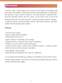
The ECO series, a high-frequency sine wave inverter, adopts a fully digital intelli-
gent design and voltage-current dual closed-loop control algorithm. Featured with
fast response, high conversion efficiency, low Total Harmonic Distortion(THD),
and high reliability running, the ECO series can be widely used in the DC-AC
off-grid systems (such as vehicle systems, security monitoring systems, emergen-
cy lighting systems, household power systems, field power systems, and other
systems requiring higher power quality).
Features:
• Pure sine wave output
• Input to output electrical isolation
• Output power factor up to 1
• Input Protection: Low-voltage, Over-voltage
• Output Protection: Overload, Short circuit, Overheating
• RS485 com. port to realize remote monitoring
• External switch design, matched with EPEVER products, to expand inverter
control function and reduce power consumption
• Diversified AC output sockets
• EN/IEC62109-1/2, EN61000-6-2/4, and FCC approved
For inverters with 12V/24V input voltage, the RS485/RJ11 port has NO commu-
nication isolation design. This function (communication isolation design) is just for
inverters with 48V input voltage.
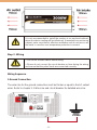
Overview

ʏCooling Fan
• Conditions to start the cooling fan:
The heat sink temperature is higher than 45 or The internal inverter temperature
is higher than 45 or The output power is higher than 50% of the rated power
• Conditions to stop the cooling fan:
The heat sink temperature is lower than 40 and The internal inverter tempera-
ture is lower than 40 and The output power is lower than 40% of the rated power
ʐThe AC output port varies with different products. Please refer to chapter
3 Naming Rule for the Specific Supported Types.
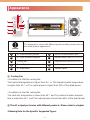
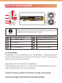
Appearance
CAUTION
The appearance varies with different product models; please refer to
the actual product appearance.
1
2
3
4
5
6
7
8
9
10
DC input terminal positive
DC input terminal negative
Cooling fan
Grounding terminal
AC output port
RS485 communication port
Remote switch port
External switch port
Indicator
Inverter switch
(RJ11, Reserved)
To connect an
external relay
ʏ
ʑ
ʒ
ʐ
96
43
3
7
8
10
2
1
5
5

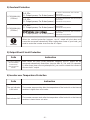
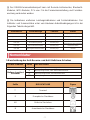
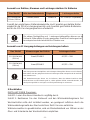
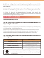
1.Instructions for the Aanti-Reverse and Anti-Surge Current Protection
ʔThe RS485 communication port can be connected to the remote meter, Blue-
tooth module, WIFI module, PC, etc., for parameter setting and remote monitor-
ing.
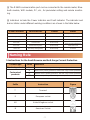
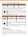
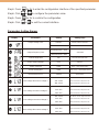
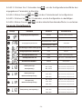
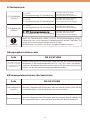
ʓIndicators include the Power indicator and Fault indicator. The indicator and
buzzer status under different working conditions are shown in the table below.
Naming Rule
Power indicator
Green ON
Green slowly flashing(1/4Hz)
Green fast flashing (1Hz)
Green OFF
Green OFF
Green ON
Fault indicator
Red OFF
Red OFF
Red OFF
Red ON solid
Red fast flashing (1Hz)
Red slowly flashing(1/4Hz)
Buzzer
No beeps
Buzzer beeps.
Buzzer beeps.
Buzzer beeps.
Buzzer beeps.
Buzzer beeps.
Status
Output voltage normal
Input under voltage
Input over voltage
Inverter over temperature
Heat sink over temperature
Load short-circuit
Overload
Suffix
No
R
S
RS
Product type
Standard products
Customized
products
Suffix
T
E
UK
N
Instruction
Terminal
European socket
United Kingdom socket
American Socket
Figure
Definition
Without reverse polarity and anti-surge current protection
With reverse polarity protection, without anti-surge current protection
Without reverse polarity protection, with anti-surge current protection
With reverse polarity and anti-surge current protection

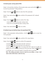
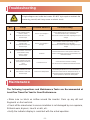
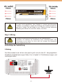
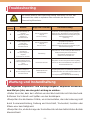
GFCI Socket Needs to be Tested After Power-on to Ensure Proper Operation.
A.Preparation
Connect a circuit breaker and an AC load (it is recommended to use a night light
to observe the status conveniently) to the GFCI socket. Turn on the inverter after
confirming the wiring.
B.Testing
1) If the red LED is ON solid, it indicates that the GFCI socket is damaged; please
replace a new one.
2) If the LED is green ON after it flashes in red three times, connect the circuit
breaker, and the night light will be turned on. Then, press the "TEST" button to
observe the testing status:
The "TEST" button always pops up, and the night light keeps ON solid. It indicates that the GFCI
wiring is an error; please correct it.
The "TEST" button goes down, while the "RESET" button pops up. The LED and the night light are
turned off, indicating the GFCI socket is normal (Note: Press the "RESET" button again to recover the
load output).

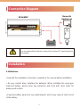
5.1Attentions
• Read all the installation instructions carefully in the manual before installation.
• Be very careful when installing the batteries. When installing the open-type
lead-acid battery, please wear eye protection and rinse with clean water for
battery acid contact.
• Keep the battery away from any metal objects, which may cause a short circuit
of the battery.
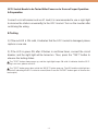
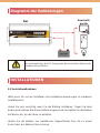
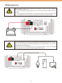
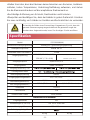
Connection Diagram
Installation
CAUTION
It is recommended to directly connect the inverter DC input terminal to
the battery.
Invweter Domestic
Appliances

• Loose power connectors and corroded wires may result in high heat, melt wire
insulation, burn surrounding materials, or cause a fire. Ensure tight connections
and secure cables with cable clamps to prevent them from swaying in moving
applications.
• The DC input voltage must strictly follow the parameter table. Too high or too low
DC input voltage affects the normal operation and may damage the inverter. DC
input 12V: Surge voltage < 20V. DC input 24V: Surge voltage < 40V. DC input 48V:
Surge voltage < 80V.
• Select the system cables according to 3.5A/mm2 or less current density.
• Avoid direct sunlight and rain infiltration when installing it outdoor.
• After turning off the power switch, do not open or touch the internal component
immediately. Performing related operations after 10 minutes is recommended.
• Do not install the inverter in a harsh environment such as humid, salt spray,
corrosion, greasy, flammable, explosive, or dust accumulation.
• The AC output is of high voltage, do not touch the wiring connection to avoid
electric shock.
• To prevent injury, do not touch the fan while it is working.
5.2Wire Size and Circuit Breaker
The wiring and installation methods conform to the national and local electrical
code requirements.

Wire, terminals, and circuit breaker selection for battery
According to the recommended battery wire size, 2 battery wires, connected
in parallel are necessary for the 230Vac outpur version and 4 battery wires
connected in parallel are necessary for the 120Vac output version.
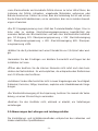
5.3Mounting
Installation procedures:
Step 1: Read this manual carefully.
Step 2: Determine the installation location and heat-dissipation space
The inverter should be installed in a place with sufficient airflow through the dissi-
pation pad of the inverter. And a minimum clearance of 150mm from the upper
and lower edges of the inverter is recommended to ensure natural thermal
convection.
CAUTION
The above wire size and circuit breaker size are for reference only;
please choose a suitable wire and circuit breaker according to the
actual situation.
CAUTION
•
The above wire size and circuit breaker size are for reference only;
please choose a suitable wire and circuit breaker according to the
actual situation.
•
The wire size is only for reference. If there is a long distance between
the inverter and the battery, larger wires should be used to reduce
voltage drop and improve system performance.
Model Battery wire size
25mm2/3AWG
Ring terminal
RNB60-6
Circuit breaker
DC-100A(2P in parallel)
Wire and circuit breaker selection for AC output
Model Wire size
6mm2/10AWG
4mm2/11AWG
Circuit breaker
AC/2P—50A
AC/2P—25A
ECO3000W(HN)
120Vac/230Vac
ECO3000W(HN)
(120Vac)
ECO3000W(HN)
(230Vac)

Wiring Sequence
1.Ground Connection
The wire size for the ground connection must be thicker or equal to the AC output
wires. Refer to chapter 5.2 Wire size and circuit breaker for detailed wire size.
9ZKV =OXOTM
CAUTION
CAUTION
•
Turn off the inverter switch before wiring.
•
Please do not connect the circuit breaker or fuse during the wiring
and ensure that the poles' leads are connected correctly.
It is not recommended to install the product in an enclosed cabinet,
where the device cooling will be influenced. If mounted in an enclosure
cabinet, make sure there’s effective ventilation and do not turn on all
the loads in case the over temperature protection is caused.
Ground

2.Battery Connection
WARNING
CAUTION
A fuse must be installed on the battery side, conformed to the following require-
ments.
1. Fuse voltage is 1.5 to 2 times the inverter's rated voltage.
2. Fuse current is 2 to 2.5 times the inverter's rated current.
3. Distance between the fuse and the battery cannot be farther than 150mm.
•The AC loads shall be determined by the continuous output power of the
inverter. The surge power of the AC load must be lower than the instantaneous
surge power of the inverter, or the inverter will be damaged.
•The N pole of the AC output port cannot be grounded. If grounding the N pole
is necessary, please purchase the IPower-Plus-B series.

Step 4Turn on the Inverter
(1)Connect the breaker at the inverter input terminal or the fuse at the battery
terminal.
(2)Turn on the inverter switch, and the green indicator will be lighted on, which
states a normal AC output.
(3)Connect the breaker at the AC load terminal, turn on the AC loads, and check
the system working status.
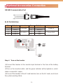
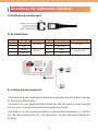
1)RS485 Communication Port
RJ45 Pin Definition:
Optional Accessories Connection
Pin
1
2
3
4
Definition
+5VDC
+5VDC
RS485-B
RS485-B
Pin
5
6
7
8
Definition
RS485-A
RS485-A
GND
GND
Instruction
5V/200mA
RS485-B
Instruction
RS485-A
Power GND

(4)If the FAULT indicator flashes red and the buzzer alarms after powering the
inverter, please immediately turn off the load and the inverter. Clear the faults
according to chapter 8 Troubleshooting. After clearing the faults, please operate
the inverter again by following the above steps.
ECO parameters such as power saving mode, baud rate, output voltage class, and
output frequency class can be set on the remote meter, phone APP, or PC
software. The following chapters take parameters setting on the remote meter as
an example (for connection of the remote meter, please refer to chapter 5.3
Mounting).
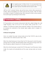
6.1Power Saving Mode
Users can enable the power saving mode and set the PSI/PSO value by the
remote meter (The minimum power step is 1VA).
When the actual load power is lower than the PSI (the power to enter the power
saving mode), the system will automatically switch to the power saving mode.And
then, the device output is turned on for 1s and turned off for 5s.
When the actual load power exceeds the PSO (the power to exit the power saving
mode), the inverter will automatically exit the power saving mode and resume
work.
Parameters Setting
CAUTION
When supplying power for different loads, it is recommended to first
turn on the load with a large impulse current.And then turn on the load
with a smaller impulse current after the load output is stable.

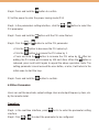
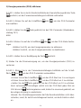
1) Enable power saving mode (PSE)
Step1: In the real-time interface of the remote meter, press and hold the button
to enter the parameters setting interface.
Step2: Click the or button to select the PSE parameter.
Step3: Press and hold the button until the PSE parameter (OFF default)
flashes.
Step4: Click the or button to set the PSE state.
• Select ON to enable the power saving mode.
• Select OFF to disable the power saving mode.
Step5: Press and hold the button to confirm.
2) Set the Power to Exit the Power Saving Mode (PSO)
Step1: In the parameters setting interface, click the or button to select the
PSO parameter.
Step2: Press and hold the button until the PSO value flashes.
Step3: Click the or button to set the PSO parameter.
• Click the button to decrease the PSO value by 1.
• Click the button to increase the PSO value by 1.
• Press and hold the button to increase the PSO value by 10. After ten
adding, the PSO value will increase by 100 each time. When the button
is released, press and hold it again to repeat the above operation.
Note: The setting parameter cannot exceed the user define, or else; it will
return to the initial value to start the loop.

Step4: Press and hold the button to confirm.
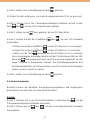
3) Set the power to enter the power saving mode (PSI)
Step1: In the parameters setting interface, click the or button to select the
PSI parameter.
Step2: Press and hold the button until the PSI value flashes.
Step3: Click the or button to set the PSI parameter.
Step4: Press and hold the button to confirm.
6.2Other Parameters
Users can set the baud rate, output voltage class and output frequency class, etc.
by the remote meter.
Operation:
Step1: In the real-time interface, press for 2s to enter the parameter setting
interface.
Step2: Click or to select the parameter to be configured.
• Click the button to decrease the PSI value by 1.
• Click the button to increase the PSI value by 1.
• Press and hold the button to increase the PSI value by 10. After ten
adding, the PSI value will increase by 100 each time. When the button is
released, press and hold it again to repeat the above operation. Note: The
setting parameter cannot exceed the user define, or else; it will return to the
initial value to start the loop.

Step3: Press for 2s to enter the configuration interface of the specified parameter.
Step4: Click or to configure the parameter value.
Step5: Press for 2s to confirm the configuration.
Step6: Click + to exit the current interface.
Parameters Setting Range:
Parameters
Output voltage class
LCD backlight time
Power Saving Enable
Power Saving In
Power Saving Out
Baud Rate Select
Low voltage disconnect voltage
Low voltage reconnect voltage
Over voltage reconnect voltage
Over voltage disconnect voltage
Display Default
220VAC
110VAC
220/230/240VAC: 50Hz
100/110/120VAC: 60Hz
30s
OFF
20VA
40VA
115200
12V: 10.8V
24V: 21.6V
48V: 43.2V
12V: 12.5V
24V: 25V
48V: 50V
12V: 14.5V
24V: 29V
48V: 58V
12V: 16V
24V: 32V
48V: 64V
Setting range
220VAC/230VAC/240VAC
100VAC/110VAC/120VAC
30s/ 60s/100s(ON solid)
ON/OFF
20VA ~ (20%*rated power)
(20VA + PSI) ~ (50%*rated power)
9600/115200
12V: 10.5V~14.2V; step size 0.1V
24V: 21V-30.2V; step size 0.1V
48V: 42V-62.4V; step size 0.1V
12V: 11.5V~15.2V; step size 0.1V
24V: 22V-31.2V; step size 0.1V
48V: 43V-63.4V; step size 0.1V
12V: 11.5V~15.2V; step size 0.1V
24V: 22V-31.2V; step size 0.1V
48V: 43V-63.4V; step size 0.1V
12V: 10.5V~14.2V; step size 0.1V
24V: 21V-30.2V; step size 0.1V
48V: 42V-62.4V; step size 0.1V
50Hz/60Hz
Output frequency class
Seite wird geladen ...
Seite wird geladen ...
Seite wird geladen ...
Seite wird geladen ...
Seite wird geladen ...
Seite wird geladen ...
Seite wird geladen ...
Seite wird geladen ...
Seite wird geladen ...
Seite wird geladen ...
Seite wird geladen ...
Seite wird geladen ...
Seite wird geladen ...
Seite wird geladen ...
Seite wird geladen ...
Seite wird geladen ...
Seite wird geladen ...
Seite wird geladen ...
Seite wird geladen ...
Seite wird geladen ...
Seite wird geladen ...
Seite wird geladen ...
Seite wird geladen ...
Seite wird geladen ...
Seite wird geladen ...
Seite wird geladen ...
Seite wird geladen ...
Seite wird geladen ...
Seite wird geladen ...
Seite wird geladen ...
-
 1
1
-
 2
2
-
 3
3
-
 4
4
-
 5
5
-
 6
6
-
 7
7
-
 8
8
-
 9
9
-
 10
10
-
 11
11
-
 12
12
-
 13
13
-
 14
14
-
 15
15
-
 16
16
-
 17
17
-
 18
18
-
 19
19
-
 20
20
-
 21
21
-
 22
22
-
 23
23
-
 24
24
-
 25
25
-
 26
26
-
 27
27
-
 28
28
-
 29
29
-
 30
30
-
 31
31
-
 32
32
-
 33
33
-
 34
34
-
 35
35
-
 36
36
-
 37
37
-
 38
38
-
 39
39
-
 40
40
-
 41
41
-
 42
42
-
 43
43
-
 44
44
-
 45
45
-
 46
46
-
 47
47
-
 48
48
-
 49
49
-
 50
50


ECO-WORTHY ECO-WORTHY DC24V Pure Sine Wave Off Grid Inverter Benutzerhandbuch
- Typ
- Benutzerhandbuch
in anderen Sprachen
Andere Dokumente
-
Samlexpower PST-300S-12E Bedienungsanleitung
-
Tripp Lite APSWX-Series Solar Sinewave Inverter Charger Bedienungsanleitung
-
 Giandel PS-1000PDR 1000W Pure Sine Wave Inverter Benutzerhandbuch
-
 PowerWalker VFI 1500RT Benutzerhandbuch
-
 Power Walker VFI 10000CP 3/3 Benutzerhandbuch
-
Tripp Lite S3M100KX, S3M120KX, S3M160KX, S3M200KX Bedienungsanleitung
-
-
Western WRD Bedienungsanleitung
-
Bluetti AC200MAX Benutzerhandbuch
-
BlueWalker PowerWalker VFI 1000 LCD Spezifikation


