MSI 7C71 Bedienungsanleitung
- Kategorie
- Motherboards
- Typ
- Bedienungsanleitung
Dieses Handbuch eignet sich auch für

I
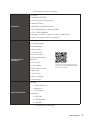
Quick Start
Quick Start
Thank you for purchasing the MSI® MEG Z490 ACE motherboard. This
Quick Start section provides demonstration diagrams about how to
install your computer. Some of the installations also provide video
demonstrations. Please link to the URL to watch it with the web
browser on your phone or tablet. You may have even link to the URL
by scanning the QR code.
Kurzanleitung
Danke, dass Sie das MSI® MEG Z490 ACE Motherboard gewählt
haben. Dieser Abschnitt der Kurzanleitung bietet eine Demo zur
Installation Ihres Computers. Manche Installationen bieten auch
die Videodemonstrationen. Klicken Sie auf die URL, um diese
Videoanleitung mit Ihrem Browser auf Ihrem Handy oder Table
anzusehen. Oder scannen Sie auch den QR Code mit Ihrem Handy,
um die URL zu öffnen.
Présentation rapide
Merci d’avoir choisi la carte mère MSI® MEG Z490 ACE. Ce manuel
fournit une rapide présentation avec des illustrations explicatives
qui vous aideront à assembler votre ordinateur. Des tutoriels vidéo
sont disponibles pour certaines étapes. Cliquez sur le lien fourni
pour regarder la vidéo sur votre téléphone ou votre tablette. Vous
pouvez également accéder au lien en scannant le QR code qui lui est
associé.
Быстрый старт
MEG Z490
ACE

II
Quick Start
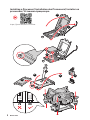
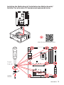
Installing a Processor/ Installation des Prozessors/ Installer un
processeur/ Установка процессора
⚽
https://youtu.be/4ce91YC3Oww
1
2
3
6
4
5
7
8
9

III
Quick Start
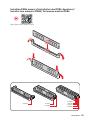
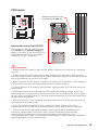
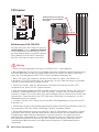
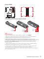
Installing DDR4 memory/ Installation des DDR4-Speichers/
Installer une mémoire DDR4/ Установка памяти DDR4
http://youtu.be/T03aDrJPyQs
⚽
DIMMA2 DIMMA2
DIMMB2
DIMMA1
DIMMA2
DIMMB1
DIMMB2

IV
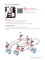
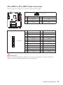
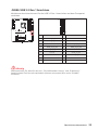
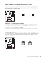
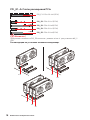
Quick Start
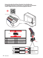
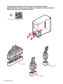
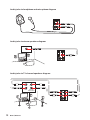
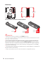
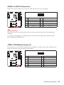
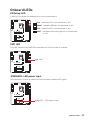
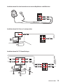
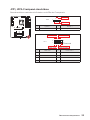
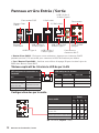
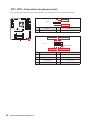
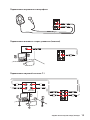
Connecting the Front Panel Header/ Anschließen der
Frontpanel-Stiftleiste/ Connecter un connecteur du panneau
avant/ Подключение разъемов передней панели
http://youtu.be/DPELIdVNZUI
HDD LED
RESET SW
JFP1
HDD LED
HDD LED +
POWER LED +
POWER LED
1
2 10
9
+
+
+
+
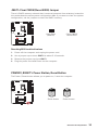
Power LED
HDD LED Reset Switch
Reserved
Power Switch
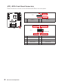
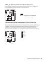
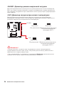
JFP1
1 HDD LED + 2 Power LED +
3 4
5 Reset Switch 6 Power Switch
7 Reset Switch 8 Power Switch
9 Reserved 10 No Pin
RESET SW
POWER SW
POWER LED+
POWER LED-
HDD LED
⚽

V
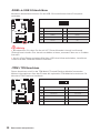
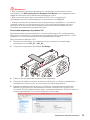
Quick Start
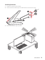
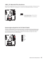
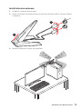
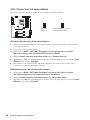
Installing the Motherboard/ Installation des Motherboards/
Installer la carte mère/ Установка материнской платы
1
2
https://youtu.be/wWI6Qt51Wnc
⚽
Torque:
3 kgf·cm*
*3 kgf·cm
= 0.3 N·m
= 2.6 lbf·in

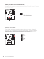
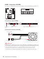
VI
Quick Start
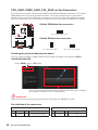
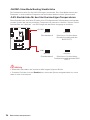
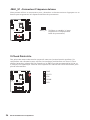
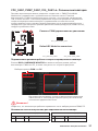
http://youtu.be/gkDYyR_83I4
⚽
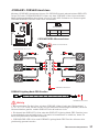
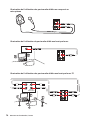
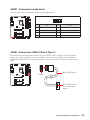
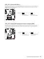
ATX_PWR1
CPU_PWR1
CPU_PWR2
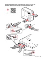
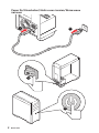
Connecting the Power Connectors/ Stromanschlüsse
anschliessen/ Connecter les câbles du module d’alimentation/
Подключение разъемов питания

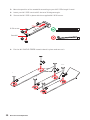
VII
Quick Start
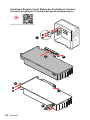
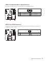
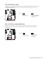
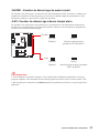
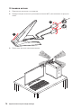
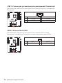
Installing SATA Drives/ Installation der SATA-Laufwerke/
Installer le disque dur SATA/ Установка дисков SATA
http://youtu.be/RZsMpqxythc
1
2
3
4
5
⚽

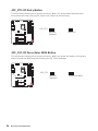
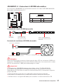
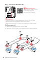
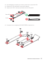
VIII
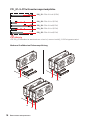
Quick Start
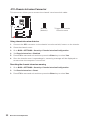
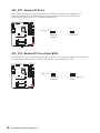
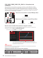
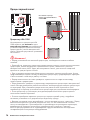
1
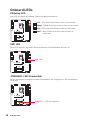
http://youtu.be/mG0GZpr9w_A
2
3
4
5
6
Installing a Graphics Card/ Einbau der Grafikkarte/ Installer
une carte graphique/ Установка дискретной видеокарты
⚽

IX
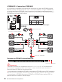
Quick Start
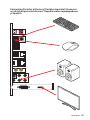
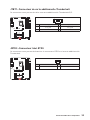
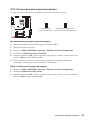
Connecting Peripheral Devices/ Peripheriegeräte/ Connecter
un périphérique anschliessen/ Подключение периферийных
устройств

X
Quick Start
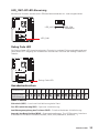
4
3
1
2
Power On/ Einschalten/ Mettre sous-tension/ Включение
питания

1
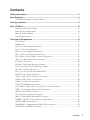
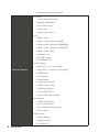
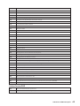
Contents
Contents
Safety Information ................................................................................................. 3
Specifications ......................................................................................................... 4
JCORSAIR1 Connector Specification ...................................................................... 9
Package contents .................................................................................................. 9
Rear I/O Panel ..................................................................................................... 10
LAN Port LED Status Table .................................................................................. 10
Audio Ports Configuration .................................................................................... 10
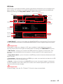
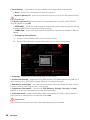
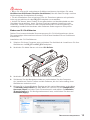
Realtek Audio Console ......................................................................................... 11
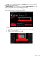
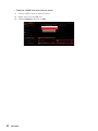
Installing Antennas ............................................................................................... 13
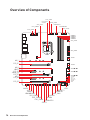
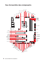
Overview of Components .................................................................................... 14
CPU Socket ........................................................................................................... 15
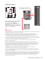
DIMM Slots ............................................................................................................ 16
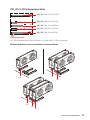
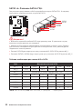
PCI_E1~5: PCIe Expansion Slots .......................................................................... 17
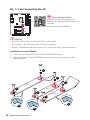
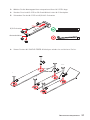
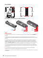
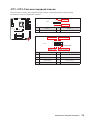
M2_1~3: M.2 Slots (Key M) ................................................................................... 19
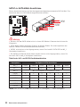
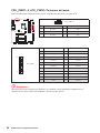
SATA1~6: SATA 6Gb/s Connectors ....................................................................... 21
JFP1, JFP2: Front Panel Connectors ................................................................... 22
CPU_PWR1~2, ATX_PWR1: Power Connectors ................................................... 23
JBLK_U1: Base clock Plus connector .................................................................. 24
.............................................................................................. 24
JSLOW1: Slow Mode Booting Jumper .................................................................. 25
JLN1: Low Temperature Booting Jumper ........................................................... 25
JOC_RT1: OC Retry Button ................................................................................... 26
JOC_FS1: OC Force Enter BIOS Button ............................................................... 26
JAUD1: Front Audio Connector ............................................................................ 27
............................................................ 27
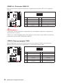
JUSB2: USB 3.2 Gen 1 Connector ........................................................................ 28
JUSB3~4: USB 2.0 Connectors ............................................................................. 29
JTPM1: TPM Module Connector ........................................................................... 29
CPU_FAN1, PUMP_FAN1, SYS_FAN1~6: Fan Connectors .................................. 30
...................................................... 31
JRTD3: Intel RTD3 Connector .............................................................................. 31
JCI1: Chassis Intrusion Connector ....................................................................... 32
JBAT1: Clear CMOS (Reset BIOS) Jumper ........................................................... 33
POWER1, RESET1: Power Button, Reset Button ................................................. 33
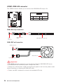
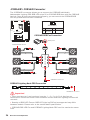
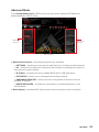
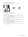
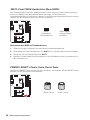
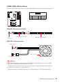
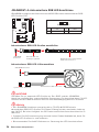
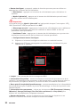
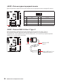
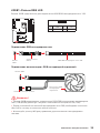
JRGB1: RGB LED connector ................................................................................. 34
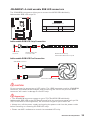
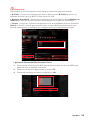
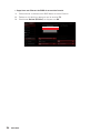
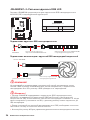
JRAINBOW1~2: Addressable RGB LED connectors ............................................ 35
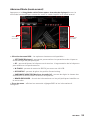
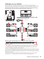
JCORSAIR1: CORSAIR Connector ........................................................................ 36

2
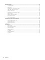
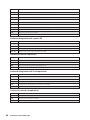
Contents
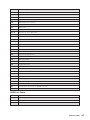
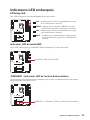
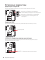
Onboard LEDs ...................................................................................................... 37
EZ Debug LED ....................................................................................................... 37
XMP LED ............................................................................................................... 37
JPWRLED1: LED power input ............................................................................... 37
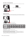
LED_SW1: EZ LED Control ................................................................................... 38
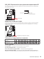
Debug Code LED ................................................................................................... 38
Hexadecimal Character Table .............................................................................. 38
Boot Phases .......................................................................................................... 38
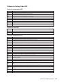
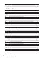
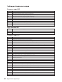
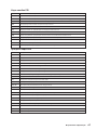
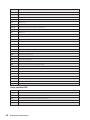
Debug Code LED Table ......................................................................................... 39
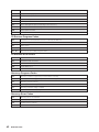
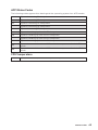
ACPI States Codes ................................................................................................ 43
CPU Temperature ................................................................................................. 43
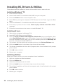
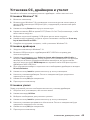
Installing OS, Drivers & Utilities ......................................................................... 44
Installing Windows® 10 ......................................................................................... 44
Installing Drivers .................................................................................................. 44
Installing Utilities ................................................................................................. 44
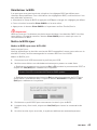
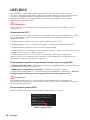
UEFI BIOS ............................................................................................................. 45
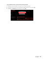
BIOS Setup ............................................................................................................ 46
Entering BIOS Setup ............................................................................................. 46
Resetting BIOS ...................................................................................................... 47
Updating BIOS ....................................................................................................... 47
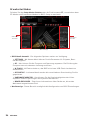
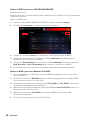
EZ Mode ................................................................................................................ 49
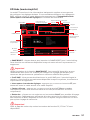
Advanced Mode .................................................................................................... 53
OC Menu................................................................................................................ 54

3
Safety Information
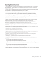
Safety Information
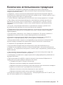
∙ The components included in this package are prone to damage from electrostatic
discharge (ESD). Please adhere to the following instructions to ensure successful
computer assembly.
∙ Ensure that all components are securely connected. Loose connections may cause
the computer to not recognize a component or fail to start.
∙ Hold the motherboard by the edges to avoid touching sensitive components.
∙ It is recommended to wear an electrostatic discharge (ESD) wrist strap when
handling the motherboard to prevent electrostatic damage. If an ESD wrist strap is
not available, discharge yourself of static electricity by touching another metal object
before handling the motherboard.
∙
pad whenever the motherboard is not installed.
∙ Before turning on the computer, ensure that there are no loose screws or metal
components on the motherboard or anywhere within the computer case.
∙ Do not boot the computer before installation is completed. This could cause
permanent damage to the components as well as injury to the user.
∙ If you need help during any installation step, please consult a certified computer
technician.
∙ Always turn off the power supply and unplug the power cord from the power outlet
before installing or removing any computer component.
∙ Keep this user guide for future reference.
∙ Keep this motherboard away from humidity.
∙ Make sure that your electrical outlet provides the same voltage as is indicated on
the PSU, before connecting the PSU to the electrical outlet.
∙ Place the power cord such a way that people can not step on it. Do not place
anything over the power cord.
∙ All cautions and warnings on the motherboard should be noted.
∙ If any of the following situations arises, get the motherboard checked by service
personnel:
▪ Liquid has penetrated into the computer.
▪ The motherboard has been exposed to moisture.
▪ The motherboard does not work well or you can not get it work according to user
guide.
▪ The motherboard has been dropped and damaged.
▪ The motherboard has obvious sign of breakage.
∙ Do not leave this motherboard in an environment above 60°C (140°F), it may damage
the motherboard.

4
Specifications
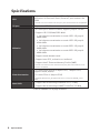
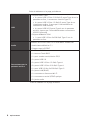
Specifications
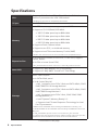
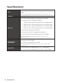
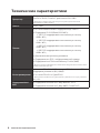
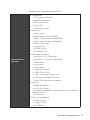
CPU
Supports 10th Gen Intel® Core™ and Pentium® Gold /
Celeron® processors for LGA 1200 socket*
* Please go to intel.com for compatibility information.
Chipset Intel® Z490 Chipset
Memory
∙ 4x DDR4 memory slots, support up to 128GB*
∙ Supports 1R 2133/2666/2933 MHz*
▪ 1DPC 1R Max speed up to 4800+ MHz
▪ 1DPC 2R Max speed up to 4266+ MHz
▪ 2DPC 1R Max speed up to 4400+ MHz
▪ 2DPC 2R Max speed up to 4000+ MHz
∙
∙
∙ Supports Intel® Extreme Memory Profile (XMP)
* Please refer www.msi.com for more information on compatible memory
Expansion Slot
∙ 3x PCIe 3.0 x16 slots (2 from CPU, 1 from PCH, support
16/0/4, 8/8/4)*
∙ 2x PCIe x1 slots (from PCH)
* PCI_E5 bandwidth will switch from x4 to x1 when M2_3 SSD is inserted
Multi-GPU
∙
∙
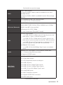
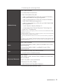
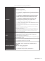
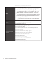
Storage
Intel® Z490 Chipset
∙ 6x SATA 6Gb/s ports*
∙ 3x M.2 slots (Key M)
▪ M2_1 supports up to PCIe 3.0 x4 and SATA 6Gb/s, 2242/
2260/ 2280/ 22110 storage devices*
▪ M2_2 supports up to PCIe 3.0 x4 and SATA 6Gb/s, 2242/
2260/ 2280 storage devices**
▪ M2_3 supports up to PCIe 3.0 x4, 2242/ 2260/ 2280
storage devices***
▪ Intel® Optane™ Memory Ready****
▪ Supports Intel® Smart Response Technology for Intel
Core™ processors
* SATA2 will be unavailable when installing M.2 SATA SSD in the M2_1 slot.
** SATA5 & SATA6 will be unavailable when installing M.2 SATA/PCIe SSD in the
M2_2 slot.
*** M2_3 bandwidth will switch from x4 to x2 when PCI_E5 is inserted.
**** Before using Intel
®
Optane™ memory modules, please ensure that you have
updated the drivers and BIOS to the latest version from MSI website.
Continued on next page

5
Specifications
Continued from previous page
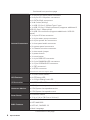
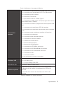
RAID
Intel® Z490 Chipset
∙ Supports RAID 0, RAID1, RAID 5 and RAID 10 for SATA
storage devices
∙ Supports RAID 0, RAID 1 and RAID 5 for M.2 PCIe storage
devices
LAN
∙ 1x Realtek® 8125B 2.5G LAN controller
∙ 1x Intel® I219V 1G LAN controller
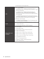
Wireless/ Bluetooth
Intel® AX201
∙
∙ 802.11ac; WiFi 6 pre certified
∙ Bluetooth 5.0, FIPS, FISMA
∙
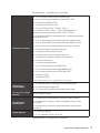
USB
∙ Intel® Z490 Chipset
▪ 4x USB 3.2 Gen 2 10Gbps ports
▪
back panel, 2 ports through the internal USB connector)
▪ 6x USB 2.0 ports
ports through the internal USB 2.0 connectors)
∙ ASMedia® 3241 chipset
▪ 1x USB 3.2 Gen 2x2 20Gbps
panel
Audio
Realtek® ALC1220 Codec + ESS E9018Q2C combo DAC
∙
∙ Supports S/PDIF output
Back Panel
Connectors
∙ 1x Clear CMOS
∙ 1x Flash BIOS button
∙ 1x PS/2 keyboard/ mouse combo port
∙ 2x USB 2.0 ports
∙
∙
∙
∙ 2x LAN (RJ45) ports
∙
∙ 1x Optical S/PDIF OUT connector
∙ 5x OFC audio jacks
Continued on next page

6
Specifications
Continued from previous page
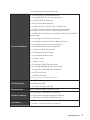
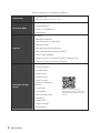
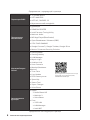
Internal Connectors
∙
∙
∙ 6x SATA 6Gb/s connectors
∙
∙
∙ 1x USB 3.2 Gen 1 5Gbps connector (supports additional 2
USB 3.2 Gen 1 5Gbps ports)
∙ 2x USB 2.0 connectors (supports additional 4 USB 2.0
ports)
∙
∙
∙
∙ 1x front panel audio connector
∙ 2x system panel connectors
∙ 1x Chassis Intrusion connector
∙ 1x slow mode jumper
∙ 1x power button
∙ 1x reset button
∙
∙
∙
∙ 1x TBT connector*
∙ 1x RTD3 connector
*Thunderbolt card need support RTD3
LED Features
∙ 1x LED Control switch
∙ 4x EZ Debug LED
∙
I/O Controller NUVOTON NCT6687 Controller Chip
Hardware Monitor
∙ CPU/System temperature detection
∙ CPU/System fan speed detection
∙ CPU/System fan speed control
Form Factor
∙ ATX Form Factor
∙ 12 in. x 9.6 in. (30.5 cm x 24.4 cm)
BIOS Features
∙ 1x 256 Mb flash
∙ UEFI AMI BIOS
∙ ACPI 6.2, SM BIOS 3.2
∙
Continued on next page

7
Specifications
Continued from previous page
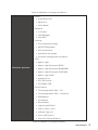
Software
∙ Drivers
∙ DRAGON CENTER
∙ Intel Extreme Tuning Utility
∙ Nahimic Audio
∙ MSI App Player(BlueStacks)
∙ Open Broadcaster Software (OBS)
∙
∙ Google Chrome™, Google Toolbar, Google Drive
∙ Norton™ Internet Security Solution
Dragon Center
Features
∙ Gaming Mode
∙ Gaming Hotkey
∙ LAN Manager
∙ Mystic Light
∙ Ambient Link
∙ User Scenario
∙ Monitor(Hardware
Monitor)
∙ True Color
∙ Live Update
∙ DPC Latency tuner
∙ Speed Up
∙ Smart Tool
∙ Super Charger
∙ Voice Boost
Please refer to http://download.msi.
com/manual/mb/DRAGONCENTER2.
pdf for more details.
Special Features
∙ Audio
▪ Audio Boost HD
▪ Nahimic 3
▪ Voice Boost
∙ Network
▪ 2.5G LAN
▪ LAN Manager
▪ Intel WiFi
Continued on next page

8
Specifications
Continued from previous page
Special Features
∙ Cooling
▪ Frozr Heatsink Design
▪ MOSFET Baseplate
▪ M.2 Shield Frozr
▪ Pump Fan
▪ Smart Fan Control
∙ LED
▪ Mystic Light
▪ Mystic Light Extension (RGB)
▪ Mystic Light Extension (RAINBOW)
▪ Mystic Light Extension (CORSAIR)
▪ Mystic Light SYNC
▪ Ambient Link
▪ EZ LED Control
▪ EZ DEBUG LED
∙ Performance
▪ Multi GPU – SLI Technology
▪ Multi GPU – CrossFire Technology
▪ DDR4 Boost
▪ Core Boost
▪ Game Boost
▪ Lightning USB 20G
▪ USB 3.2 Gen 2 10G
▪ USB with Type A+C
▪
▪ Dual CPU Power (8+8pin)
∙ Protection
▪ DDR4 Steel Armor
▪
▪
▪ Chest Plate
∙ Experience
▪ Smart Button
▪ Dragon Center
▪ Click BIOS 5

9
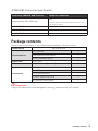
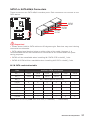
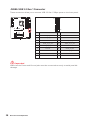
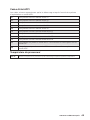
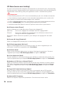
Package contents
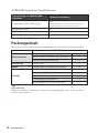
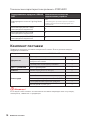
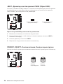
JCORSAIR1 Connector Specification
Supporting CORSAIR RGB Products Maximum connection
Lighting Node PRO LED Strip
20*
* 20% brightness is recommended when the number of
LED strips exceeds 8.
HD120 RGB Fan 6
SP120 RGB Fan 6
LL120 RGB Fan 6
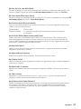
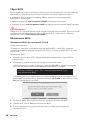
Package contents
Please check the contents of your motherboard package. It should contain:
Motherboard MEG Z490 ACE
Documentation
User manual 1
1
Quick installation guide 1
Application Driver DVD 1
Cables SATA 6G cables (2 cables/pack) 2
Accessories
1
Case badge 1
SATA cable stickers 1
Product registration card 1
M.2 screws (3 pcs./pack) 1
⚠
Important
If any of the above items are damaged or missing, please contact your retailer.

10
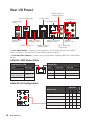
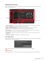
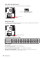
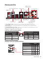
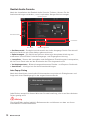
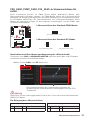
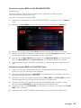
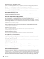
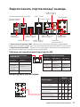
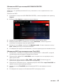
Rear I/O Panel
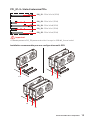
Audio Ports Configuration
Audio Ports
Channel
2 4 6 8
Rear Speaker Out
Mic In
Blank: empty)
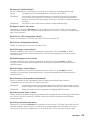
Rear I/O Panel
PS/2 Combo port
2.5 Gbps LAN
1 Gbps LAN
Audio Ports
Optical
Clear CMOS
button
connectors
Flash BIOS
Button
∙ Clear CMOS button
∙ Flash BIOS Port/ Buttone refer to page 48 for Updating BIOS with Flash BIOS
Button.
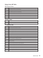
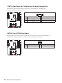
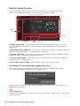
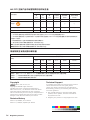
Link/ Activity LED
Status Description
Off No link
Yellow (2.5Gb LAN)
Green (1Gb LAN)
Linked
Blinking Data activity
Speed LED
Status 2.5 Gbps LAN 1 Gbps LAN
Off 10 Mbps
Green 100 Mbps 100 Mbps
Orange 2.5 Gbps 1 Gbps
LAN Port LED Status Table
USB 3.2 Gen 2
10Gbps Type A
USB 3.2 Gen 2
10Gbps Type A
USB 3.2 Gen 1
5Gbps Type A
USB 3.2 Gen 2x2
20Gbps Type C
Seite wird geladen ...
Seite wird geladen ...
Seite wird geladen ...
Seite wird geladen ...
Seite wird geladen ...
Seite wird geladen ...
Seite wird geladen ...
Seite wird geladen ...
Seite wird geladen ...
Seite wird geladen ...
Seite wird geladen ...
Seite wird geladen ...
Seite wird geladen ...
Seite wird geladen ...
Seite wird geladen ...
Seite wird geladen ...
Seite wird geladen ...
Seite wird geladen ...
Seite wird geladen ...
Seite wird geladen ...
Seite wird geladen ...
Seite wird geladen ...
Seite wird geladen ...
Seite wird geladen ...
Seite wird geladen ...
Seite wird geladen ...
Seite wird geladen ...
Seite wird geladen ...
Seite wird geladen ...
Seite wird geladen ...
Seite wird geladen ...
Seite wird geladen ...
Seite wird geladen ...
Seite wird geladen ...
Seite wird geladen ...
Seite wird geladen ...
Seite wird geladen ...
Seite wird geladen ...
Seite wird geladen ...
Seite wird geladen ...
Seite wird geladen ...
Seite wird geladen ...
Seite wird geladen ...
Seite wird geladen ...
Seite wird geladen ...
Seite wird geladen ...
Seite wird geladen ...
Seite wird geladen ...
Seite wird geladen ...
Seite wird geladen ...
Seite wird geladen ...
Seite wird geladen ...
Seite wird geladen ...
Seite wird geladen ...
Seite wird geladen ...
Seite wird geladen ...
Seite wird geladen ...
Seite wird geladen ...
Seite wird geladen ...
Seite wird geladen ...
Seite wird geladen ...
Seite wird geladen ...
Seite wird geladen ...
Seite wird geladen ...
Seite wird geladen ...
Seite wird geladen ...
Seite wird geladen ...
Seite wird geladen ...
Seite wird geladen ...
Seite wird geladen ...
Seite wird geladen ...
Seite wird geladen ...
Seite wird geladen ...
Seite wird geladen ...
Seite wird geladen ...
Seite wird geladen ...
Seite wird geladen ...
Seite wird geladen ...
Seite wird geladen ...
Seite wird geladen ...
Seite wird geladen ...
Seite wird geladen ...
Seite wird geladen ...
Seite wird geladen ...
Seite wird geladen ...
Seite wird geladen ...
Seite wird geladen ...
Seite wird geladen ...
Seite wird geladen ...
Seite wird geladen ...
Seite wird geladen ...
Seite wird geladen ...
Seite wird geladen ...
Seite wird geladen ...
Seite wird geladen ...
Seite wird geladen ...
Seite wird geladen ...
Seite wird geladen ...
Seite wird geladen ...
Seite wird geladen ...
Seite wird geladen ...
Seite wird geladen ...
Seite wird geladen ...
Seite wird geladen ...
Seite wird geladen ...
Seite wird geladen ...
Seite wird geladen ...
Seite wird geladen ...
Seite wird geladen ...
Seite wird geladen ...
Seite wird geladen ...
Seite wird geladen ...
Seite wird geladen ...
Seite wird geladen ...
Seite wird geladen ...
Seite wird geladen ...
Seite wird geladen ...
Seite wird geladen ...
Seite wird geladen ...
Seite wird geladen ...
Seite wird geladen ...
Seite wird geladen ...
Seite wird geladen ...
Seite wird geladen ...
Seite wird geladen ...
Seite wird geladen ...
Seite wird geladen ...
Seite wird geladen ...
Seite wird geladen ...
Seite wird geladen ...
Seite wird geladen ...
Seite wird geladen ...
Seite wird geladen ...
Seite wird geladen ...
Seite wird geladen ...
Seite wird geladen ...
Seite wird geladen ...
Seite wird geladen ...
Seite wird geladen ...
Seite wird geladen ...
Seite wird geladen ...
Seite wird geladen ...
Seite wird geladen ...
Seite wird geladen ...
Seite wird geladen ...
Seite wird geladen ...
Seite wird geladen ...
Seite wird geladen ...
Seite wird geladen ...
Seite wird geladen ...
Seite wird geladen ...
Seite wird geladen ...
Seite wird geladen ...
Seite wird geladen ...
Seite wird geladen ...
Seite wird geladen ...
Seite wird geladen ...
Seite wird geladen ...
Seite wird geladen ...
Seite wird geladen ...
Seite wird geladen ...
Seite wird geladen ...
Seite wird geladen ...
Seite wird geladen ...
Seite wird geladen ...
Seite wird geladen ...
Seite wird geladen ...
Seite wird geladen ...
Seite wird geladen ...
Seite wird geladen ...
Seite wird geladen ...
Seite wird geladen ...
Seite wird geladen ...
Seite wird geladen ...
Seite wird geladen ...
Seite wird geladen ...
Seite wird geladen ...
Seite wird geladen ...
Seite wird geladen ...
Seite wird geladen ...
Seite wird geladen ...
Seite wird geladen ...
Seite wird geladen ...
Seite wird geladen ...
Seite wird geladen ...
Seite wird geladen ...
Seite wird geladen ...
Seite wird geladen ...
Seite wird geladen ...
Seite wird geladen ...
Seite wird geladen ...
Seite wird geladen ...
Seite wird geladen ...
Seite wird geladen ...
Seite wird geladen ...
Seite wird geladen ...
Seite wird geladen ...
Seite wird geladen ...
Seite wird geladen ...
Seite wird geladen ...
Seite wird geladen ...
Seite wird geladen ...
Seite wird geladen ...
Seite wird geladen ...
Seite wird geladen ...
Seite wird geladen ...
Seite wird geladen ...
Seite wird geladen ...
Seite wird geladen ...
Seite wird geladen ...
Seite wird geladen ...
Seite wird geladen ...
Seite wird geladen ...
Seite wird geladen ...
Seite wird geladen ...
Seite wird geladen ...
Seite wird geladen ...
Seite wird geladen ...
Seite wird geladen ...
Seite wird geladen ...
Seite wird geladen ...
Seite wird geladen ...
Seite wird geladen ...
Seite wird geladen ...
Seite wird geladen ...
Seite wird geladen ...
Seite wird geladen ...
Seite wird geladen ...
Seite wird geladen ...
Seite wird geladen ...
Seite wird geladen ...
Seite wird geladen ...
-
 1
1
-
 2
2
-
 3
3
-
 4
4
-
 5
5
-
 6
6
-
 7
7
-
 8
8
-
 9
9
-
 10
10
-
 11
11
-
 12
12
-
 13
13
-
 14
14
-
 15
15
-
 16
16
-
 17
17
-
 18
18
-
 19
19
-
 20
20
-
 21
21
-
 22
22
-
 23
23
-
 24
24
-
 25
25
-
 26
26
-
 27
27
-
 28
28
-
 29
29
-
 30
30
-
 31
31
-
 32
32
-
 33
33
-
 34
34
-
 35
35
-
 36
36
-
 37
37
-
 38
38
-
 39
39
-
 40
40
-
 41
41
-
 42
42
-
 43
43
-
 44
44
-
 45
45
-
 46
46
-
 47
47
-
 48
48
-
 49
49
-
 50
50
-
 51
51
-
 52
52
-
 53
53
-
 54
54
-
 55
55
-
 56
56
-
 57
57
-
 58
58
-
 59
59
-
 60
60
-
 61
61
-
 62
62
-
 63
63
-
 64
64
-
 65
65
-
 66
66
-
 67
67
-
 68
68
-
 69
69
-
 70
70
-
 71
71
-
 72
72
-
 73
73
-
 74
74
-
 75
75
-
 76
76
-
 77
77
-
 78
78
-
 79
79
-
 80
80
-
 81
81
-
 82
82
-
 83
83
-
 84
84
-
 85
85
-
 86
86
-
 87
87
-
 88
88
-
 89
89
-
 90
90
-
 91
91
-
 92
92
-
 93
93
-
 94
94
-
 95
95
-
 96
96
-
 97
97
-
 98
98
-
 99
99
-
 100
100
-
 101
101
-
 102
102
-
 103
103
-
 104
104
-
 105
105
-
 106
106
-
 107
107
-
 108
108
-
 109
109
-
 110
110
-
 111
111
-
 112
112
-
 113
113
-
 114
114
-
 115
115
-
 116
116
-
 117
117
-
 118
118
-
 119
119
-
 120
120
-
 121
121
-
 122
122
-
 123
123
-
 124
124
-
 125
125
-
 126
126
-
 127
127
-
 128
128
-
 129
129
-
 130
130
-
 131
131
-
 132
132
-
 133
133
-
 134
134
-
 135
135
-
 136
136
-
 137
137
-
 138
138
-
 139
139
-
 140
140
-
 141
141
-
 142
142
-
 143
143
-
 144
144
-
 145
145
-
 146
146
-
 147
147
-
 148
148
-
 149
149
-
 150
150
-
 151
151
-
 152
152
-
 153
153
-
 154
154
-
 155
155
-
 156
156
-
 157
157
-
 158
158
-
 159
159
-
 160
160
-
 161
161
-
 162
162
-
 163
163
-
 164
164
-
 165
165
-
 166
166
-
 167
167
-
 168
168
-
 169
169
-
 170
170
-
 171
171
-
 172
172
-
 173
173
-
 174
174
-
 175
175
-
 176
176
-
 177
177
-
 178
178
-
 179
179
-
 180
180
-
 181
181
-
 182
182
-
 183
183
-
 184
184
-
 185
185
-
 186
186
-
 187
187
-
 188
188
-
 189
189
-
 190
190
-
 191
191
-
 192
192
-
 193
193
-
 194
194
-
 195
195
-
 196
196
-
 197
197
-
 198
198
-
 199
199
-
 200
200
-
 201
201
-
 202
202
-
 203
203
-
 204
204
-
 205
205
-
 206
206
-
 207
207
-
 208
208
-
 209
209
-
 210
210
-
 211
211
-
 212
212
-
 213
213
-
 214
214
-
 215
215
-
 216
216
-
 217
217
-
 218
218
-
 219
219
-
 220
220
-
 221
221
-
 222
222
-
 223
223
-
 224
224
-
 225
225
-
 226
226
-
 227
227
-
 228
228
-
 229
229
-
 230
230
-
 231
231
-
 232
232
-
 233
233
-
 234
234
-
 235
235
-
 236
236
-
 237
237
-
 238
238
-
 239
239
-
 240
240
-
 241
241
-
 242
242
-
 243
243
-
 244
244
-
 245
245
-
 246
246
-
 247
247
-
 248
248
-
 249
249
-
 250
250
-
 251
251
-
 252
252


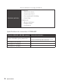
MSI 7C71 Bedienungsanleitung
- Kategorie
- Motherboards
- Typ
- Bedienungsanleitung
- Dieses Handbuch eignet sich auch für
in anderen Sprachen
- français: MSI 7C71 Le manuel du propriétaire
Verwandte Artikel
-
MSI MS-7C73 Bedienungsanleitung
-
MSI Z490-A PRO Bedienungsanleitung
-
MSI MEG Z490 GODLIKE Bedienungsanleitung
-
MSI MEG Z590 ACE GOLD EDITION Bedienungsanleitung
-
-
MSI MPG Z490M GAMING EDGE WIFI Bedienungsanleitung
-
MSI MPG Z590 GAMING FORCE Bedienungsanleitung
-
MSI MS-7C80 Bedienungsanleitung
-
MSI MPG Z490 GAMING EDGE WIFI Bedienungsanleitung