
EN
English - Instruction manual
IT
Italiano - Manuale di istruzioni
FR
Français - Manuel d’instructions
DE
Deutsch - Bedienungsanleitung
RU
Русский - Руководство по эксплуатации
РУССКИЙ
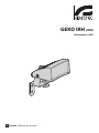
GEKO IRH (IRH)
LED illuminator


EN
English - Instruction manual
ENGLISH
GEKO IRH (IRH)
LED illuminator

Contents
ENGLISH 1
1 About this manual ....................................................................................................................3
1.1 Typographical conventions ................................................................................................................................................ 3
2 Notes on copyright and information on trademarks .............................................................3
3 Safety rules................................................................................................................................3
4 Identification .............................................................................................................................5
4.1 Product description and type designation ................................................................................................................... 5
4.2 Product marking ..................................................................................................................................................................... 5
5 Preparing the product for use .................................................................................................5
5.1 Unpacking ................................................................................................................................................................................. 5
5.2 Contents .................................................................................................................................................................................... 5
5.3 Safely disposing of packaging material ......................................................................................................................... 5
6 Assembly ................................................................................................................................... 6
7 Installation ................................................................................................................................6
7.1 Installation of wall-mounted illuminator ....................................................................................................................... 6
7.2 Installation of housing-fitted illuminator (OSUPPIR kit) ........................................................................................... 7
7.3 Connections ............................................................................................................................................................................. 7
7.4 Twilight sensor activation threshold adjustment ....................................................................................................... 7
7.5 Disabling the twilight sensor ............................................................................................................................................. 8
7.6 Power and control cable ...................................................................................................................................................... 8
7.7 Cable technical specifications ............................................................................................................................................ 8
8 Information on disposal and recycling ................................................................................... 9
9 Troubleshooting .......................................................................................................................9
9.1 Checking the power supply ................................................................................................................................................ 9
9.2 Check operation of the twilight sensor .......................................................................................................................... 9
10 Technical data .........................................................................................................................9
10.1 General .................................................................................................................................................................................... 9
10.2 Mechanical ............................................................................................................................................................................. 9
10.3 Electrical .................................................................................................................................................................................. 9
10.4 Illuminators ............................................................................................................................................................................ 9
10.5 Environment ........................................................................................................................................................................10
10.6 Certifications ........................................................................................................................................................................10
11 Technical drawings ...............................................................................................................10

Instruction manual - English - EN
3MNVCIRHS_2222_EN
1 About this manual
Read all the documentation supplied carefully before
installing and using this product. Keep the manual in
a convenient place for future reference.
1.1 Typographical conventions
DANGER!
Emission of visible light or infrared.
Can be harmful for eyes. Pay attention to
the provided indications.
DANGER!
High level hazard.
Risk of electric shock. Disconnect the
power supply before proceeding with any
operation, unless indicated otherwise.
DANGER!
Hot surface.
Avoid contact. Surfaces are hot and may
cause personal injury if touched.
CAUTION!
Medium level hazard.
This operation is very important for the
system to function properly. Please read
the procedure described very carefully and
carry it out as instructed.
INFO
Description of system specifications.
We recommend reading this part carefully
in order to understand the subsequent
stages.
2 Notes on copyright and
information on trademarks
The mentioned names of products or companies are
trademarks or registered trademarks.
3 Safety rules
Do not stare at the lamp when on. Can be
harmful for eyes.
The infrared LED illuminator emits high-
intensity visible light. In compliance
with standard EN62471/IEC62471, the
photobiological safety assessment has
classified the device in Risk Group 1, where
it exceeds the values of the Exempt Group.
The risk linked to the observer depends
on how the product has been installed
and is used. For installation, follow the
instructions in this manual. Do not open
the illuminator for whatever reason. Do not
look directly at the illuminator using optical
lenses. Exposure hazard values (EHV):
170.2s (for models IRH10H8A, IRH10L8A,
IRH30H8A, IRH30L8A, IRH60H8A,
IRH60L8A), 153.2s (for models IRH10H9A
IRH30H9A IRH60H9A). Hazard distance
(HD): 200mm.
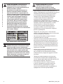
Fig. 1 Infrared illuminator.
RISK GROUP 1
CAUTION: IR emitted
from this product.
Use appropriate
shielding or eye
protection.
ATTENTION: IR sont
émis par ce produit.
Utiliser un blindage
approprié ou une
protection oculaire.
GROUPE DE RISQUE 1

EN - English - Instruction manual
4 MNVCIRHS_2222_EN
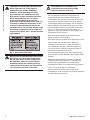
CAUTION! The white light LED illuminator
emits high-intensity visible light. In
compliance with standard EN62471/
IEC62471, the photobiological safety
assessment has classified the device in
Risk Group 2, where it exceeds the values
of the Exempt Group. The risk linked
to the observer depends on how the
product has been installed and is used. For
installation, follow the instructions in this
manual. Do not open the illuminator for
whatever reason. Do not look directly at the
illuminator using optical lenses. Exposure
hazard values (EHV): 24.3s. Hazard distance
(HD): 200mm.
Fig. 2 White light illuminator.
During normal operation the surface of the
illuminator can reach high temperatures.
Do not allow direct contact and position
the appliance where it is inaccessible to
unauthorised persons. Before touching
switch off the illuminator and allow to cool
for a minimum period of 10 minutes.
CAUTION! Device installation and
maintaining must be performed by
specialist technical staff only.
• The manufacturer declines all responsibility
for any damage caused by an improper use
of the appliances mentioned in this manual.
Furthermore, the manufacturer reserves the right
to modify its contents without any prior notice.
The documentation contained in this manual has
been collected and verified with great care. The
manufacturer, however, cannot take any liability
for its use. The same thing can be said for any
person or company involved in the creation and
production of this manual.
• Before starting any operation, make sure the
power supply is disconnected.
• Be careful not to use cables that seem worn or old.
• Never, under any circumstances, make any
changes or connections that are not shown in
this handbook. Improper use of the appliance
can cause serious hazards, risking the safety of
personnel and of the installation.
• Use only original spare parts. Non-original spare
parts could cause fire, electrical discharge or other
hazards.
• Before proceeding with installation, check the
supplied material to make sure it corresponds
to the order specification by examining the
identification labels (4.2 Product marking, page 5).
• This is a Class A product. In a domestic
environment this product may cause radio
interference. In this case the user may be required
to take adequate measures.

Instruction manual - English - EN
5MNVCIRHS_2222_EN
4 Identification
4.1 Product description and type
designation
The GEKO lights the entire scene evenly, eliminating
hotspots and underexposures, for unbeatable night-
time images and secure surveillance of the area.
The high efficiency heat sink body ensures
maximum LED durability and protection against
over-temperatures, whereas the front glass, made
of special technopolymer, provides high infrared
transmittance.
The GEKO illuminators are protected against
electrostatic discharges.
The illuminators can be powered at 12Vdc to 24Vdc
or at 24Vac.
The power supply in a waterproof box, in 230Vac or
120Vac version, is available as an accessory for one or
two GEKO illuminators.
GEKO is supplied with a wall-mount bracket that
rotates horizontally and vertically and can be
assembled in a housing by means of the OSUPPIR
bracket.
The GEKO infrared illuminator guarantee is 5 years,
while for GEKO with the white light is 2 years.
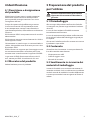
4.2 Product marking
See the label attached to the product.
5 Preparing the product for
use
Any change that is not expressly approved
by the manufacturer will invalidate the
guarantee.
5.1 Unpacking
When the product is delivered, make sure that the
package is intact and that there are no signs that it
has been dropped or scratched.
If there are obvious signs of damage, contact the
supplier immediately.
When returning a faulty product we recommend
using the original packaging for shipping.
Keep the packaging in case you need to send the
product for repairs.
5.2 Contents
Check the contents to make sure they correspond
with the list of materials as below:
• Illuminator with bracket
• Wall-fastening bracket
• Instruction manual
5.3 Safely disposing of packaging
material
The packaging material can all be recycled. The
installer technician will be responsible for separating
the material for disposal, and in any case for
compliance with the legislation in force where the
device is to be used.

EN - English - Instruction manual
6 MNVCIRHS_2222_EN
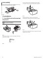
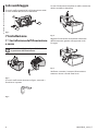
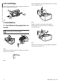
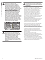
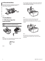
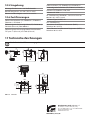
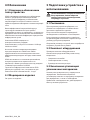
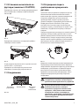
6 Assembly
Fasten the top bracket (01) to the illuminator using
the screws and washers (02) supplied.
01
02
02
Fig. 3
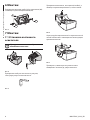
7 Installation
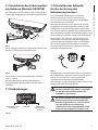
7.1 Installation of wall-mounted
illuminator
The illuminator’s position can be decided at
the time of installation.
Fig. 4
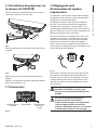
Fasten the bracket as shown in the figure. Drive the
wall screws in tight.
Fig. 5
Fasten the illuminator, complete with its bracket,
using the screw, the nut and the washer supplied.
Fig. 6
Set the illuminator’s vertical and horizontal
inclination by adjusting the two fastening screws.
Fig. 7
Check the resulting illumination range on the screen.
Tighten all the screws.

Instruction manual - English - EN
7MNVCIRHS_2222_EN
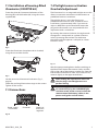
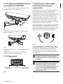
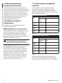
7.2 Installation of housing-fitted
illuminator (OSUPPIR kit)
Fasten the plate (01) between the bottom of the
housing (02) and the bracket (03) using the screws
supplied (04).
02
01
04
03
Fig. 8
Fasten the illuminator (complete with its bracket)
using the nut and the washer.
Fig. 9
Set the vertical and horizontal inclination (Fig. 7,
page 6).
Check the resulting illumination range on the screen.
Tighten all the screws.
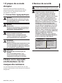
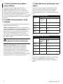
7.3 Connections
Power supply
and control Photocell Switch-on
threshold
regulator
Fig. 10
7.4 Twilight sensor activation
threshold adjustment
The illuminator has an integrated twilight sensor that
allows its automatic activation and deactivation at
predefined luminous conditions.
The twilight sensor is set in the factory at a
predetermined luminous level, suitable for most
installations (approximately 50lx). If you want to
adjust in different ways the threshold, loosen the
plug on the illuminator rear and proceed for the
adjustment with a screwdriver.
By rotating the trimmer clockwise, the night mode
changeover is anticipated (at a greater luminous
value). By rotating the trimmer anti-clockwise,
the night mode changeover is delayed (at a lower
luminous value).
Fig. 11
Wait for appropriate brightness before switching on
the illuminator. Rotate the trimmer slowly until the
LED on the side of the trimmer switches on. Once the
intervention threshold has been surpassed (LED on),
rotate it slightly in the opposite direction.
After making the adjustments make sure
that the plug is closed tight to ensure
perfect sealing.
When setting the illuminator to be switched
on automatically by the embedded light
sensitive switch, make sure to insulate the
remote control (telemetry) cables in the
power cord (green and red colors).

EN - English - Instruction manual
8 MNVCIRHS_2222_EN
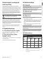
7.5 Disabling the twilight sensor
To disable the lamp’s automatic switch-on set the
brightness to minimum (turn the potentiometer all
the way anticlockwise). With this setting the lamp can
only be switched on by closing the telemetry contact,
if the system is equipped with a central light sensitive
switch or a remote-controlled contact.
7.6 Power and control cable
The illuminator is supplied with a 2m (6.6ft) long
power and control cord.
Power supply cables (white, black): The illuminator
can be powered either by 24Vac/Vdc or 12Vdc.
Provide power to the black and white cable pair
(white, black, the polarity is irrelevant). For proper
operation please refer to the charts, taking into
account the power supply and the type of illuminator
installed (7.7 Cable technical specifications, page 8).
To avoid product malfunctions connect
2 illuminators maximum for each power
supply.
Remote control (telemetry) cables, green and
red colors: The control cable (telemetry) lets you
turn on the illuminator remotely by means of a dry
contact applied between the ends of the green and
red cables. For proper operation, make sure that
the photocell is disabled (7.5 Disabling the twilight
sensor, page 8). Close the contact to turn on the
illuminator. Open the contact to turn it off.
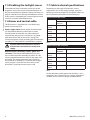
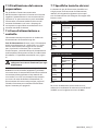
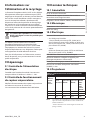
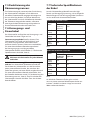
7.7 Cable technical specifications
Depending on the type of illuminator (Low or
High Power) and on the supply voltage, apply the
following maximum lengths for the power cables (to
be connected to the black and white wire pair).
CABLES SPECIFICATIONS 12VDC
Cable section Maximum length
Low Power
illuminator
High Power illuminator
0.5mm²
(20AWG)
10m (32.8ft) 6m (19.7ft)
0.75mm²
(18AWG)
16m (52ft) 9m (29.5ft)
1mm²
(17AWG)
22m (72.2ft) 12m (39ft)
1.5mm²
(16AWG)
32m (105ft) 18m (59.1ft)
Tab. 1
CABLES SPECIFICATIONS 24VAC/VDC
Cable section Maximum length
Low Power
illuminator
High Power illuminator
0.34mm²
(22AWG)
25m (82ft) 15m (49.2ft)
0.5mm²
(20AWG)
40m (131ft) 22m (72.2ft)
0.75mm²
(18AWG)
60m (197ft) 35m (114ft)
1.5mm²
(16AWG)
120m (393ft) 70m (229ft)
Tab. 2
For the telemetry cable (green and red colors), use a
conductor with a minimum cross-section of 0.34mm²
(22AWG) and a maximum length of 200m (656ft).

Instruction manual - English - EN
9MNVCIRHS_2222_EN
8 Information on disposal
and recycling
The European Directive 2012/19/EU on Waste
Electrical and Electronic Equipment (WEEE) mandates
that these devices should not be disposed of in the
normal flow of municipal solid waste, but they should
be collected separately in order to optimize the
recovery stream and recycling of the materials that
they contain and to reduce the impact on human
health and the environment due to the presence of
potentially hazardous substances.
The symbol of the crossed out bin is marked
on all products to remember this.
The waste may be delivered to appropriate collection
centers, or may be delivered free of charge to the
distributor where you purchased the equipment at
the time of purchase of a new equivalent or without
obligation to a new purchase for equipment with size
smaller than 25cm (9.8in).
For more information on proper disposal of these
devices, you can contact the responsible public
service.
9 Troubleshooting
9.1 Checking the power supply
Check that the unit is supplied with a voltage
between 12-24Vdc or 24Vac +/- 10%.
9.2 Check operation of the
twilight sensor
Check operation of the twilight sensor by darkening
it with black tape.
Leave the telemetry connection open.
10 Technical data
10.1 General
Die cast aluminum body
Supplied complete with horizontal and vertical
rotating support in painted galvanized steel
Wavelengths: 850nm, 940nm, white light
10.2 Mechanical
Dimensions: 133x112x135mm (5.2x4.4x5.3in)
Unit weight: 0.9kg (2lb)
10.3 Electrical
Supply voltage/Current consumption:
• from 12Vdc up to 24Vdc:
1A max (high power 4 LED, 12Vdc), 0.5A max (high
power 4 LED, 24Vdc) or 0.5A max (low power 2
LED, 12Vdc), 0.25A max (low power 2 LED, 24Vdc)
• 24Vac:
0.5A max (high power, 4 LED) or 0.25A max (low
power, 2 LED), 50/60Hz
State of the art SMD LED
Adjustable built-in photocell for automatic activation
and deactivation
Input for activation by means of external dry contact
Supplied with multipole cable: 4x0.34mm² (22AWG),
L=2m
10.4 Illuminators
GEKO IRH BEAM PATTERN AND ACHIEVABLE DISTANCES FOR ONE
ILLUMINATOR
Horizon-
tal and
vertical
beam
patterns
Maximum distance
850nm,
low
power
850nm,
high
power
940nm,
high
power
White
light,
high
power
10˚ 100m
(328ft)
140m
(460ft)
100m
(328ft)
–
30˚ 60m (197ft) 84m (276ft) 60m (197ft) 60m
(197ft)¹
60˚ 40m (131ft) 56m (184ft) 40m (131ft) 40m
(131ft)¹
Tab. 3 The distances and the performance depend on the
camera/lens used and on the environmental light
conditions.
¹ Achievable distances with camera in Day mode
(colour image)

MNVCIRHS_2222_EN
10.5 Environment
For indoors and outdoors installation
Operating temperature: from -40°C (-40°F) up to
+60°C (140°F)
Relative humidity: from 5% up to 95%
10.6 Certifications
Electrical safety (CE): EN60950-1, IEC60950-1,
EN62368-1, IEC62368-1
Electromagnetic compatibility (CE): EN50130-4,
EN55032 (Class A), EN61000-6-4
Electromagnetic compatibility (North America): FCC
part 15 (Class A), ICES-003 (Class A)
Outdoor installation (CE): EN60950-22, IEC60950-22
Photobiological safety (CE): EN62471, IEC62471
IP protection degree (EN60529): IP66, IP67
IK protection degree : IK10
UL certification (UL60950-1, CAN/CSA C22.2 No.
60950-1-07): cULus Listed
Level of protection Type (UL50E): 4X
EAC certification
Restriction of Hazardous Substances (RoHS), Directive
2011/65/EU
Waste Electrical and Electronic Equipment (WEEE),
Directive 2012/19/EU
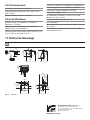
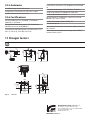
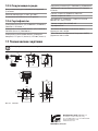
11 Technical drawings
The indicated measurements are expressed in millimetres.
85
65
50
112
133
104
101
104 20
60
80
135
124
133
65
108
Ø 6.2
Ø 8.5
3
144 104
30
48
150°
20°
1825
60
Ø 8.5
Fig. 12 GEKO IRH.
Headquarters Italy Videotec s.r.l.
Via Friuli, 6 - I-36015 Schio (VI) - Italy
Tel. +39 0445 697411 - Fax +39 0445 697414
Email: [email protected]
www.videotec.com

IT
Italiano - Manuale di istruzioni
ITALIANO
GEKO IRH (IRH)
Illuminatore a LED

Sommario
ITALIANO 1
1 Informazioni sul presente manuale ........................................................................................3
1.1 Convenzioni tipografiche .................................................................................................................................................... 3
2 Note sul copyright e informazioni sui marchi commerciali ...................................................3
3 Norme di sicurezza ...................................................................................................................3
4 Identificazione ..........................................................................................................................5
4.1 Descrizione e designazione del prodotto ..................................................................................................................... 5
4.2 Marcatura del prodotto ........................................................................................................................................................ 5
5 Preparazione del prodotto per l'utilizzo .................................................................................5
5.1 Disimballaggio ........................................................................................................................................................................ 5
5.2 Contenuto ................................................................................................................................................................................. 5
5.3 Smaltimento in sicurezza dei materiali di imballaggio ............................................................................................. 5
6 Assemblaggio ...........................................................................................................................6
7 Installazione ..............................................................................................................................6
7.1 Installazione dell'illuminatore a muro ............................................................................................................................ 6
7.2 Installazione dell'illuminatore su custodia (kit OSUPPIR) ........................................................................................ 7
7.3 Collegamenti ............................................................................................................................................................................ 7
7.4 Regolazione della soglia di intervento del sensore crepuscolare ......................................................................... 7
7.5 Disattivazione del sensore crepuscolare ........................................................................................................................ 8
7.6 Cavo di alimentazione e controllo.................................................................................................................................... 8
7.7 Specifiche tecniche dei cavi................................................................................................................................................ 8
8 Informazioni sullo smaltimento e il riciclo .............................................................................9
9 Risoluzione dei problemi ......................................................................................................... 9
9.1 Controllo dell’alimentazione elettrica ............................................................................................................................ 9
9.2 Verifica della funzionalità del sensore crepuscolare .................................................................................................. 9
10 Dati tecnici ..............................................................................................................................9
10.1 Generale .................................................................................................................................................................................. 9
10.2 Meccanica ............................................................................................................................................................................... 9
10.3 Elettrico.................................................................................................................................................................................... 9
10.4 Illuminatori ............................................................................................................................................................................. 9
10.5 Ambiente ..............................................................................................................................................................................10
10.6 Certificazioni ........................................................................................................................................................................ 10
11 Disegni tecnici ......................................................................................................................10

Manuale di istruzioni - Italiano - IT
3MNVCIRHS_2222_IT
1 Informazioni sul presente
manuale
Prima di installare e utilizzare questo prodotto,
leggere attentamente tutta la documentazione
fornita. Tenere il manuale a portata di mano per
consultazioni successive.
1.1 Convenzioni tipografiche
PERICOLO!
Emissione di luce visibile o infrarossa.
Può essere dannoso per gli occhi. Prestare
attenzione alle indicazioni fornite.
PERICOLO!
Pericolosità elevata.
Rischio di scosse elettriche. Prima di
eseguire qualsiasi operazione assicurarsi di
togliere tensione al prodotto, salvo diversa
indicazione.
PERICOLO!
Superficie calda.
Evitare il contatto. Le superfici sono calde
e potrebbero causare danni alla persona in
caso di contatto.
ATTENZIONE!
Pericolosità media.
L'operazione è molto importante per il
corretto funzionamento del sistema. Si
prega di leggere attentamente la procedura
indicata e di eseguirla secondo le modalità
previste.
INFO
Descrizione delle caratteristiche del
sistema.
Si consiglia di leggere attentamente per
comprendere le fasi successive.
2 Note sul copyright e
informazioni sui marchi
commerciali
I nomi di prodotto o di aziende citati sono marchi
commerciali o marchi commerciali registrati
appartenenti alle rispettive società.
3 Norme di sicurezza
Non fissare la lampada in funzione. Può
essere dannoso per gli occhi.
L’illuminatore a LED a luce infrarossa
emette luce ad alta intensità visibile. La
valutazione foto-biologica di sicurezza,
in accordo con la norma EN62471/
IEC62471, ha portato alla classificazione del
dispositivo nel Gruppo di Rischio 1, dove
si superano i valori del Gruppo Esente. Il
rischio correlato all’osservatore dipende
da come gli utenti installano e utilizzano
il prodotto. Per l'installazione seguire le
istruzioni contenute in questo manuale.
Non aprire l'illuminatore per qualsiasi
motivo. Non guardare l'illuminatore
direttamente utilizzando strumenti ottici.
Valori di esposizione pericolosa (EHV):
170.2s (per i modelli IRH10H8A, IRH10L8A,
IRH30H8A, IRH30L8A, IRH60H8A,
IRH60L8A), 153.2s (per i modelli IRH10H9A
IRH30H9A IRH60H9A). Distanze di pericolo
(HD): 200mm.
Fig. 1 Illuminatore infrarosso.
RISK GROUP 1
CAUTION: IR emitted
from this product.
Use appropriate
shielding or eye
protection.
ATTENTION: IR sont
émis par ce produit.
Utiliser un blindage
approprié ou une
protection oculaire.
GROUPE DE RISQUE 1

IT - Italiano - Manuale di istruzioni
4 MNVCIRHS_2222_IT
ATTENZIONE! L’illuminatore a LED a luce
bianca emette luce ad alta intensità visibile.
La valutazione foto-biologica di sicurezza,
in accordo con la norma EN62471/
IEC62471, ha portato alla classificazione del
dispositivo nel Gruppo di Rischio 2, dove
si superano i valori del Gruppo Esente. Il
rischio correlato all’osservatore dipende
da come gli utenti installano e utilizzano
il prodotto. Per l'installazione seguire le
istruzioni contenute in questo manuale.
Non aprire l'illuminatore per qualsiasi
motivo. Non guardare l'illuminatore
direttamente utilizzando strumenti ottici.
Valori di esposizione pericolosa (EHV):
24.3s. Distanze di pericolo (HD): 200mm.
Fig. 2 Illuminatore a luce bianca.
Durante il normale funzionamento
la superficie dell'illuminatore può
raggiungere temperature elevate.
Evitare il contatto diretto e posizionare
l’apparecchiatura in luogo non accessibile
al personale non autorizzato. Per
qualunque operazione di manutenzione
spegnere il dispositivo d’illuminazione e
lasciarlo raffreddare per almeno 10 minuti.
ATTENZIONE! L'installazione e la
manutenzione del dispositivo devono
essere eseguite solo da personale tecnico
specializzato.
• Il produttore declina ogni responsabilità per
eventuali danni derivanti da un uso improprio
delle apparecchiature menzionate in questo
manuale. Si riserva inoltre il diritto di modificarne il
contenuto senza preavviso. Ogni cura è stata posta
nella raccolta e nella verifica della documentazione
contenuta in questo manuale. Il produttore,
tuttavia, non può assumersi alcuna responsabilità
derivante dall'utilizzo della stessa. Lo stesso
dicasi per ogni persona o società coinvolta nella
creazione e nella produzione di questo manuale.
• Prima di eseguire qualsiasi operazione assicurarsi
di togliere tensione al prodotto.
• Non utilizzare cavi con segni di usura o
invecchiamento.
• Non effettuare per nessun motivo alterazioni o
collegamenti non previsti in questo manuale.
L'uso di apparecchi non idonei può portare a
gravi pericoli per la sicurezza del personale e
dell'impianto.
• Utilizzare solo parti di ricambio originali. Pezzi di
ricambio non originali potrebbero causare incendi,
scariche elettriche o altri pericoli.
• Prima di procedere con l'installazione, controllare
che il materiale fornito corrisponda alle specifiche
richieste esaminando le etichette di marcatura (4.2
Marcatura del prodotto, pagina 5).
• Questo è un prodotto di Classe A. In un ambiente
residenziale questo prodotto può provocare
radiodisturbi. In questo caso può essere richiesto
all'utilizzatore di prendere misure adeguate.

Manuale di istruzioni - Italiano - IT
5MNVCIRHS_2222_IT
4 Identificazione
4.1 Descrizione e designazione
del prodotto
GEKO illumina l’intera scena in modo omogeneo
eliminando macchie di luce e sottoesposizioni
per insuperabili immagini notturne e una sicura
sorveglianza dell’area.
Il corpo dissipatore ad alta efficienza garantisce
la massima durata dei LED e protezione contro
le sovratemperature, mentre il vetro frontale, in
speciale tecnopolimero, offre un’elevata trasmittanza
infrarossa.
Gli illuminatori GEKO sono protetti contro le scariche
elettrostatiche.
Gli illuminatori possono essere alimentati da 12Vdc a
24Vdc oppure in 24Vac.
L'alimentatore in scatola stagna, in versione 230Vac o
120Vac, è disponibile come accessorio per uno o due
illuminatori GEKO.
GEKO é fornito con supporto per il montaggio a muro
con rotazione orizzontale e verticale e può essere
montato sotto custodia tramite il supporto OSUPPIR.
La garanzia di GEKO illuminatore infrarosso é di 5
anni, mentre per GEKO a luce bianca é di 2 anni.
4.2 Marcatura del prodotto
Vedere l’etichetta posta sul prodotto.
5 Preparazione del prodotto
per l'utilizzo
Qualsiasi intervento non espressamente
approvato dal costruttore fa decadere la
garanzia.
5.1 Disimballaggio
Alla consegna del prodotto verificare che l'imballo
sia integro e non presenti segni evidenti di cadute o
abrasioni.
In caso di danni evidenti all'imballo contattare
immediatamente il fornitore.
In caso di restituzione del prodotto malfunzionante
è consigliato l'utilizzo dell'imballaggio originale per
il trasporto.
Conservare l'imballo qualora fosse necessario inviare
il prodotto in riparazione.
5.2 Contenuto
Controllare che il contenuto sia corrispondente alla
lista del materiale sotto elencato:
• Illuminatore con staffa
• Staffa fissaggio a muro
• Manuale di istruzioni
5.3 Smaltimento in sicurezza dei
materiali di imballaggio
I materiali d'imballo sono costituiti interamente da
materiale riciclabile. Sarà cura del tecnico installatore
smaltirli secondo le modalità di raccolta differenziata
o comunque secondo le norme vigenti nel Paese di
utilizzo.

IT - Italiano - Manuale di istruzioni
6 MNVCIRHS_2222_IT
6 Assemblaggio
Fissare la staffa superiore (01) all'illuminatore tramite
le viti e rondelle (02) fornite in dotazione.
01
02
02
Fig. 3
7 Installazione
7.1 Installazione dell'illuminatore
a muro
In fase di installazione è possibile decidere
la posizione dell'illuminatore.
Fig. 4
Fissare la staffa come descritto in figura, serrando a
fondo le viti a parete.
Fig. 5
Fissare l'illuminatore completo di staffa tramite vite,
dado e rondelle in dotazione.
Fig. 6
Regolare l'inclinazione verticale ed orizzontale
dell'illuminatore agendo sulle apposite viti di
fissaggio.
Fig. 7
Verificare a monitor il campo di illuminazione
ottenuto. Serrare a fondo tutte le viti.

Manuale di istruzioni - Italiano - IT
7MNVCIRHS_2222_IT
7.2 Installazione dell'illuminatore
su custodia (kit OSUPPIR)
Fissare la piastra (01) tra fondo custodia (02) e staffa
(03) tramite le viti in dotazione (04).
02
01
04
03
Fig. 8
Fissare l'illuminatore completo di staffa tramite il
dado e la rondella.
Fig. 9
Regolare l'inclinazione verticale ed orizzontale (Fig.
7, pagina 6).
Verificare a monitor il campo di illuminazione
ottenuto. Serrare a fondo tutte le viti.
7.3 Collegamenti
Alimentazione
e controllo Fotocellula Regolatore so-
glia accensione
Fig. 10
7.4 Regolazione della soglia
di intervento del sensore
crepuscolare
L'illuminatore ha un sensore crepuscolare integrato
che consente l'accensione e lo spegnimento
automatico a condizioni luminose prestabilite.
La regolazione del sensore crepuscolare è effettuata
in fabbrica ad un livello luminoso prefissato ed
idoneo alla maggior parte delle installazioni (circa
50lx). Nel caso si voglia regolare in maniera diversa
la soglia di intervento, svitare il tappo in metallo
posizionato sul retro dell'illuminatore e provvedere
alla regolazione tramite un cacciavite.
Ruotando il trimmer in senso orario la commutazione
in modalità notturna è anticipata (ad un valore di
luminosità maggiore). Ruotando il trimmer in senso
antiorario la commutazione in modalità notturna è
ritardata (ad un valore di luminosità inferiore).
Fig. 11
Attendere le condizioni di luminosità adeguate per
l'accensione dell'illuminatore. Ruotare lentamente
il trimmer fino all'accensione del LED presente a
lato del trimmer. Una volta oltrepassata la soglia
di intervento (LED acceso), ruotare leggermente in
senso opposto.
Al termine delle regolazioni accertarsi che
il tappo di chiusura sia adeguatamente
serrato per garantire la tenuta ermetica del
prodotto.
Nel caso di utilizzo dell’accensione
automatica dell'illuminatore mediante
interruttore crepuscolare incorporato,
assicurarsi di isolare opportunamente i cavi
relativi al controllo remoto (Telemetria)
presenti nel cordone di alimentazione
(colori verde e rosso).

IT - Italiano - Manuale di istruzioni
8 MNVCIRHS_2222_IT
7.5 Disattivazione del sensore
crepuscolare
Per disabilitare l’accensione automatica
dell'illuminatore impostare la luminosità al minimo
(regolare il potenziometro in senso antiorario fino
a finecorsa). In questa maniera si potrà accendere
l'illuminatore solamente mediante chiusura del
contatto di telemetria, nel caso si disponga di
un impianto a crepuscolare centralizzato o di un
contatto attivabile da remoto.
7.6 Cavo di alimentazione e
controllo
L'illuminatore viene provvisto con un cordone di
alimentazione e di controllo lungo 2m.
Cavi di alimentazione (bianco, nero): L'illuminatore
può essere alimentato sia a 24Vac/Vdc sia a 12Vdc.
Fornire alimentazione alla coppia di cavi (bianco,
nero, la polarità è irrilevante). Per un corretto
funzionamento, a seconda del tipo di alimentazione
e del modello di illuminatore scelto, fare riferimento
alle tabelle (7.7 Specifiche tecniche dei cavi, pagina
8).
Per evitare malfunzionamenti del prodotto
collegare al massimo 2 illuminatori per ogni
alimentatore.
Cavi di controllo remoto (telemetria), colori verde
e rosso: Il cavo di controllo (telemetria), permette
una accensione da remoto dell'illuminatore mediante
un contatto pulito applicato tra le estremità dei
cavi verde e rosso. Per un corretto funzionamento,
assicurarsi di avere disabilitato la fotocellula (7.5
Disattivazione del sensore crepuscolare, pagina 8).
Chiudere il contatto per accendere l'illuminatore.
Aprire il contatto per spegnerlo.
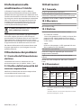
7.7 Specifiche tecniche dei cavi
In relazione al tipo di illuminatore (modello Low
o High power) e alla tensione di alimentazione,
attenersi alle seguenti lunghezze massime per i
cavi di alimentazione (da collegare alla coppia di fili
bianco e nero).
SPECIFICHE DEI CAVI 12VDC
Sezione del
cavo
Lunghezza massima
Illuminatore
versione Low
Power
Illuminatore versione High
Power
0.5mm²
(20AWG)
10m 6m
0.75mm²
(18AWG)
16m 9m
1mm²
(17AWG)
22m 12m
1.5mm²
(16AWG)
32m 18m
Tab. 1
SPECIFICHE DEI CAVI 24VAC/VDC
Sezione del
cavo
Lunghezza massima
Illuminatore
versione Low
Power
Illuminatore versione High
Power
0.34mm²
(22AWG)
25m 15m
0.5mm²
(20AWG)
40m 22m
0.75mm²
(18AWG)
60m 35m
1.5mm²
(16AWG)
120m 70m
Tab. 2
Per il cavo di telemetria (colori verde e rosso),
utilizzare un conduttore di sezione minima 0,34mm²
(22AWG) e una lunghezza massima di 200m.
Seite wird geladen ...
Seite wird geladen ...
Seite wird geladen ...
Seite wird geladen ...
Seite wird geladen ...
Seite wird geladen ...
Seite wird geladen ...
Seite wird geladen ...
Seite wird geladen ...
Seite wird geladen ...
Seite wird geladen ...
Seite wird geladen ...
Seite wird geladen ...
Seite wird geladen ...
Seite wird geladen ...
Seite wird geladen ...
Seite wird geladen ...
Seite wird geladen ...
Seite wird geladen ...
Seite wird geladen ...
Seite wird geladen ...
Seite wird geladen ...
Seite wird geladen ...
Seite wird geladen ...
Seite wird geladen ...
Seite wird geladen ...
Seite wird geladen ...
Seite wird geladen ...
Seite wird geladen ...
Seite wird geladen ...
Seite wird geladen ...
Seite wird geladen ...
Seite wird geladen ...
Seite wird geladen ...
-
 1
1
-
 2
2
-
 3
3
-
 4
4
-
 5
5
-
 6
6
-
 7
7
-
 8
8
-
 9
9
-
 10
10
-
 11
11
-
 12
12
-
 13
13
-
 14
14
-
 15
15
-
 16
16
-
 17
17
-
 18
18
-
 19
19
-
 20
20
-
 21
21
-
 22
22
-
 23
23
-
 24
24
-
 25
25
-
 26
26
-
 27
27
-
 28
28
-
 29
29
-
 30
30
-
 31
31
-
 32
32
-
 33
33
-
 34
34
-
 35
35
-
 36
36
-
 37
37
-
 38
38
-
 39
39
-
 40
40
-
 41
41
-
 42
42
-
 43
43
-
 44
44
-
 45
45
-
 46
46
-
 47
47
-
 48
48
-
 49
49
-
 50
50
-
 51
51
-
 52
52
-
 53
53
-
 54
54


in anderen Sprachen
- français: Videotec GEKO IRH Manuel utilisateur
- italiano: Videotec GEKO IRH Manuale utente