Baumer HOG 22 Installation and Operating Instructions
- Typ
- Installation and Operating Instructions

MB049 - 11114026
Baumer_HOG22_II_DE-EN (20A1)
Montage- und Betriebsanleitung
Mounting and operating instructions
HOG 22
Inkrementaler Drehgeber
Incremental encoder
Option M:
redundant
Option M:
redundant

Inhaltsverzeichnis
Baumer_HOG22_II_DE-EN (20A1)
MB049 - 11114026
Inhaltsverzeichnis
1 Allgemeine Hinweise 1
2 Betrieb in explosionsgefährdeten Be-
reichen
3
3 Sicherheitshinweise
5
4 Vorbereitung
7
4.1 Lieferumfang
7
4.1.1 Mit Klemmenkasten
7
4.1.2 Mit Einschubelektronik und
Winkel-Flanschdose
8
4.2 Zur Montage erforderlich
(nicht im Lieferumfang enthalten)
9
4.3 Erforderliches Werkzeug
(nicht im Lieferumfang enthalten)
9
5 Montage
10
5.1 Schritt 1
10
5.2 Schritt 2
10
5.3 Schritt 3
11
5.4 Montage der Drehmomentstütze
12
5.5 Hinweis zur Vermeidung von
Messfehlern
13
5.6 Schritt 5
14
5.7 Montagehinweis
14
6 Abmessungen
15
6.1 Mit Klemmenkasten
15
6.2 Mit Einschubelektronik und Winkel-
Flanschdose
16
7 Elektrischer Anschluss
17
7.1 Beschreibung der Anschlüsse
17
7.2 Ausgangssignale
17
7.3 Mit Klemmenkasten
18
7.3.1 Kabelanschluss
18
7.3.1.1 Step 1
18
7.3.1.2 Step 2 and 3
18
7.3.1.3 Step 4
19
7.3.1.4 Step 5
19
7.3.1.5 Step 6
20
7.3.2 Klemmenbelegung
Klemmenkasten
21
7.4 Mit Einschubelektronik und Winkel-
Flanschdose
22
7.4.1 Kabelanschluss
22
7.4.1.1 Step 1
22
7.4.1.2 Step 2
23
7.4.1.3 Step 3
23
7.4.2 Pinbelegung Winkel-Flanschdose
24
7.5 Sensorkabel HEK 8 (Zubehör)
24
8 Demontage
25
8.1 Schritt 1 und 2 - Klemmenkasten
25
8.2 Schritt 1 und 2 - Rundsteckverbinder
25
8.3 Schritt 3
26
8.4 Schritt 4
26
8.5 Schritt 5
27
9 Zubehör
28
10 Technische Daten
29
10.1 Technische Daten - elektrisch
29
10.2 Technische Daten - mechanisch
29
11 EU-Konformitätserklärung
31

Table of contens
MB049 - 11114026
Baumer_HOG22_II_DE-EN (20A1)
Table of contents
1 General notes 2
2 Operation in potentially explosive
environments
4
3 Security indications
6
4 Preparation
7
4.1 Scope of delivery
7
4.1.1 With terminal box
7
4.1.2 With plug-in electronics and
angle ange connector
8
4.2 Required for mounting
(not included in scope of delivery)
9
4.3 Required tools
(not included in scope of delivery)
9
5 Mounting
10
5.1 Step 1
10
5.2 Step 2
10
5.3 Step 3
11
5.4 Mounting the torque arm
12
5.5 How to prevent measurement
errors
13
5.6 Step 5
14
5.7 Mounting instruction
14
6 Dimensions
15
6.1 With terminal box
15
6.2 With plug-in electronics and
angle ange connector
16
7 Electrical connection
17
7.1 Terminal signicance
17
7.2 Output signals
17
7.3 With terminal box
18
7.3.1 Cable connection
18
7.3.1.1 Step 1
18
7.3.1.2 Step 2 and 3
18
7.3.1.3 Step 4
19
7.3.1.4 Step 5
19
7.3.1.5 Step 6
20
7.3.2 Terminal assignment
terminal box
21
7.4 With plug-in electronics and
angle ange connector
22
7.4 .1 Cable connection
22
7.4.1.1 Step 1
22
7.4 .1.2 Step 2
23
7.4 .1.3 Step 3
23
7.4 .2 Pin assignment angle ange
connector
24
7.5 Sensor cable HEK 8 (accessory)
24
8 Dismounting
25
8.1 Step 1 und 2 - Terminal box
25
8.2 Step 1 und 2 - Mating connector
25
8.3 Step 3
26
8.4 Step 4
26
8.5 Step 5
27
9 Accessories
28
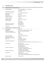
10 Technical data
30
10.1 Technical data - electrical ratings
30
10.2 Technical data - mechanical design
30
11 EU Declaration of Conformity
31

1 Allgemeine Hinweise
1 Baumer_HOG22_II_DE-EN (20A1)
MB049 - 11114026
1 Allgemeine Hinweise
1.1 Zeichenerklärung:
Gefahr
Warnung bei möglichen Gefahren
Hinweis zur Beachtung
Hinweis zur Gewährleistung eines einwandfreien Betriebes des Gerätes
i
Information
Empfehlung für die Gerätehandhabung
1.2 Der inkrementale Drehgeber HOG 22 ist ein opto-elektronisches Prä zi sionsmessgerät, das
mit Sorgfalt nur von technisch qualiziertem Per sonal gehandhabt werden darf.
1.3 Die zu erwartende Lebensdauer des Gerätes hängt von den Kugellagern ab, die mit einer
Dauerschmierung ausgestattet sind.
1.4 Der Lagertemperaturbereich des Gerätes liegt zwischen -15 °C bis +70 °C.
1.5 Der Betriebstemperaturbereich des Gerätes liegt zwischen -30 °C bis +85 °C, eingeschränkt
im Ex-Bereich, siehe Abschnitt 2, am Gehäuse gemessen.
1.6
EU-Konformitätserklärung gemäß den europäischen Richtlinien.
1.7 Das Gerät ist zugelassen nach UL (gilt nicht für Einsatz in explosionsgefährdeten Bereichen).
1.8 Wir gewähren 2 Jahre Gewährleistung im Rahmen der Bedingungen des Zentralverbandes der
Elektroindustrie (ZVEI).
1.9 Wartungsarbeiten sind nicht erforderlich. Das Gerät darf nur wie in dieser Anleitung beschrie-
ben geöffnet werden. Reparaturen, die ein vollständiges Öffnen des Gerätes erfordern, sind
vom Hersteller durchzuführen. Am Gerät dürfen keine Veränderungen vorgenommen werden.
1.10 Bei Rückfragen bzw. Nachlieferungen sind die auf dem Typenschild des Gerätes angege-
benen Daten, insbesondere Typ und Seriennummer, unbedingt anzugeben.
1.11
Entsorgung (Umweltschutz):
Gebrauchte Elektro- und Elektronikgeräte dürfen nicht im Hausmüll entsorgt werden.
Das Produkt enthält wertvolle Rohstoffe, die recycelt werden können. Wenn immer
möglich sollen Altgeräte lokal am entsprechenden Sammeldepot entsorgt werden. Im
Bedarfsfall gibt Baumer den Kunden die Möglichkeit, Baumer-Produkte fachgerecht zu entsor-
gen. Weitere Informationen siehe www.baumer.com.
Achtung!
Beschädigung des auf dem Gerät bendlichen Siegels führt zu Gewährleistungsverlust.

General notes 1
MB049 - 11114026
Baumer_HOG22_II_DE-EN (20A1) 2
1 General notes
1.1 Symbol guide:
Danger
Warnings of possible danger
General information for attention
Informations to ensure correct device operation
i
Information
Recommendation for device handling
1.2 The incremental encoder HOG 22 is an opto electro nic precision measurement device which
must be handled with care by skilled personnel only.
1.3 The expected service life of the device depends on the ball bearings, which are equipped with
a permanent lubrication.
1.4 The storage temperature range of the device is between -15 °C and +70 °C.
1.5 The operating temperature range of the device is between -30 °C and +85 °C, restricted in
potentially explosive environments, see section 2, measured at the housing.
1.6
EU Declaration of Conformity meeting to the European Directives.
1.7 The device is UL approved (not applicable for operation in potentially explosive atmospheres).
1.8 We grant a 2-year warranty in accordance with the regulations of the ZVEI (Central Association
of the German Electrical Industry).
1.9 Maintenance work is not necessary. The device may be only opened as described in this
instruction. Repair work that requires opening the device completely must be carried out by the
manufacturer. Alterations of the device are not permitted.
1.10 In the event of queries or subsequent deliveries, the data on the device type label must be
quoted, especially the type designation and the serial number.
1.11
Disposal (environmental protection):
Do not dispose of electrical and electronic equipment in household waste. The product
contains valuable raw materials for recycling. Whenever possible, waste electrical and
electronic equipment should be disposed locally at the authorized collection point. If
necessary, Baumer gives customers the opportunity to dispose of Baumer products profession-
ally. For further information see www.baumer.com.
Warning!
Damaging the seal on the device invalidates warranty.

2 Betrieb in explosionsgefährdeten Bereichen
3 Baumer_HOG22_II_DE-EN (20A1)
MB049 - 11114026
2 Betrieb in explosionsgefährdeten Bereichen
Das Gerät entspricht den Bauvorschriften der Gerätekategorie 3 G, Gerätegruppe II (Ex-Atmo-
sphäre Gas) und der Gerätekategorie 3 D, Gerätegruppe III (Ex-Atmosphäre Staub).
Richtlinienkonformität gemäß 2014/34/EU.
CE-Kennzeichnung:
Kategorie 3 G: - Ex-Kennzeichnung: II 3 G Ex nA IIC T4 Gc
- Normenkonformität: EN 60079-0:2012 + A11:2013
EN 60079-15:2010
- Zündschutzart: nA
- Temperaturklasse: T4
Kategorie 3 D: - Ex-Kennzeichnung:
II 3 D Ex tc IIIB T135°C Dc
- Normenkonformität: EN 60079-31:2014
- Schutzprinzip: Schutz durch Gehäuse
- Oberächentemperatur: max. +135 °C
Der Einsatz in anderen explosionsgefährdeten Bereichen ist nicht zulässig.
Durch unsachgemäße Montage und Betrieb besteht die Gefahr von Personen- und
Sachschäden. Bei Zuwiderhandlung erlischt die Ex-Zulassung.
Eine an anderen Stellen aufgeführte UL-Listung gilt nicht für den Einsatz im Ex-Bereich.
An Betriebsmitteln, die in explosionsgefährdeten Bereichen eingesetzt werden, darf keine Ver-
änderung vorgenommen werden.
Reparaturen dürfen nur durch vom Hersteller autorisierte Stellen ausgeführt werden.
• Sicherstellen dass keine explosionsfähige Atmosphäre, Öle, Säure, Gase, Dämpfe, Strah-
lungen etc. bei Montage oder Wartung vorhanden ist.
• Angaben in der Montage- und Betriebsanleitung befolgen.
• Die für die Verwendung bzw. den geplanten Einsatzzweck zutreffenden Gesetze, Richt-
linien und Normen einhalten. Bei Montage und Inbetriebnahme die Norm EN 60079-14
einhalten.
• Prüfen ob die Angaben auf dem Typenschild des Gerätes mit dem zulässigen Ex-Ein-
satzbereich vor Ort übereinstimmen (Gerätegruppe, Kategorie, Zone, Temperaturklasse,
maximale Oberächentemperatur).
• Prüfen ob die Angaben auf dem Typenschild des Gerätes mit dem Spannungsnetz überein-
stimmen.
• Prüfen ob das Gerät unbeschädigt ist. IP Schutzart sicherstellen.
• Staubablagerungen überprüfen. Eventuelle Staubablagerungen dürfen eine maximale
Dicke von 5 mm nicht überschreiten.
• Umgebungstemperatur von -20 °C bis +40 °C nicht über- oder unterschreiten.

Operation in potentially explosive environments 2
MB049 - 11114026
Baumer_HOG22_II_DE-EN (20A1) 4
2 Operation in potentially explosive environments
The device meets the design requirements of equipment category 3 G, Equipment Group II
(explosive gas atmosphere) and of equipment category 3 D, Equipment Group III (explosive
dust atmosphere). Conformity to directive in accordance with the 2014/34/EU.
CE labeling:
Category 3 G: - Ex labeling: II 3 G Ex nA IIC T4 Gc
- Conforms to standard: EN 60079-0:2012 + A11:2013
EN 60079-15:2010
- Type of protection: nA
- Temperature class: T4
Category 3 D: - Ex labeling:
II 3 D Ex tc IIIB T135°C Dc
- Conforms to standard: EN 60079-31:2014
- Protective principle: Protection by enclosure
- Surface temperature: max. +135 °C
The operation in other explosive atmospheres is not permissible.
Danger of personal injuries and damage due to inappropriate mounting and operating.
Contravention invalidates the EX approval.
An UL listing that may be stated elsewhere is not valid for use in explosive environments.
It is not permissible to make any alteration to equipment that is used in potentially explosive
environments.
Repairs may only be carried out by authorized authorities provided by the manufacturer.
• Ensure that there is no explosive atmosphere, oils, acids, gases, vapors, radiation etc.
present when mounting.
• Mounting and operating in accordance with the stipulations of the mounting and operating
instructions.
• The relevant laws, regulations and standards for the planned application must be observed.
The norm EN 60079-14 must be observed during mounting and operation.
• Check that the details on the type label of the device match the on-site conditions for the
permissible Ex area in use (equipment group, equipment category, zone, temperature
class, maximum surface temperature).
• Check that the details on the type label of the device match the electrical supply network.
• Check that the device is undamaged. Ensure the IP protection.
• Check the dust deposit. Any possible dust deposit does not exceed a thickness of 5 mm.
• Do not exceed or underrun the ambient temperature range from -20 °C to +40 °C.

3 Sicherheitshinweise
5 Baumer_HOG22_II_DE-EN (20A1)
MB049 - 11114026
3 Sicherheitshinweise
3.1 Verletzungsgefahr durch rotierende Wellen
Haare und Kleidungsstücke können von rotierenden Wellen erfasst werden.
• Vor allen Arbeiten alle Betriebsspannungen ausschalten und Maschinen stillsetzen.
3.2 Zerstörungsgefahr durch elektrostatische Auadung
Die elektronischen Bauteile im Gerät sind empndlich gegen hohe Spannungen.
• Steckkontakte und elektronische Komponenten nicht berühren.
• Ausgangsklemmen vor Fremdspannungen schützen.
• Maximale Betriebsspannung nicht überschreiten.
3.3 Zerstörungsgefahr durch mechanische Überlastung
Eine starre Befestigung kann zu Überlastung durch Zwangskräfte führen.
• Die Beweglichkeit des Gerätes niemals einschränken.
Unbedingt die Montagehinweise beachten.
• Die vorgegebenen Abstände und/oder Winkel unbedingt einhalten.
3.4 Zerstörungsgefahr durch mechanischen Schock
Starke Erschütterungen, z. B. Hammerschläge, können zur Zerstörung des Gerätes führen.
• Niemals Gewalt anwenden.
Bei sachgemäßer Montage lässt sich alles leichtgängig zusammenfügen.
• Für die Demontage geeignetes Abziehwerkzeug benutzen.
3.5 Zerstörungsgefahr durch Verschmutzung
Schmutz kann im Gerät zu Kurzschlüssen und zur Beschädigung der Abtastung führen.
• Während aller Arbeiten am Gerät auf absolute Sauberkeit achten.
• Niemals Öl oder Fett in das Innere des Gerätes gelangen lassen.
3.6 Zerstörungsgefahr durch klebende Flüssigkeiten
Klebende Flüssigkeiten können das Gerät beschädigen. Die Demontage eines mit der Achse
verklebten Gerätes kann zu dessen Zerstörung führen.
3.7 Explosionsgefahr
Das Gerät darf in explosiongefährdeten Bereichen der Kategorien 3 D und 3 G eingesetzt wer-
den. Der Betrieb in anderen explosionsgefährdeten Bereichen ist nicht zulässig.

Sicherheitshinweise 3
MB049 - 11114026
Baumer_HOG22_II_DE-EN (20A1) 6
3 Security indications
3.1 Risk of injury due to rotating shafts
Hair and clothes may become tangled in rotating shafts.
• Before all work switch off all voltage supplies and ensure machinery is stationary.
3.2 Risk of destruction due to electrostatic charge
Electronic parts in the device are sensitive to high voltages.
• Do not touch plug contacts or electronic components.
• Protect output terminals against external voltages.
• Do not exceed maximum voltage supply.
3.3 Risk of destruction due to mechanical overload
Rigid mounting may give rise to constraining forces.
• Never restrict the freedom of movement of the device.
The mounting instructions must be followed.
• It is essential that the specied clearances and/or angles are observed.
3.4 Risk of destruction due to mechanical shock
Violent shocks, e. g. due to hammer impacts, can lead to the destruction of the device
• Never use force.
Mounting is simple when correct procedure is followed.
• Use suitable puller for dismounting.
3.5 Risk of destruction due to contamination
Dirt penetrating inside the device can cause short circuits and damage the sensing system.
• Absolute cleanliness must be maintained when carrying out any work on the device.
• Never allow lubricants to penetrate the device.
3.6 Risk of destruction due to adhesive uids
Adhesive uids can damage the device Dismounting a device secured to a shaft by adhesive
may lead to the destruction of the device.
3.7 Explosion risk
You can use the device in areas with explosive atmospheres of category 3 D and 3 G. The ope-
ration in other explosive atmospheres is not permissible.

4 Vorbereitung / Preparation
7 Baumer_HOG22_II_DE-EN (20A1)
MB049 - 11114026
110 15
8
7
6
5
10
11
12
9
14 13
2
4
3
15
-
1)1)
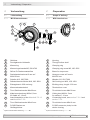
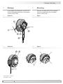
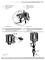
4 Vorbereitung
4.1 Lieferumfang
4.1.1 Mit Klemmenkasten
4 Preparation
4.1 Scope of delivery
4.1.1 With terminal box
1
Gehäuse
2
Durchgehende Hohlwelle
3
Klemmring
4
Klemmringschraube M5, ISO 4762
5
Stütze für Drehmomentstütze
6
Sechskantschraube ø12 mm auf
M10x35 mm
7
Scheibe A13, ISO 7090
8
Selbstsichernde Mutter M10, ISO 10511
9
Erdungsband ~230 mm lang
10
Klemmenkastendeckel
11
Torx-/Schlitzschraube M4x32 mm
12
Kabelverschraubung M20x1,5 mm
für Kabel ø5...13 mm
13
Anschlussplatine, siehe Abschnitt 7.3.1.3
und Abschnitt 7.3.2.
14
Torx-/Schlitzschraube M3x10 mm
15
D-SUB Stecker am
Gerätegehäuse
1)
Option M: Redundante Abtastung HOG 22 M
1
Housing
2
Through hollow shaft
3
Clamping ring
4
Clamping ring screw M5, ISO 4762
5
Brace for torque arm
6
Hexagon screw ø12 mm to
M10x35 mm
7
Washer A13, ISO 7090
8
Self-locking nut M10, ISO 10511
9
Earthing strap, length ~230 mm
10
Terminal box cover
11
Torx/slotted screw M4x32 mm
12
Cable gland M20x1.5 mm
for cable ø5...13 mm
13
Connecting board, see section 7.3.1.3 and
section 7.3.2.
14
Torx/slotted screw M3x10 mm
15
D-SUB connector (male) on the
device housing
1)
Option M: Redundant sensing HOG 22 M

MB049 - 11114026
Baumer_HOG22_II_DE-EN (20A1) 8
Vorbereitung / Preparation 4
116 18
9
16
17
18
8
7
6
5
2
4
3
-
1)1)
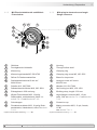
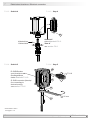
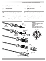
4.1.2 Mit Einschubelektronik und Winkel-
Flanschdose
4.1.2 With plug-in electronics and angle
ange connector
1
Gehäuse
2
Durchgehende Hohlwelle
3
Klemmring
4
Klemmringschraube M5, ISO 4762
5
Stütze für Drehmomentstütze
6
Sechskantschraube ø12 mm auf
M10x35 mm
7
Scheibe A13, ISO 7090
8
Selbstsichernde Mutter M10, ISO 10511
9
Erdungsband ~230 mm lang
16
Winkel-Flanschdose M23, 12-polig,
Stiftkontakte, rechtsdrehend, siehe Ab-
schnitt 7.4.1.3 und Abschnitt 7.4.2.
17
Schutzkappe
18
Rundsteckverbinder M23, 12-polig, Buch-
senkontakte, linksdrehend, siehe Abschnitt
7.4.1.1.
1)
Option M: Redundante Abtastung HOG 22 M
1
Housing
2
Through hollow shaft
3
Clamping ring
4
Clamping ring screw M5, ISO 4762
5
Brace for torque arm
6
Hexagon screw ø12 mm to
M10x35 mm
7
Washer A13, ISO 7090
8
Self-locking nut M10, ISO 10511
9
Earthing strap, length ~230 mm
16
Angle ange connector M23, 12-pin,
male, CW, see section 7.4.1.3 and section
7.4.2.
17
Protection cap
18
Mating connector M23, 12-pin, female,
CCW,
see section 7.4.1.1.
1)
Option M: Redundant sensing HOG 22 M

4 Vorbereitung / Preparation
9 Baumer_HOG22_II_DE-EN (20A1)
MB049 - 11114026
21
21a
21d
21e
21b 21c
19
20
3x
3x
L
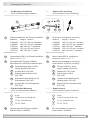
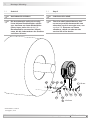
4.2 Zur Montage erforderlich
(nicht im Lieferumfang enthalten)
4.2 Required for mounting
(not included in scope of delivery)
19
Drehmomentstütze, als Zubehör erhältlich:
Bestellnr. Länge L, Version
11054922 155 (-10/+15) mm, Standard
11054921 190 (-10/+15) mm, Standard
11072741 480...540 mm
2)
, Standard
11054924 155 (-10/+15) mm, isoliert
11072723 480...540 mm
2)
, isoliert
2)
Kürzbar auf ≥200 mm
20
Sensorkabel HEK 8, als Zubehör erhältlich,
siehe Abschnitt 7.5.
21
Montageset als Zubehör erhältlich:
Bestellnummer 11069336, bestehend aus ...
21a
Gewindestange M12 (1.4104),
Länge variabel (≤250 mm)
21b
Scheibe B12, ISO 7090
21c
Selbstsichernde Mutter M12,
ISO 10511
21d
Zylinderschraube M6x8 mm für
Erdungsband, ISO 1207
21e
Scheibe B6,4 für Erdungsband,
ISO 7090
4.3 Erforderliches Werkzeug
(nicht im Lieferumfang enthalten)
4 mm
1,6x8,0 mm und 0,8x4 mm
17, 18, 19 und 22 mm
TX 10, TX 20
22
Werkzeugset als Zubehör erhältlich:
Bestellnummer 11068265
19
Torque arm, available as accessory:
Order no. Length L, version
11054922 155 (-10/+15) mm, standard
11054921 190 (-10/+15) mm, standard
11072741 480...540 mm
2)
, standard
11054924 155 (-10/+15) mm, insulated
11072723 480...540 mm
2)
, insulated
2)
Can be shortened to ≥200 mm
20
Sensor cable HEK 8, available as
accessory, see section 7.5.
21
Mounting kit available as accessory:
Order number 11069336, including ...
21a
Thread rod M12 (1.4104),
length variable (≤250 mm)
21b
Washer B12, ISO 7090
21c
Self-locking nut M12,
ISO 10511
21d
Cylinder screw M6x8 mm for
earthing strap, ISO 1207
21e
Washer B6.4 for earthing strap,
ISO 7090
4.3 Required tools
(not included in scope of delivery)
4 mm
1.6x8.0 mm and 0.8x4 mm
17, 18, 19 and 22 mm
TX 10, TX 20
22
Tool kit available as accessory:
Order number 11068265

MB049 - 11114026
Baumer_HOG22_II_DE-EN (20A1) 10
Montage / Mounting 5
5 mm
17 mm
19 mm
6
75
*
**
8
*
19
*
4 3
* *
* Siehe Seite 7, 8 oder 9
See page 7, 8 or 9
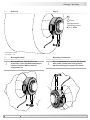
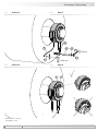
5 Montage
In den Bildern am Beispiel vom HOG 22.
Gleiche Montageschritte bei redundanter
Version HOG 22 M.
5.1 Schritt 1
5 Mounting
Pictures showing HOG 22 as example.
Same mounting steps for redundant
version HOG 22 M.
5.1 Step 1
5.2 Schritt 2 5.2 Step 2

5 Montage / Mounting
11 Baumer_HOG22_II_DE-EN (20A1)
MB049 - 11114026
21c21b21b21c
21b 21c 21a
9
21d21e
****
* * * *
**
18 mm
1.6x8 mm
19
*
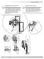
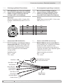
5.3 Schritt 3
5.3 Step 3
Die Antriebswelle sollte einen mög-
lichst kleinen Rundlauffehler aufwei-
sen, da dieser zu einem Winkelfehler
führen kann, siehe Abschnitt 5.5.
Rundlauffehler verursachen Vibrati-
onen, die die Lebensdauer des Gerätes
verkürzen können.
Antriebswelle einfetten. Lubricate drive shaft.
The drive shaft should have as less
runout as possible because this can
otherwise result in an angle error, see
section 5.5. Runouts can cause
vibrations, which can shorten the
service life of the device.
* Siehe Seite 7, 8 oder 9
See page 7, 8 or 9

MB049 - 11114026
Baumer_HOG22_II_DE-EN (20A1) 12
Montage / Mounting 5
15°
15°
9°
9°
9°
9°
L1
L2 (≥L1)
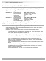
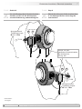
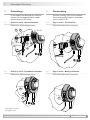
5.4 Montage der Drehmomentstütze
Die Montage der Drehmomentstütze
sollte spielfrei erfolgen. Ein Spiel von
beispielsweise ±0,03 mm entspricht
einem Rundlauffehler des Gerätes von
0,06 mm, was zu einem großen
Winkelfehler führen kann, siehe
Abschnitt 5.5.
5.4 Mounting the torque arm
The torque arm should be mounted
free from clearance. A play of just
±0.03 mm, results in a runout of the
device of 0.06 mm. That may lead to a
large angle error, see section 5.5.

5 Montage / Mounting
13 Baumer_HOG22_II_DE-EN (20A1)
MB049 - 11114026
5.5 Hinweis zur Vermeidung von
Messfehlern
Für einen einwandfreien Betrieb des
Gerätes ist eine korrekte Montage, ins-
besondere auch der Drehmomentstütze,
notwendig.
Der Rundlauffehler der Antriebswelle
sollte möglichst nicht mehr als 0,2 mm
(0,03 mm empfohlen) betragen, da hier-
durch Winkelfehler verursacht werden.
Solche Winkelfehler können durch einen
größeren Abstand L1 reduziert werden
3)
.
Dabei ist zu beachten, dass die Länge L2
der Drehmomentstütze, siehe Abschnitt
5.4, mindestens gleich L1 sein sollte
4)
.
Der Winkelfehler kann wie folgt berechnet
werden:
Δρ
mech
= ± 90°/π · R/L1
mit R: Rundlauffehler in mm
L1: Abstand der Drehmoment-
stütze zum Mittelpunkt
des Gerätes in mm
Berechnungsbeispiel:
Für R = 0,06 mm und L1 = 130 mm ergibt
sich ein Winkelfehler Δρ
mech
von ± 0.013°.
3)
Auf Anfrage sind hierzu verschiedene Stützen für die
Drehmomentstütze erhältlich.
4)
Wenn L2 < L1 muss mit der Länge L2 gerechnet werden.
i
Weitere Informationen erhalten Sie
unter der Telefon-Hotline
+49 (0)30 69003-111
5.5 How to prevent measurement
errors
To ensure that the device operates cor-
rectly, it is necessary to mount it accurate-
ly, which includes correct mounting of the
torque arm.
The radial runout of the drive shaft should
not exceed 0.2 mm (0.03 mm recom-
mended), if at all possible, to prevent an
angle error.
An angle error may be reduced by increa-
sing the length of L1
3)
. Make sure that the
length L2 of the torque arm, see section
5.4, is at least equal to L1
4)
.
The angle error can be calculated as
follows:
Δρ
mech
= ± 90°/π · R/L1
with R: Radial runout in mm
L1: Distance of the torque arm
to the center point of the
device in mm
Example of calculation:
For R = 0.06 mm and L1 = 130 mm the re-
sulting angle error Δρ
mech
equals ± 0.013°.
3)
For this different braces for the torque arm are
available on request.
4)
If L2 < L1, L2 must be used in the calculation formula.
i
For more information,
call the telephone hotline at
+49 (0)30 69003-111

MB049 - 11114026
Baumer_HOG22_II_DE-EN (20A1) 14
Montage / Mounting 5
Anzugsmoment:
Tightening torque:
M
t
= 3...4 Nm
5 mm
4
*
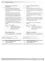
5.6 Schritt 5 5.6 Step 5
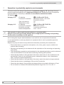
5.7 Montagehinweis 5.7 Mounting instruction
i
Wir empfehlen, das Gerät so zu
montieren, dass der Kabelanschluss
keinem direkten Wassereintritt
ausgesetzt ist.
i
It is recommended to mount the device
with cable connection facing down-
ward and being not exposed to water.
* Siehe Seite 7 oder 8
See page 7 or 8

6 Abmessungen / Dimensions
15 Baumer_HOG22_II_DE-EN (20A1)
MB049 - 11114026
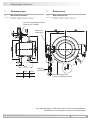
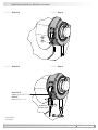
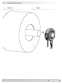
Option M:
redundant
Um 90° versetzt gezeichnet
Drawing 90° rotated
Zubehör
Accessory
IP54 IP56
L1 23 24
L2 112.5 114.5
6 Abmessungen
6.1 Mit Klemmenkasten
(74181, 74182, 74190, 74193)
6 Dimensions
6.1 With terminal box
(74181, 74182, 74190, 74193)
Drehrichtung positiv
Positive rotating direction
Alle Abmessungen in Millimeter (wenn nicht anders angegeben)
All dimensions in millimeters (unless otherwise stated)

MB049 - 11114026
Baumer_HOG22_II_DE-EN (20A1) 16
Abmessungen / Dimensions 6
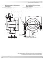
Option M:
redundant
Um 90° versetzt gezeichnet
Drawing 90° rotated
Zubehör
Accessory
IP54 IP56
L1 23 24
L2 112.5 114.5
6.2 Mit Einschubelektronik und Winkel-
Flanschdose
(74183, 74188)
6.2 With plug-in electronics and angle
ange connector
(74183, 74188)
Drehrichtung positiv
Positive rotating direction
Alle Abmessungen in Millimeter (wenn nicht anders angegeben)
All dimensions in millimeters (unless otherwise stated)

7 Elektrischer Anschluss / Electrical connection
17 Baumer_HOG22_II_DE-EN (20A1)
MB049 - 11114026
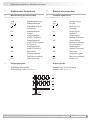
7 Elektrischer Anschluss
7.1 Beschreibung der Anschlüsse
+UB Betriebsspannung
0V (
) Masseanschluss
Erdungsanschluss
(Gehäuse)
K1 Ausgangssignal
Kanal 1
K1
Ausgangssignal
Kanal 1 invertiert
K2 Ausgangssignal
Kanal 2 (90° versetzt
zu Kanal 1)
K2
Ausgangssignal
Kanal 2 invertiert
K0 Nullimpuls
(Referenzsignal)
K0
Nullimpuls invertiert
dnu Nicht benutzen
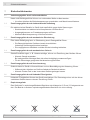
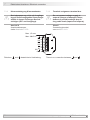
7.2 Ausgangssignale
Signalfolge bei positiver
Drehrichtung, siehe Abschnitt 6.
7 Electrical connection
7.1 Terminal signicance
+UB Voltage supply
0V (
) Ground
Earth ground
(housing)
K1 Output signal
channel 1
K1
Output signal
channel 1 inverted
K2 Output signal
channel 2 (offset by
90° to channel 1)
K2
Output signal
channel 2 inverted
K0 Zero pulse
(reference signal)
K0
Zero pulse inverted
dnu Do not use
7.2 Output signals
Sequence for positive rotating
direction, see section 6.
K1
K1
K2
K2
K0
K0
90°
Seite wird geladen ...
Seite wird geladen ...
Seite wird geladen ...
Seite wird geladen ...
Seite wird geladen ...
Seite wird geladen ...
Seite wird geladen ...
Seite wird geladen ...
Seite wird geladen ...
Seite wird geladen ...
Seite wird geladen ...
Seite wird geladen ...
Seite wird geladen ...
Seite wird geladen ...
Seite wird geladen ...
Seite wird geladen ...
-
 1
1
-
 2
2
-
 3
3
-
 4
4
-
 5
5
-
 6
6
-
 7
7
-
 8
8
-
 9
9
-
 10
10
-
 11
11
-
 12
12
-
 13
13
-
 14
14
-
 15
15
-
 16
16
-
 17
17
-
 18
18
-
 19
19
-
 20
20
-
 21
21
-
 22
22
-
 23
23
-
 24
24
-
 25
25
-
 26
26
-
 27
27
-
 28
28
-
 29
29
-
 30
30
-
 31
31
-
 32
32
-
 33
33
-
 34
34
-
 35
35
-
 36
36


Baumer HOG 22 Installation and Operating Instructions
- Typ
- Installation and Operating Instructions
in anderen Sprachen
- English: Baumer HOG 22
Verwandte Artikel
-
Baumer AG 14 Installation and Operating Instructions
-
-
Baumer HOG 22 Datenblatt
-
-
-
-
-
-
-