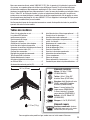
E-flite UMX MiG 15 DF Benutzerhandbuch
- Kategorie
- Ferngesteuertes Spielzeug
- Typ
- Benutzerhandbuch

Instruction Manual
Bedienungsanleitung
Manuel d’utilisation
Manuale di Istruzioni
UMX
™
MiG 15 DF

2
EN
Age Recommendation: Not for children under 14 years. This is not a toy.
WARNING: Read the ENTIRE instruction manual to become familiar with the features of the
product before operating. Failure to operate the product correctly can result in damage to the product,
personal property and cause serious injury.
This is a sophisticated hobby product. It must be operated with caution and common sense and
requires some basic mechanical ability. Failure to operate this product in a safe and responsible
manner could result in injury or damage to the product or other property. This product is not intended
for use by children without direct adult supervision. Do not attempt disassembly, use with incompatible
components or augment product in any way without the approval of Horizon Hobby, Inc. This manual
contains instructions for safety, operation and maintenance. It is essential to read and follow all the
instructions and warnings in the manual, prior to assembly, setup or use, in order to operate correctly
and avoid damage or serious injury.
NOTICE
All instructions, warranties and other collateral documents are subject to change at the sole discretion
of Horizon Hobby, Inc. For up-to-date product literature, visit www.horizonhobby.com and click on the
support tab for this product.
Meaning of Special Language:
The following terms are used throughout the product literature to indicate various levels of potential
harm when operating this product:
NOTICE: Procedures, which if not properly followed, create a possibility of physical property damage AND
little or no possibility of injury.
CAUTION: Procedures, which if not properly followed, create the probability of physical property damage
AND a possibility of serious injury.
WARNING: Procedures, which if not properly followed, create the probability of property damage,
collateral damage, and serious injury OR create a high probability of superfi cial injury.

3
EN
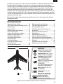
Thank you for purchasing the E-fl ite
®
UMX
™
MiG 15 DF. A breakthrough in ultra micro electric ducted fan
technology, your new E-fl ite jet is an accurate replica of the original Mikoyan-Gurevich design. Using
modern manufacturing techniques and sophisticated components, E-fl ite is able to produce your new scale
RC swept-wing jet fi ghter fully assembled out of the box with proportional 4-channel control. At its heart is
inlet and exhaust ducting specially engineered to harness the full potential of the incredible 28mm Delta-V
®
180m EDF system without the need of any unsightly cheater holes on the bottom of the model. And so that
you also enjoy the most realistic jet fl ight experience possible, your UMX MiG 15 DF is also equipped with
the amazing AS3X
®
System that’s been specially tuned to provide smooth, natural feeling control over a
wide speed range, plus rock solid fl ight performance, even in moderate wind.
Please be sure to read through this manual carefully so that you are equipped to successfully enjoy all the
benefi ts this outstanding ultra micro model has to offer.
To register your product online, go to www.e-fl iterc.com
Table of Contents
Prefl ight Checklist .................................................4
AS3X
®
System Delivers
Breakthrough Performance ..................................4
Charging Warnings................................................4
Charging the Battery .............................................5
Transmitter and Receiver Binding .........................6
Installing the Flight Battery ..................................6
Arming the ESC ....................................................7
Low Voltage Cutoff (LVC) .......................................7
Control Centering ..................................................8
Settings for Control Horns .....................................8
Control Direction Test ............................................8
Dual Rates and Expos ...........................................9
DX4e and DX5e Expo Activation and Deactivation .9
Adjusting Center of Gravity (CG) ..........................10
Installing the Optional Landing Gear ....................10
Flying Tips and Repairs .......................................11
Installing Optional Cannons .................................12
Additional Safety Precautions and Warnings ........12
Service of Power Components ............................13
Troubleshooting Guide ........................................14
Troubleshooting Guide (Continued) ......................15
Limited Warranty ................................................16
Warranty and Service Information .......................17
Compliance Information for the European Union ..17
Replacement Parts ..............................................66
Optional Parts and Accessories ...........................67
Parts Contact Information ...................................67
Motor: BL180m Ducted Fan Motor,
11750Kv (EFLM30180mDFA)
Ducted Fan unit: Delta-V 180m
28mm EDF Unit (EFLDF180m)
Receiver: Spektrum DSMX
®
6Ch AS3X
®
Receiver w/BL ESC
(SPMAS6410NBL)
Servo: (2) 2.3-Gram Performance
Linear Long Throw Servo
(SPMSA2030L)
(2) 2.3-Gram Linear Long Throw
Offset Servos (SPMSA2030LO)
Battery: 200mAh 2S 25C Li-Po
(EFLB2002S25)
Battery Charger: 2S 7.4V Li-Po
(EFLUC1007)
Recommended Transmitter:
Spektrum
™
DSM2
®
/DSMX
®
with
dual-rates (DX4e and up)
Needed to Complete
Installed
15.9 in (402mm)
16.2 in (412mm)
2.75 oz (77.5 g)

4
EN
Prefl ight Checklist
1. Charge fl ight battery.
2. Install fl ight battery in aircraft
(once it has been fully charged).
3. Bind aircraft to transmitter.
4. Make sure linkages move freely.
5. Perform Control Direction Test with
transmitter.
6. Set dual rates and exponential.
7. Adjust center of gravity.
8. Perform a radio system Range Check.
9. Find a safe and open area.
10. Plan fl ight for fl ying fi eld conditions.
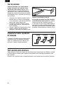
AS3X
®
System Delivers
Breakthrough Performance
Horizon Hobby has always made RC sport, scale
and unique aircraft with the kind of performance
experts appreciate. Now the exclusive Artificial
Stability – 3 aXis (AS3X) system helps take
performance expectations in ultra micro aircraft a
quantum leap higher.
Based on the successful use of MEMS sensor
technology within the AS3X Stabilization System
essential to Blade
®
ultra micro flybarless
helicopters, the specifically tuned AS3X System
for airplanes helps invisibly correct for turbulence,
torque and tip stalls when encountered.
Furthermore, the outstanding control agility delivers
an ultra smooth, locked-in feel that obeys your
every command with performance that’s natural
feeling. It’s so gratifying, in fact, that it’s as though
you’re the RC pilot of an expertly tuned, giant-scale
model.
AS3X will change the way you’ll want to fly now and
in the future. To see what we mean, go to
www.E-fliteRC.com/AS3X.
Charging Warnings
The included battery charger (EFLUC1007) has been
designed to safely charge the Li-Po battery.
CAUTION: All instructions and warnings must
be followed exactly. Mishandling of Li-Po batteries
can result in a fi re, personal injury, and/or property
damage.
• By handling, charging or using the included Li-Po
battery, you assume all risks associated with
lithium batteries.
• If at any time the battery begins to balloon or
swell, discontinue use immediately. If charging
or discharging, discontinue and disconnect.
Continuing to use, charge or discharge a battery
that is ballooning or swelling can result in fi re.
• Always store the battery at room temperature in a
dry area for best results.
• Always transport or temporarily store the battery
in a temperature range of 40–120º F (4–49º C).
Do not store battery or aircraft in a car or direct
sunlight. If stored in a hot car, the battery can be
damaged or even catch fi re.
• Always charge batteries away from fl ammable
materials.
• Always inspect the battery before charging and
never charge damaged batteries.
• Always disconnect the battery after charging, and
let the charger cool between charges.
• Always constantly monitor the temperature of the
battery pack while charging.
• ONLY USE A CHARGER SPECIFICALLY DESIGNED
TO CHARGE LI-PO BATTERIES. Failure to charge
the battery with a compatible charger may cause
fi re resulting in personal injury and/or
property damage
• Never discharge Li-Po cells to below 3V
under load.
• Never cover warning labels with hook and
loop strips.
• Never leave charging batteries unattended.
• Never charge batteries outside
recommended levels.
• Never attempt to dismantle or alter the charger.
• Never allow minors to charge battery packs.
• Never charge batteries in extremely hot or cold
places (recommended between 40–120° F or
4–49° C) or place in direct sunlight.

5
EN
Your aircraft comes with a 2-Cell 7.4V 200mAh 25C
Li-Po battery and a Celectra
™
2S 7.4V DC Li-Po
Charger that requires a 12V (11V–14V) DC power
source.
Refer to the battery warnings. It is recommended
to charge the battery pack while you are inspecting
the aircraft. The fl ight battery will be required to
confi rm proper aircraft operation in future steps.
Please visit www.horizonhobby.com for optional
battery adapters.
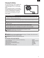
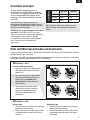
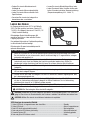
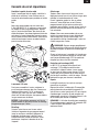
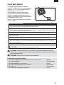
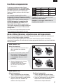
Charging the Battery
The Battery Charging Process
1. Charge only batteries that are cool to the touch and are not damaged. Inspect the battery to make sure it is not
damaged e.g., swollen, bent, broken or punctured.
2. The connector of the battery is specifi cally designed to allow it to fi t into the charge port one way to prevent
reverse polarity connection. However, check for proper alignment and polarity before proceeding to the next step.
3. Gently press the battery connector into the charge port located on the front of the charger.
4. When you make the connection successfully, the green LED blinking on the charger slows, indicating
proper connection.
5. Press the button on the charger. The red LED will illuminate, indicating charging has begun.
6. Charging a fully discharged (not over-discharged) 200mAh battery takes approximately 50–60 minutes at the
charger’s 300mA charge rate. The included battery can be charged at a rate of up to 3C (600mA).
7. When the battery is fully charged, the green LED will turn solid.
8. Always unplug the battery from the charger immediately upon completion of charging.
CAUTION: Overcharging a battery can cause a fi re.
2S 7.4V 200mAh 25C
Lithium Polymer Battery
CAUTION: Only use a charger specifi cally designed to charge a Li-Po battery. Failure to do so could
result in fi re causing injury or property damage.
CAUTION: Never exceed the recommended charge rate.
LED Functions under normal operation
1. Green LED blinking with power connected but without battery ................................... Standby
2. Green LED blinking .................................................................................................... Battery is connected
3. Blinking Red LED at varying speeds ........................................................................... Charging
4. Red and Green LED blinking simultaneously ............................................................... Balancing
5. Solid Green LED ....................................................................................................... Full Charge
6. Red and Green LED fl ashing rapidly ........................................................................... Error

6
EN
Transmitter and Receiver Binding
Binding is the process of programming the receiver of the control unit to recognize the GUID (Globally
Unique Identifi er) code of a single specifi c transmitter. You need to ‘bind’ your chosen Spektrum
TM
DSM2
®
/
DSMX
®
technology equipped aircraft transmitter to the receiver for proper operation.
Any JR
®
or Spektrum DSM2/DSMX transmitter can bind to the AS3X DSM
®
receiver. For best fl ight
performance of the UMX
™
MiG 15 DF, it is recommended that you use a transmitter with exponential and dual
rates. Please visit www.bindnfl y.com for a complete list of compatible transmitters.
NOTICE: When using a Futaba
®
transmitter with a Spektrum DSM module, reversing the throttle channel
is required.
Binding Procedure
1. Refer to your transmitter’s unique instructions for binding to a receiver.
2. Make sure the fl ight battery is disconnected from the aircraft.
3. Power off the transmitter.
4. Connect the fl ight battery in the aircraft. The receiver LED will begin to fl ash rapidly (typically after 5 seconds).
5. Make sure the transmitter controls are at neutral and the throttle and throttle trim are in the low position.
6. Put your transmitter into bind mode. Refer to your transmitter’s manual for binding button or
switch instructions.
7. After 5 to 10 seconds, the receiver status LED will become solid, indicating that the receiver is bound to the
transmitter. If the LED does not turn solid, refer to the Troubleshooting Guide at the back of the manual.
For subsequent fl ights, power on the transmitter for 5 seconds before connecting the fl ight battery.
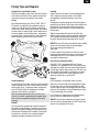
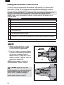
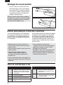
Installing the Flight Battery
1. Attach the flight battery to the hook and loop
strip (A) on the battery tray. See the Adjusting
the Center of Gravity instructions for the
battery’s position.
2. Place the aircraft on the ground out of the wind
and connect a fully charged flight battery.
Ensure the aircraft is immobile for 5
seconds so the AS3X system can initialize
correctly. See the Arming the ESC instructions
for correct connection of the battery to the ESC.
NOTICE: Always ensure that the battery is secured
in the aircraft using hook and loop tape.
CAUTION: Always disconnect the Li-Po
battery from the aircraft receiver when not fl ying to
avoid over-discharging the battery. Batteries
discharged to a voltage lower than the lowest
approved voltage may become damaged, resulting
in loss of performance and potential fi re when
batteries are charged.
A

7
EN
1 2
3
If you accidentally connect the battery while the throttle is fully raised, the ESC will enter programming
mode. Disconnect the battery immediately.
The AS3X system will not activate until the throttle stick or trim is increased for the fi rst time. Once the AS3X
is active, the control surfaces may move rapidly on the aircraft. This is normal.
AS3X will remain active until the battery is disconnected.
NOTICE: Always keep material or debris away from the intake. When armed, the rotor will turn in response
to the throttle movement and could ingest in any loose objects.
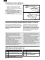
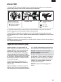
Arming the ESC
Arming the ESC also occurs after binding as previously described, but subsequent connection of a fl ight
battery requires the steps below.
Lower throttle and throttle
trim to lowest settings.
Power on the Transmitter
then wait 5 seconds
Install fl ight battery and
connect it to the ESC.
Keep plane immobile
and away from wind for
5 seconds.
Series of tones
Continuous LED
Low Voltage Cutoff (LVC)
When a Li-Po battery is discharged below 3V per
cell, it will not hold a charge. The aircraft’s ESC
protects the fl ight battery from over-discharge using
Low Voltage Cutoff (LVC). Before the battery charge
decreases too much, LVC removes power supplied
to the motor. Power to the motor quickly decreases
and increases, showing that some battery power is
reserved for fl ight control and safe landing.
When the motor power pulses, land the aircraft
immediately and recharge the fl ight battery.
Disconnect and remove the Li-Po battery from the
aircraft after use to prevent trickle discharge. During
storage, make sure the battery charge does not fall
below 3V per cell.
Tip: Due to the quiet nature of the aircraft, you may
not hear the pulsing of the motor.
For your fi rst fl ights, set your transmitter timer or a
stopwatch to 3 minutes. Adjust your timer for longer
or shorter fl ights once you have fl own the aircraft.
Flights of 4 minutes or more are achievable if using
proper throttle management.
NOTICE: Repeated fl ying to LVC will damage
the battery.

8
EN
You should bind your aircraft and transmitter before doing these tests. Move the controls on the transmitter
to make sure aircraft control surfaces move correctly and in the proper direction.
Make sure tail linkages move freely and that paint or decals are not adhered to them.
Control Direction Test
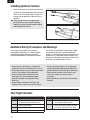
Settings for Control Horns
The following illustration shows the factory settings
for linkages on the control horns. After fl ying,
carefully adjust the linkage positions for the desired
control response.
Aileron Elevator Rudder
Before the fi rst fl ights, or in the event of an
accident, make sure the fl ight control surfaces
are centered. Adjust the linkages mechanically if
the control surfaces are not centered. Use of the
transmitter sub-trims may not correctly center the
aircraft control surfaces due to the mechanical
limits of linear servos.
1. Make sure the control surfaces are neutral
when the transmitter controls and trims are
centered. The transmitter sub-trim must
always be set to zero.
2. When needed, use a pair of pliers to carefully
bend the metal linkage (see illustration).
3. Make the U-shape narrower to make the
connector shorter. Make the U-shape wider
to make the linkage longer.
Centering Controls After First Flights
For best performance with AS3X, it is important
that excessive trim is not used. If the model re-
quires excessive transmitter trim (4 or more clicks
of trim per channel), return the transmitter trim
to zero and adjust the linkages mechanically so
that the control surfaces are in the fl ight trimmed
position.
Control Centering

9
EN
Dual Rates and Expos
To obtain the best fl ight performance, we
recommend using a DSM2/DSMX radio capable
of Dual Rates. The suggested settings shown here
are the recommended starting settings. Adjust
according to the individual preferences after the
initial fl ight.
If using the DX4e or DX5e transmitters, we
recommend activating Expo for smoother control.
For activation and deactivation of Expo in the DX4e
and DX5e, see the next section.
NOTICE: Do not set your transmitter travel adjust
over 100%. If the TRAVEL ADJUST is set over
100%, it will not result in more control movement, it
will overdrive the servo and cause damage.
It is normal for linear servos to make signifi cant
noise. The noise is not an indication of a
faulty servo.
Tip: For the fi rst fl ight, fl y the model in low rate.
Tip: For landing, we recommend using high rate
elevator.
Dual Rates
High Rate Low Rate
Aileron 100% 70%
Elevator 100% 70%
Rudder 100% 70%
DX4e (Modes 1 and 2)
Activate and Deactivate Expo
1. Put the ACT switch in the down position
(ON) and the Rate switch in the down
position (LO).
2. Push and hold the trainer (bind) button
and move and hold the two sticks (as
shown here) for activation (A) or
deactivation (B), while powering on
the transmitter.
3. Release the trainer switch and the
control sticks only after a series of
tones sound (ascending tones for
activation, descending tones for
deactivation).
DX4e and DX5e Expo Activation and Deactivation
If you plan to fl y your aircraft with a DX4e or DX5e, disconnect the battery from the aircraft before activating
the Expo feature in your transmitter.
Once Expo is activated, it will remain activated for subsequent power cycles of the transmitter. Once Expo is
deactivated, it will remain deactivated until it is activated again.
A
B
DX5e (Modes 1 and 2)
Activate Expo
1. Hold the aileron trim switch to the right when
powering on the transmitter.
2. Release the aileron trim switch after a series
of ascending tones to confirm that Expo is
activated.
Deactivate Expo
1. Hold the aileron trim switch to the left when
powering on the transmitter.
2. Release the aileron trim switch after a series
of descending tones to confirm that Expo is
deactivated.

10
EN
Adjusting Center of Gravity (CG)
The CG location is 58mm back from leading edge
of the wing at the root. This CG location has been
determined with the included 2S 200mAh 7.4V
Li-Po battery.
The battery tray is oversized to allow for Center of
Gravity adjustment. Start by placing the battery near
the rear edge of the battery tray with the connector
plug facing the front of the aircraft. Adjust as
needed by sliding the battery forward or back.
58mm
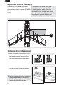
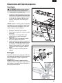
1. Gently slide the left and right main landing gear
into the plastic mounting clips on the bottom
of the wings as shown. The main gear are
configured for a left and right side.
2. Carefully slide the nose gear into the plastic
nose gear mount on the bottom of the
fuselage.
Tip: The nose gear strut wire can be twisted a
small amount to adjust the ground tracking.
Always remove the nose gear from the aircraft
before performing this adjustment.
Installing the Optional Landing Gear

11
EN
Range Check your Radio System
After fi nal assembly, range check the radio system
with the aircraft. Refer to your specifi c transmitter
instruction manual for range test information.
Flying
We recommend fl ying your E-fl ite
®
UMX
™
MiG 15
DF
outside in no greater than moderate winds or
inside in a large gymnasium. Always avoid fl ying
near houses, trees, wires and buildings. You should
also be careful to avoid fl ying in areas where there
are many people, such as busy parks, schoolyards
or soccer fi elds. Consult local laws and ordinances
before choosing a location to fl y your aircraft.
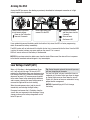
Hand Launching
To hand launch this model, hold the aircraft fuselage
under the wings. Give a fi rm throw directly into the
wind slightly up (5–10 degrees above the horizon)
with full throttle. After the model gains altitude,
decrease the throttle as you desire.
Tip: The electric ducted fan (EDF) acts like a jet
aircraft, so control is generated by airspeed rather
than air from a propeller moving over the control
surfaces.
Takeoff
Taxi the aircraft in position for takeoff (facing into
the wind if fl ying outdoors). Gradually increase the
throttle to full power, holding a small amount of up
elevator and steering with the rudder. Climb gently
to check trim. Once the trim is adjusted, begin
exploring the fl ight envelope of the aircraft.
Landing
Always land into the wind. Fly the landing pattern
with a slightly nose high attitude. Use throttle
management to control the decent rate of the
aircraft.
During fl are, keep the wings level and the airplane
pointed into the wind. Gently lower the throttle while
pulling back on the elevator to bring the aircraft
down on the main wheels or to belly land without
landing gear.
Tip: We recommend that you do not install the
optional nose cannons for belly landings. Installation
of this option could prevent smooth belly landings
on grass and could cause damage to the aircraft.
NOTICE: Always fully lower the throttle when landing
the aircraft to prevent intake of foreign objects,
which can damage the ducted fan
and motor.
Failure to lower the throttle stick and trim to the
lowest possible positions during a crash could result
in damage to the ESC in the receiver unit, which
may require replacement.
Over Current Protection (OCP)
The MiG 15 DF is equipped with Over Current
Protection. OCP protects the ESC from overheating
and stops the motor when the transmitter throttle is
set too high and the rotor cannot turn. OCP will only
activate when the throttle is positioned just above
1/2 throttle. After the ESC stops the motor, fully
lower the throttle to re-arm the ESC.
Repairs
Crash damage is not covered under warranty.
Repair this aircraft using foam-compatible CA glue
or clear tape. Only use foam-compatible CA glue
as other types of glue can damage the foam. When
parts are not repairable, see the Replacement Parts
List for ordering by item number.
For a listing of all replacement and optional parts,
refer to the list at the back of this manual.
NOTICE: Use of foam-compatible CA accelerant on
your aircraft can damage paint. DO NOT handle the
aircraft until accelerant fully dries.
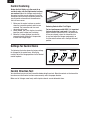
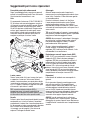
Flying Tips and Repairs
Fly in this area
Stand here
600
feet (182.8 m)
Wind

12
EN
As the user of this product, you are solely
responsible for operating in a manner that does
not endanger yourself and others or result in
damage to the product or the property of others.
This aircraft is controlled by a radio signal subject
to interference from many sources outside your
control. This interference can cause momentary loss
of control, so it is advisable to always keep a safe
distance in all directions around your aircraft as this
space will help avoid collisions or injury.
Additional Safety Precautions and Warnings
Post Flight Checklist
1. Disconnect fl ight battery from ESC
(Required for Safety and battery life).
2. Power off transmitter.
3. Remove fl ight battery from aircraft.
4. Recharge fl ight battery.
5. Store fl ight battery apart from aircraft
and monitor the battery charge.
6. Make note of fl ight conditions and fl ight
plan results, planning for future fl ights.
• Always keep a safe distance in all directions
around your aircraft to avoid collisions or injury.
• Always operate your aircraft in open spaces away
from full-size vehicles, traffi c and people.
• Always carefully follow the directions and
warnings for this and any optional support
equipment (chargers, rechargeable battery
packs, etc.).
• Always keep all chemicals, small parts and
anything electrical out of the reach of children.
• Always avoid water exposure to all equipment
not specifi cally designed and protected for this
purpose. Moisture causes damage to electronics.
• Never place any portion of the aircraft in your
mouth as it could cause serious injury or
even death.
• Never operate your aircraft with low transmitter
batteries.
1. Install the cannons in the nose of your aircraft
as shown. Use the sharp end of the cannons to
make a hole in the foam of each location. The
cannons can be glued in or flown with just a
friction fit.
Tip: These cannon are for scale appearance.
Installing them on your aircraft when belly
landing may hinder safe and smooth landing
and/or damage the aircraft.
Installing Optional Cannons

13
EN
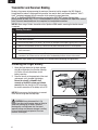
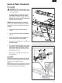
Service of Power Components
Disassembly
CAUTION: DO NOT handle the rotor or motor
while the fl ight battery is connected. Personal
injury could result
.
1. The canopy hatch is secured to the fuselage
using double-sided tape under the outside
edge. Carefully remove the canopy hatch, the
screw (A) and nose gear arm (B); replacing the
double-sided tape as needed.
NOTICE: Removing tape or decals can damage
paint on your aircraft. Avoid pinching or otherwise
damaging any wires when opening or closing the
fuselage.
2. Disconnect the motor connector from the
receiver.
3. Turn over the aircraft so that the landing gear
faces up.
4. Cut the tape and decals on the fuselage and
carefully remove the lower fuselage (C).
5. Remove the 4 screws (D) and fan unit (E) from
the upper fuselage.
6. Put a small flat blade screwdriver in the motor
mount hole (F) and carefully push the rotor (G)
away from the motor shaft. Rotate the rotor
while prying it away from the motor to avoid
bending the motor shaft.
7. Remove the 4 screws (H) and motor (I) from
the motor mount.
Assembly
Assemble in reverse order, connecting the top and
bottom half of the fuselage with clear tape and the
canopy hatch with double stick tape.
NOTICE: Always install the motor mount so that the
rotor faces the front of the fuselage and the hole in
the unit faces the bottom of the fuselage.
Removing tape or decals may remove paint from
the fuselage.
A
B
C
D
E
F
G
H
I

14
EN
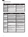
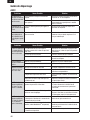
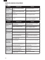
Troubleshooting Guide
Problem Possible Cause Solution
Aircraft will not
respond to throttle
but responds to other
controls
Throttle stick and/or throttle trim too high Reset controls with throttle stick and throttle
trim at lowest setting
Throttle channel is reversed Reverse throttle channel on transmitter
Motor disconnected from receiver Open fuselage and make sure motor is
connected to the receiver
Extra motor noise or
extra vibration
Damaged rotor or motor Replace damaged parts
Rotor out of balance Balance or replace the rotor
Reduced fl ight time
or aircraft underpow-
ered
Flight battery charge is low Completely recharge fl ight battery
Flight battery damaged Replace fl ight battery and follow fl ight battery
instructions
Flight conditions may be too cold Make sure battery is warm before use
Battery capacity too low for fl ight conditions Replace battery or use a larger capacity battery
LED on receiver
fl ashes and aircraft
will not bind to
transmitter (during
binding)
Transmitter too near aircraft during binding
process
Power off transmitter, move transmitter a larger
distance from aircraft, disconnect and recon-
nect fl ight battery to aircraft and follow binding
instructions
Bind switch or button not held long enough
during bind process
Power off transmitter and repeat bind process.
Hold transmitter bind button or switch until
receiver is bound
LED on receiver
fl ashes rapidly and
aircraft will not re-
spond to transmitter
(after binding)
Less than a 5-second wait between fi rst
powering on transmitter and connecting
fl ight battery to aircraft
Leaving transmitter on, disconnect and recon-
nect fl ight battery to aircraft
Aircraft bound to different model memory
(ModelMatch
™
radios only)
Select correct model memory on transmitter
and disconnect and reconnect fl ight battery to
aircraft
Flight battery/transmitter battery charge is
too low
Replace/recharge batteries
Problem Possible Cause Solution
Control surfaces not
at neutral position
when transmitter
controls are at neutral
Control surfaces may not have been
mechanically centered from factory
Center control surfaces mechanically by
adjusting the U-bends on control linkages
Aircraft was moved after the fl ight battery
was connected and before sensors
initialized
Disconnect and reconnect the fl ight battery
while keeping the aircraft still for 5 seconds
Model fl ies incon-
sistently from fl ight
to fl ight
Trims are moved too far from neutral
position
Neutralize trims and mechanically adjust
linkages to center control surfaces
Controls oscillate in
fl ight (model rapidly
jumps or moves)
Rotor is unbalanced, causing excessive
vibration
Remove rotor and motor. Check motor shaft for
straightness and replace rotor if damaged
AS3X

15
EN
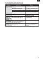
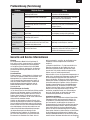
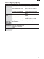
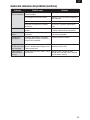
Troubleshooting Guide (Continued)
Problem Possible Cause Solution
Control surface does
not move
Control surface, control horn, linkage or
servo damage
Replace or repair damaged parts and adjust
controls
Wire damaged or connections loose Do a check of wires and connections, connect
or replace as needed
Flight battery charge is low Fully recharge fl ight battery
Control linkage does not move freely Make sure control linkage moves freely
Controls reversed Transmitter settings reversed Adjust controls on transmitter appropriately
Motor loses power Damage to motor or power components Do a check of motor and power components
for damage (replace as needed)
Motor power quickly
decreases and
increases then motor
loses power
Battery power is down to the point of
receiver/ESC Low Voltage Cutoff (LVC)
Recharge fl ight battery or replace battery that
is no longer performing
Motor/ESC is not
armed after landing
Over Current Protection (OCP) stops the
motor when the transmitter throttle is set
high and the rotor cannot turn
Fully lower throttle and throttle trim to arm ESC
Servo locks or freezes
at full travel
Travel adjust value is set above 100%
overdriving the servo
Set Travel adjust to 100% or less and/or set
sub-trims to zero and adjust linkages
mechanically

16
EN
Limited Warranty
What this Warranty Covers
Horizon Hobby, Inc. (“Horizon”) warrants to the original
purchaser that the product purchased (the “Product”) will
be free from defects in materials and workmanship at the
date of purchase.
What is Not Covered
This warranty is not transferable and does not cover (i)
cosmetic damage, (ii) damage due to acts of God, acci-
dent, misuse, abuse, negligence, commercial use, or due
to improper use, installation, operation or maintenance,
(iii) modification of or to any part of the Product, (iv)
attempted service by anyone other than a Horizon Hobby
authorized service center, (v) Product not purchased from
an authorized Horizon dealer, or (vi) Product not compliant
with applicable technical regulations.
OTHER THAN THE EXPRESS WARRANTY ABOVE, HORIZON
MAKES NO OTHER WARRANTY OR REPRESENTATION, AND
HEREBY DISCLAIMS ANY AND ALL IMPLIED WARRANTIES,
INCLUDING, WITHOUT LIMITATION, THE IMPLIED
WARRANTIES OF NON-INFRINGEMENT, MERCHANTABILITY
AND FITNESS FOR A PARTICULAR PURPOSE. THE
PURCHASER ACKNOWLEDGES THAT THEY ALONE HAVE
DETERMINED THAT THE PRODUCT WILL SUITABLY MEET
THE REQUIREMENTS OF THE PURCHASER’S INTENDED USE.
Purchaser’s Remedy
Horizon’s sole obligation and purchaser’s sole and
exclusive remedy shall be that Horizon will, at its option,
either (i) service, or (ii) replace, any Product determined
by Horizon to be defective. Horizon reserves the right
to inspect any and all Product(s) involved in a warranty
claim. Service or replacement decisions are at the sole
discretion of Horizon. Proof of purchase is required for
all warranty claims. SERVICE OR REPLACEMENT AS
PROVIDED UNDER THIS WARRANTY IS THE PURCHASER’S
SOLE AND EXCLUSIVE REMEDY.
Limitation of Liability
HORIZON SHALL NOT BE LIABLE FOR SPECIAL, INDIRECT,
INCIDENTAL OR CONSEQUENTIAL DAMAGES, LOSS OF
PROFITS OR PRODUCTION OR COMMERCIAL LOSS IN ANY
WAY, REGARDLESS OF WHETHER SUCH CLAIM IS BASED
IN CONTRACT, WARRANTY, TORT, NEGLIGENCE, STRICT
LIABILITY OR ANY OTHER THEORY OF LIABILITY, EVEN IF
HORIZON HAS BEEN ADVISED OF THE POSSIBILITY OF
SUCH DAMAGES. Further, in no event shall the liability
of Horizon exceed the individual price of the Product on
which liability is asserted. As Horizon has no control over
use, setup, final assembly, modification or misuse, no
liability shall be assumed nor accepted for any resulting
damage or injury. By the act of use, setup or assembly,
the user accepts all resulting liability. If you as the pur-
chaser or user are not prepared to accept the liability
associated with the use of the Product, purchaser is advi-
sed to return the Product immediately in new and unused
condition to the place of purchase.
Law
These terms are governed by Illinois law (without regard
to conflict of law principals). This warranty gives you
specific legal rights, and you may also have other rights
which vary from state to state. Horizon reserves the right
to change or modify this warranty at any time without
notice.
WARRANTY SERVICES
Questions, Assistance, and Services
Your local hobby store and/or place of purchase cannot
provide warranty support or service. Once assembly,
setup or use of the Product has been started, you must
contact your local distributor or Horizon directly. This will
enable Horizon to better answer your questions and servi-
ce you in the event that you may need any assistance. For
questions or assistance, please visit our website at www.
horizonhobby.com, submit a Product Support Inquiry, or
call 877.504.0233 toll free to speak to a Product Support
representative.
Inspection or Services
If this Product needs to be inspected or serviced and is
compliant in the country you live and use the Product in,
please use the Horizon Online Service Request submissi-
on process found on our website or call Horizon to obtain
a Return Merchandise Authorization (RMA) number. Pack
the Product securely using a shipping carton. Please note
that original boxes may be included, but are not designed
to withstand the rigors of shipping without additional
protection. Ship via a carrier that provides tracking and
insurance for lost or damaged parcels, as Horizon is not
responsible for merchandise until it arrives and is accep-
ted at our facility. An Online Service Request is available
at Horizon Hobby Service Center. If you do not have
internet access, please contact Horizon Product Support
to obtain a RMA number along with instructions for sub-
mitting your product for service. When calling Horizon,
you will be asked to provide your complete name, street
address, email address and phone number where you can
be reached during business hours. When sending product
into Horizon, please include your RMA number, a list of
the included items, and a brief summary of the problem.
A copy of your original sales receipt must be included
for warranty consideration. Be sure your name, address,
and RMA number are clearly written on the outside of the
shipping carton.
NOTICE: Do not ship LiPo batteries to Horizon. If you
have any issue with a LiPo battery, please contact the
appropriate Horizon Product Support office.
Warranty Requirements
For Warranty consideration, you must include your
original sales receipt verifying the proof-of-purcha-
se date. Provided warranty conditions have been met,
your Product will be serviced or replaced free of charge.
Service or replacement decisions are at the sole discreti-
on of Horizon.
Non-Warranty Service
Should your service not be covered by warranty,
service will be completed and payment will be requi-
red without notification or estimate of the expense
unless the expense exceeds 50% of the retail pur-
chase cost. By submitting the item for service you are
agreeing to payment of the service without notification.
Service estimates are available upon request. You must
include this request with your item submitted for service.
Non-warranty service estimates will be billed a minimum
of ½ hour of labor. In addition you will be billed for return
freight. Horizon accepts money orders and cashier’s
checks, as well as Visa, MasterCard, American Express,
and Discover cards. By submitting any item to Horizon
for service, you are agreeing to Horizon’s Terms and
Conditions found on our website Horizon Hobby
Service Center.
NOTICE: Horizon service is limited to Product com-
pliant in the country of use and ownership. If non-
-compliant product is received by Horizon for service,
it will be returned unserviced at the sole expense of
the purchaser.

17
EN
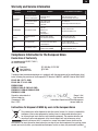
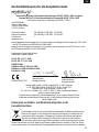
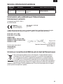
Declaration of Conformity
Compliance Information for the European Union
(in accordance with ISO/IEC 17050-1)
No. HH2012030803
Product(s): EFL UMX Mig 15 EDF BNF
Item Number(s): EFLU1680
Equipment class: 1
The object of declaration described above is in conformity with the requirements of the specifi cations listed
below, following the provisions of the European R&TTE directive 1999/5/EC and EMC Directive 2004/108/EC:
EN 301 489-1 V1.7.1: 2006
EN 301 489-17 V1.3.2: 2008
EN55022: 2006,
EN55024: 1998+A1: 2001+A2: 2003
EN61000-3-2:2006+A1:2009+A2:2009
EN61000-3-3:2008
Signed for and on behalf of:
Horizon Hobby, Inc.
Champaign, IL USA
Mar 8, 2012
Steven A. Hall
Vice President
International Operations and Risk Management
Horizon Hobby, Inc.
Warranty and Service Information
Country of
Purchase
Horizon Hobby Address Phone Number/Email Address
Horizon Service Center
(Electronics and engines)
4105 Fieldstone Rd
Champaign, Illinois
61822 USA
877-504-0233
Online Repair Request visit:
www.horizonhobby.com/service
Horizon Product Support
(All other products)
4105 Fieldstone Rd
Champaign, Illinois
61822 USA
877-504-0233
productsupport@horizonhobby.com
United Kingdom Horizon Hobby Limited
Units 1-4 Ployters Rd
Staple Tye
Harlow, Essex
CM18 7NS
United Kingdom
+44 (0) 1279 641 097
sales@horizonhobby.co.uk
Germany
Horizon Technischer
Service
Christian-Junge-Straße 1
25337 Elmshorn, Germany
+49 (0) 4121 2655 100
service@horizonhobby.de
France Horizon Hobby SAS
14 Rue Gustave Eiffel
Zone d’Activité du Réveil Matin
91230 Montgeron
+33 (0) 1 60 47 44 70
infofrance@horizonhobby.com
China Horizon Hobby – China
Room 506, No. 97 Changshou Rd.
Shanghai, China, 200060
+86 (021) 5180 9868
info@horizonhobby.com.cn
United States
of America
Instructions for disposal of WEEE by users in the European Union
This product must not be disposed of with other waste. Instead, it is the user’s responsibility
to dispose of their waste equipment by handing it over to a designated collections point
for the recycling of waste electrical and electronic equipment. The separate collection and
recycling of your waste equipment at the time of disposal will help to conserve natural
resources and ensure that it is recycled in a manner that protects human health and the
environment. For more information about where you can drop off your waste equipment for recycling, please
contact your local city offi ce, your household waste disposal service or where you purchased the product.

18
DE
Altersempfehlung: Nicht für Kinder unter 14 Jahren. Dies ist kein Spielzeug.
WARNUNG: Lesen Sie die GESAMTE Bedienungsanleitung, um sich vor dem Betrieb mit den
Produktfunktionen vertraut zu machen. Wird das Produkt nicht korrekt betrieben, kann dies zu Schäden
am Produkt oder persönlichem Eigentum führen oder schwere Verletzungen verursachen.
Dies ist ein hochentwickeltes Hobby-Produkt. Es muss mit Vorsicht und gesundem Menschenverstand
betrieben werden und benötigt gewisse mechanische Grundfähigkeiten. Wird dieses Produkt nicht
auf eine sichere und verantwortungsvolle Weise betrieben, kann dies zu Verletzungen oder Schäden
am Produkt oder anderen Sachwerten führen. Dieses Produkt eignet sich nicht für die Verwendung
durch Kinder ohne direkte Überwachung eines Erwachsenen. Versuchen Sie nicht ohne Genehmigung
durch Horizon Hobby, Inc., das Produkt zu zerlegen, es mit inkompatiblen Komponenten zu verwenden
oder auf jegliche Weise zu erweitern. Diese Bedienungsanleitung enthält Anweisungen für Sicherheit,
Betrieb und Wartung. Es ist unbedingt notwendig, vor Zusammenbau, Einrichtung oder Verwendung alle
Anweisungen und Warnhinweise im Handbuch zu lesen und zu befolgen, damit es bestimmungsgemäß
betrieben werden kann und Schäden oder schwere Verletzungen vermieden werden.
HINWEIS
Alle Anweisungen, Garantien und anderen zugehörigen Dokumente können im eigenen Ermessen von
Horizon Hobby, Inc. jederzeit geändert werden. Die aktuelle Produktliteratur fi nden Sie auf
www.horizonhobby.com unter der Registerkarte „Support“ für das betreffende Produkt.
Spezielle Bedeutungen:
Die folgenden Begriffe werden in der gesamten Produktliteratur verwendet, um auf unterschiedlich
hohe Gefahrenrisiken beim Betrieb dieses Produkts hinzuweisen:
HINWEIS: Wenn diese Verfahren nicht korrekt befolgt werden, können sich möglicherweise
Sachschäden UND geringe oder keine Gefahr von Verletzungen ergeben.
ACHTUNG: Wenn diese Verfahren nicht korrekt befolgt werden, ergeben sich wahrscheinlich
Sachschäden UND die Gefahr von schweren Verletzungen.
WARNUNG: Wenn diese Verfahren nicht korrekt befolgt werden, ergeben sich wahrscheinlich
Sachschäden, Kollateralschäden und schwere Verletzungen ODER mit hoher Wahrscheinlichkeit oberfl -
ächliche Verletzungen.

19
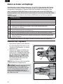
DE
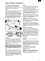
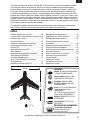
Wir möchten uns recht herzlich für den Kauf der E–fl ite UMX MiG 15 DF bedanken. Mit der revolutionären
Ultra Micro Impeller Technologie ist ihr neuer E–fl ite Jet eine akkurate Replika des Original Mikoyan
Gurevich Design. Unter Verwendung modernster Fertigungsmethoden und hochentwickelter Komponenten
ist es E-fl ite möglich diesen Jäger vollständig in der Box montiert mit proportionaler 4 Kanal Steuerung
anzubieten. Herzstück der Konstruktion ist der unglaublich leistungsstarke 28mm Delta-V Impeller, der
ohne zusätzliche Cheetah Holes seine Performance umsetzen kann. Damit Sie maximale Freude an diesem
Jet Erlebnis haben ist Ihre UMX MiG 15 DF mit dem phantastischen AS3X System ausgestattet, dass Ihnen
über alle Geschwindigkeitsbereiche das beste Fluggefühl bietet und selbst bei moderaten Windstärken eine
unglaublich stabile Basis bietet.
Bitte lesen Sie sich diese Bedienungsanleitung sorgfältig durch, dass Sie alle Vorzüge die dieses Modell
bietet genießen können.
Registrieren Sie Ihr Produkt im Internet unter www.E-fl iterc.com
Inhaltsverzeichnis
Vorbereitung für den Erstfl ug ..............................20
AS3X System liefert bahnbrechende Leistung ....20
Akku Warnungen ................................................20
Laden des Akkus ................................................21
Binden von Sender und Empfänger .....................22
Einsetzen des Flugakkus ....................................22
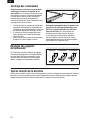
Armieren (Scharfschalten) des Reglers................23
Niederspannungsabschaltung (LVC) ....................23
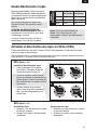
Zentrieren der Ruderfl ächen ...............................24
Einstellungen der Ruderhörner ............................24
Steuerrichtungstest ............................................24
Dual Rates and Expos .........................................25
DX4e und DX5e Expo Aktivierung
und Deaktivierung ...............................................25
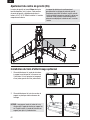
Einstellen des Schwerpunktes ............................26
Montage des optionalen Fahrwerkes ...................26
Tipps zum Fliegen und Reparieren ......................27
Installing Optional Cannons .................................28
Zusätzliche Sicherheitsvorkehrungen und
Warnhinweise .....................................................28
Wartung der Antriebskomponenten .....................29
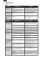
Problemlösung .................................................... 30
Problemlösung (Forstetzung) ...............................31
Garantie und Service Informationen ....................31
Garantie und Service Kontakt Informationen........32
Konformitätshinweise für die Europäische Union .33
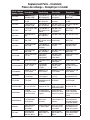
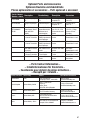
Ersatzteile ...........................................................66
Optionale Bauteile und Zubehörteile ....................67
Intaktinformationen für Ersatzteile ......................67
Motor: BL180m Impeller Motor,
11750Kv (EFLM30180mDFA)
Impeller Einheit: Delta-V 180m
28mm EDF Einheit (EFLDF180m)
Empfänger: Spektrum DSMX 6
Kanal AS3X Empfänger mit BL
Regler (SPMAS6410NBL)
Servo: (2) 2.3-Gram Performance
Linear Long Throw Servo
(SPMSA2030L)
(2) 2.3-Gram Linear Long Throw
Offset Servos (SPMSA2030LO)
Akku: 200mAh 2S 25C Li-Po
(EFLB2002S25)
Ladegerät: 2S 7.4V Li-Po
(EFLUC1007)
Empfohlener Sender:
Spektrum DSM2/DSMX mit
Dual-Rate (DX4e und aufwärts)
Wird noch benötigt:
Installiert:
402mm
412mm
77.5 g

20
DE
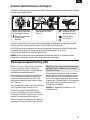
AS3X System liefert bahn-
brechende Leistung
Horizon Hobby hat immer schon RC Sport, Scale
und einzigartige Luftfahrzeuge entwickelt die
Experten überzeugen und lieben. Nun sorgt das
einzigartige AS3X Stabilisierungssystem für einen
Quantensprung in der Leistung der Ultra Micro
Flugzeuge.
Basierend auf der erfolgreichen Nutzung der
MEMS Sensor Technologie aus den Blade Ultra
Micro Fylbarless Helikoptern hilft das speziell für
Flugzeuge angepaßte System bei Turbulenzen,
bei dem Torquen und zur Vermeidung von
Strömungsabrissen.
Weiterhin liefert das System eine hochpräzise
Kontrolle mit dem sicheren Gefühl der absoluten
Neutralität. Dabei arbeitet es so überzeugend, dass
Sie das Gefühl haben ein perfekt abgestimmtes
Großmodell zu fliegen.
Das AS3X System wird die Art und Weise wie Sie
heute und in Zukunft fliegen wollen verändern. Um
zu sehen was wir damit meinen klicken Sie auf :
www.E-fliteRC.com/AS3X.
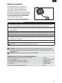
Vorbereitung für den Erstfl ug
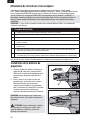
Akku Warnungen
Das im Lieferumfang enthaltene Ladegerät
(EFLUC1007) wurde für das sichere Laden der Li-Po
Akkus entwickelt.
ACHTUNG: Alle Anweisungen und
Warnhinweise müssen genau befolgt werden.
Falsche Handhabung von Li-Po-Akkus kann zu
Brand, Personen- und/oder Sachwertschaden
führen.
• Durch Handhaben, Aufl aden oder Verwenden des
inbegriffenen Li-Po-Akkus übernehmen Sie alle
mit Lithiumakkus verbundenen Risiken.
• Sollte der Akku beim Laden oder im Flug beginn-
en, sich auszudehnen oder anzuschwellen
stoppen Sie den Ladevorgang oder den Flug
unverzüglich. Ziehen Sie den Akkustecker, und
bringen Sie den Akku in eine sichere offene
Gegend, weit weg von entfl ammbaren Materialien,
und beobachten Sie ihn mindestens 15 Minuten.
Wird mit dem Aufl aden oder Entladen eines
Akkus fortgefahren, der sich auszudehnen oder
anzuschwellen begonnen hat, kann dies zu einem
Brand führen.
• Um beste Ergebnisse zu erzielen, lagern Sie
den Akku bei Raumtemperatur an einem
trockenen Ort.
• Beim Transport oder vorübergehenden Lagern
des Akkus sollte der Temperaturbereich zwischen
4°C und 49°C liegen. Bewahren Sie den Akku
bzw. das Modell nicht im Auto oder unter direkter
Sonneneinstrahlung auf. Bei Aufbewahrung in
einem heißen Auto, kann der Akku beschädigt
werden oder sogar Feuer fangen.
• Laden Sie immer den Akku weg von
entfl ammbaren Materialien.
• Überprüfen Sie immer den Akku vor dem Laden.
Laden Sie niemals defekte oder beschädigte
Akkus.
• Trennen Sie nach dem Laden immer den Akku
vom Ladegerät und lassen das Ladegerät
zwischen dem Laden abkühlen.
• Überwachen Sie während des Ladevorganges die
Temperatur des Akkus.
• VERWENDEN SIE NUR EIN SPEZIELL GEEIGNETES
LI-PO LADEGERÄT UM LI-PO AKKUS ZU LADEN.
Laden Sie den Akku mit einem nicht geeigneten
Ladegerät kann dieses zu Feuer, Personen- und
Sachschäden führen.
• Entladen Sie niemals Li-Po Zellen unter 3 Volt per
Zelle unter Last.
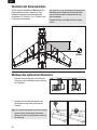
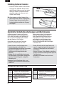
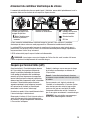
1. Laden Sie den Flugakku.
2. Setzen Sie den vollständig geladenen
Flugakku in das Flugakku ein.
3. Binden Sie das Flugzeug an den Sender.
4. Stellen Sie sicher, dass sich die Anlenkun-
gen frei bewegen können.
5. Führen Sie einen Steuerrichtungstest mit
dem Sender durch.
6. Stellen Sie die Dual Rates und Exponential
Werte ein.
7. Justieren Sie den Schwerpunkt.
8. Führen Sie einen Reichweitentest durch.
9. Finden Sie eine sichere und offenen Fläche
zum fl iegen.
10. Planen Sie Ihren Flug nach den Flugfeld-
bedingungen.
Seite wird geladen ...
Seite wird geladen ...
Seite wird geladen ...
Seite wird geladen ...
Seite wird geladen ...
Seite wird geladen ...
Seite wird geladen ...
Seite wird geladen ...
Seite wird geladen ...
Seite wird geladen ...
Seite wird geladen ...
Seite wird geladen ...
Seite wird geladen ...
Seite wird geladen ...
Seite wird geladen ...
Seite wird geladen ...
Seite wird geladen ...
Seite wird geladen ...
Seite wird geladen ...
Seite wird geladen ...
Seite wird geladen ...
Seite wird geladen ...
Seite wird geladen ...
Seite wird geladen ...
Seite wird geladen ...
Seite wird geladen ...
Seite wird geladen ...
Seite wird geladen ...
Seite wird geladen ...
Seite wird geladen ...
Seite wird geladen ...
Seite wird geladen ...
Seite wird geladen ...
Seite wird geladen ...
Seite wird geladen ...
Seite wird geladen ...
Seite wird geladen ...
Seite wird geladen ...
Seite wird geladen ...
Seite wird geladen ...
Seite wird geladen ...
Seite wird geladen ...
Seite wird geladen ...
Seite wird geladen ...
Seite wird geladen ...
Seite wird geladen ...
Seite wird geladen ...
Seite wird geladen ...
-
 1
1
-
 2
2
-
 3
3
-
 4
4
-
 5
5
-
 6
6
-
 7
7
-
 8
8
-
 9
9
-
 10
10
-
 11
11
-
 12
12
-
 13
13
-
 14
14
-
 15
15
-
 16
16
-
 17
17
-
 18
18
-
 19
19
-
 20
20
-
 21
21
-
 22
22
-
 23
23
-
 24
24
-
 25
25
-
 26
26
-
 27
27
-
 28
28
-
 29
29
-
 30
30
-
 31
31
-
 32
32
-
 33
33
-
 34
34
-
 35
35
-
 36
36
-
 37
37
-
 38
38
-
 39
39
-
 40
40
-
 41
41
-
 42
42
-
 43
43
-
 44
44
-
 45
45
-
 46
46
-
 47
47
-
 48
48
-
 49
49
-
 50
50
-
 51
51
-
 52
52
-
 53
53
-
 54
54
-
 55
55
-
 56
56
-
 57
57
-
 58
58
-
 59
59
-
 60
60
-
 61
61
-
 62
62
-
 63
63
-
 64
64
-
 65
65
-
 66
66
-
 67
67
-
 68
68


E-flite UMX MiG 15 DF Benutzerhandbuch
- Kategorie
- Ferngesteuertes Spielzeug
- Typ
- Benutzerhandbuch
in anderen Sprachen
- English: E-flite UMX MiG 15 DF User manual
- français: E-flite UMX MiG 15 DF Manuel utilisateur
- italiano: E-flite UMX MiG 15 DF Manuale utente
Verwandte Artikel
-
E-flite UMX PT-17 Benutzerhandbuch
-
E-flite Carbon-Z Cub Benutzerhandbuch
-
-
-
-
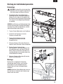
-
-
-
-
Andere Dokumente
-
Horizon Hobby UMX YAK 54 3D Benutzerhandbuch
-
Spektrum DX4 DSMX 4-Channel Full Range Tx only MD2/4 Bedienungsanleitung
-
Spektrum 2.3-Gram Linear Long Throw Offset Servo Bedienungsanleitung
-
ParkZone Extra 300 PNP/BNF Benutzerhandbuch
-
Blade Nano CP X Benutzerhandbuch
-
BNF P-51D Mustang 280 Benutzerhandbuch
-
-
-
Autel Robotics EVO Nano Series Benutzerhandbuch
-
 BlitzWolf US-BW-SL0 Benutzerhandbuch
