Teletek SensoIRIS M140 IS Benutzerhandbuch
- Kategorie
- Brandschutz
- Typ
- Benutzerhandbuch

Essential characteristics
Performance under fire conditions
Operational reliability
Performance
Pass
Pass
Temperature resistance
Humidity resistance
Corrosion resistance
Shock and vibrationresistance
Durability of operational reliability:
Pass
Pass
Pass
Pass
SensoIRIS M140 IS 4. Connect the detector base to the fire panel using the wiring diagram.
7. If the detector has been locked to the base, when open it for a service schedule maintenance and cleaning you have to use a
plain screw-driver. Light press with the screw-driver into the base opening and at the same time rotate the detector head counter-
clockwise.
Warranty
3. Mount the fire base on the ceiling of the protected premises using fixings according the mounting surface.
ATTENTION: Disconnect the loop power before installing the detector!
5. Insert the detector into the base and rotate clockwise until it drops into place - the short mark on the base fits with that on the
detector body. Continue to rotate the detector until the detector mark coincides with the long mark on the base - a click is heard.
ATTENTION: The blinking of the two LEDs can be managed from the control panel (ON/ OFF).To turn the blinking on/ off you have to
be a User with Access control level 3.
6. Test the detector for proper operation and LED indication.
Choose in consecutiveness from the control panel: System - Programming - Devices - Loop. Find the installed detector, as enter
address, loop and zone number - the panel automatically will recognize the type of the detector. Choose the button MORE to enter in
the additional settings menu and to review the SW version and ID number of the detector. The blinking of LEDs is turned on/ off with
pressing the ON/OFF button in the “Led Blink” field.
ATTENTION: Read carefully this installation Instructions before installing the device! This manual is subject to change
without notice!
SensoIRIS M140 IS is аn addressable combined (optical-smoke and heat) detector with built-in isolator module designed for installing
in addressable fire alarm systems supporting TTE communication protocol. The detector is powered on from the panel and can be
controlled via the communication protocol. The detector SensoIRIS M140 IS is compatible with fire bases B124 (low profile,
white/black color) and B124-HP (high profile, white color).
1. Choose the proper place for installation of the fire detector. Refer to the given installation instructions. Note: Do not install the
detector near sources of steam, condensation or smoke and close to natural heat sources.
Installation Instructions
2. If you want to “lock” the detector to the base remove the little “tooth” on the top of the locking mechanism (located in the narrow
part).
All detectors carry on a warranty valid from the date of manufacture. The date of manufacture can be checked by the code on the
back of the detector. The first two numbers represent the year and the last two - the month. For example: The date code “20 07”,
means the detector is manufactured in July, 2020.
To return goods for warranty service, please contact with your local distributer for details.
Todos los detectores poseen una garantía válida desde la fecha de fabricación. La fecha de fabricación se ha indicado en el dorso
del detector, con cifras: AA MM. Las primeras dos cifras representan el año, y las últimas dos cifras el mes de fabricación. Ejemplo:
“20 07” significa fecha de fabricación julio de 2020.
En caso de devolver productos para un servicio de garantía, diríjase a su distribuidor regional.
SensoIRIS M140 IS – Detector analógico combinado (de humo óptico y de temperatura) con aislador incorporado. El detector está
destinado a utilizarse en sistemas de alarma analógicos, que mantienen el protocolo de comunicación TTE. El detector recibirá
alimentación del panel y podrá ser controlado mediante el protocolo de comunicación. El detector SensoIRIS M140 IS es compatible
con las bases B124 (perfil bajo, color blanco/negro) y B124-HP (alto perfil, color blanco).
2. Si desea bloquear el detector en la base, retire la pestaña de la punta del mecanismo de cierre (en la parte estrecha).
ATENCIÓN: ¡Lea atentamente las instrucciones antes de proceder a instalar el detector! ¡El fabricante se reserva el
derecho de realizar cambios sin notificación previa!
ATENCIÓN: ¡Desconecte la alimentación del lazo antes de montar el detector!
Instrucciones de instalación
1. Seleccione un lugar apropiado para instalar el detector. Siga las instrucciones que se han dado para la instalación.
Observación: No instale el detector cerca de fuentes de calor naturales, por ejemplo, encima de cocinas, hornos o chimeneas.
3. Instale la base en el techo del local, seleccionando los tornillos y los tacos según la superficie de montaje.
4. Realice el montaje eléctrico, según el esquema adjunto.
5. Coloque el detector en la base y hágalo girar en el sentido de las agujas del reloj hasta que se introduzca en los canales guía: el
marcador corto de la base coincide con el del detector. Siga girando, hasta que el marcador del detector coincida con el marcador
largo de la base: se oirá un chasquido.
6. Pruebe si el detector y la indicación LED funcionan correctamente.
7. Si el detector está bloqueado en la base, para abrirlo con el propósito de su limpieza y mantenimiento deberá utilizar un
destornillador apropiado. Apriete ligeramente con el destornillador en la abertura de la base, y, simultáneamente, haga girar el
detector en el sentido inverso al de las agujas del reloj.
Seleccione sucesivamente en el panel: Sistema – Programar – Dispositivos – Lazo. Encuentre el detector instalado, determinando la
dirección, el número del lazo y de zona: el panel reconocerá automáticamente el tipo del dispositivo. Seleccione el pulsador MÀS
para entrar en el menú de ajustes adicionales y revisar la versión de software (SW) y el número de identificación (ID) del detector. El
parpadeo del diodo LED se conectará/desconectará al presionar el pulsador CONECT./DESCONECT. en el campo “Parpadeo del
diodo LED”.
Garantía
ATENCIÓN: El parpadeo de los diodos LED del detector podrá conectarse y desconectarse del panel de control. Para
conectar/desconectar el parpadeo de los diodos LED, Ud. deberá ser usuario con nivel de acceso 3.
ACHTUNG: Das Blinken der LED Leuchten des Rauchmelders kann über das Bedienfeld ein- und ausgeschaltet werden. Damit Sie das Blinken der LED
Leuchten ein-/ausschalten können, müssen Sie ein Benutzer der Zugangsstufe 3 sein.
Für Reparaturen oder Umtausch im Rahmen der Garantie wenden Sie sich bitte an Ihren lokalen Händler.
7. Wenn der Rauchmelder am Sockel verriegelt ist, verwenden Sie einen passenden Schraubendreher, um diesen zur Reinigung und Wartung zu
öffnen. Mit dem Schraubendreher in der Öffnung des Sockels leicht drücken und gleichzeitig den Rauchmelder gegen den Uhrzeigersinn drehen.
Wählen Sie im Bedienfeld folgende Elemente in der angegebenen Reihenfolge: System – Programmieren – Device – Loop. Den installierten Rauchmelder
durch Eingabe der Adresse, der Kreisnummer und der Zone finden – der Meldertyp wird automatisch anerkannt. Die Taste MEHR bedienen, um das Menü
mit den zusätzlichen Einstellungen zu öffnen und die SW-Version und die ID-Nummer des Detektors zu überprüfen. Das Blinken der LED Leuchten wird
durch Bedienen der Taste EIN/AUS im Feld “Blinken LED Leuchten“ ein/ausgeschaltet.
Garantie
Alle Rauchmelder verfügen über eine Garantie, die ab Herstellungsdatum gilt. Das Herstellungsdatum ist auf dem an der Rückseite des melders im
Format JJ MM angegeben. Die beiden ersten Ziffern stehen für das Jahr und die letzten zwei Ziffern für den Monat. Beispiel: “20 07“ bedeutet, dass der
Rauchmelder im Juli 2020 hergestellt worden ist.
6. Der Rauchmelder auf seinen einwandfreien Betrieb und auf Lichtindikation überprüfen.
ACHTUNG: Bitte lesen Sie diese Anleitung sorgfältig, bevor Sie mit der Installation beginnen! Der Hersteller behält sich das Recht auf
Änderungen ohne vorherige Ankündigung vor!
SensoIRIS M140 IS ist ein adressierbarer Kombinierter Melder (optischer Rauchmelder mit fixierter Auslösetemperatur) mit eingebautem Isolator für den
Einbau in adressierbare Brandmeldeanlagen mit TTE-Kommunikationsprotokoll. Der Melder wird von der Zentrale aus eingeschaltet und kann über das
Kommunikationsprotokoll gesteuert werden. Der Rauchmelder SensoIRIS M140 IS ist mit Feuersockelen B124 (Kompaktes Design, Farbe Weiß/Schwarz)
und B124-HP (Hohem Profil, Farbe Weiß) kompatibel.
2. Wenn Sie den Rauchmelder am Sockel “verriegeln” wollen, entfernen Sie die kleine “Nut” an der Oberseite des Verriegelungsmechanismus (im
verengten Bereich).
4. Die elektrische Installation erfolgt nach dem beigefügten Schaltplan.
1. Einen passenden Montageort für den Rauchmelder auswählen. Die angegebenen Installationsanweisungen beachten.
Installationsanleitung
3. Sockel an der Raumdecke mithilfe von Schrauben und Dübeln in Abhängigkeit von der Montagefläche befestigen.
ACHTUNG: Vor Installierung des Rauchmelders die Einspeisung für den Kreis ausschalten!
Hinweis: Den Sensor nicht in der Nähe von Dampf-, Rauch-, Staub- oder Wärmequellen, z. B. Kochfeldern, Kaminen installieren.
5. Den Rauchmelder in den Sockel einsetzen und im Uhrzeigersinn drehen, bis er in den Führungskanälen reinpasst – die kurze Markierung des Sockels
deckt sich mit der Markierung des Rauchmelders. Weiter drehen bis sich die Markierung des Rauchmelders mit der langen Markierung des Sockels deckt
und Sie das Klicken beim Einrasten hören.
1. Изберете подходящо място за монтаж на детектора. Следвайте дадените инструкции за инсталиране. Забележка: Не инсталирайте
детектора в близост до източници на пара, дим, прах или топлина - печки, камини и т.н .
Изберете последователно от панела: Система - Програмиране - Устройства - Кръгови. Намерете инсталирания детектор, като зададете адрес,
номер на кръг и зона - панела разпознава автоматично типа на устройството. - Кръгови. Намерете инсталирания детектор, като зададете адрес,
номер на кръг и зона - панела разпознава автоматично типа на устройството. Изберете бутон Друго, за да влезете в менюто за допълнителни
настройки, включително за проверка на софтуерната версия (SW) и идентификационния номер (ID) на детектора. Мигането на светодиода се
включва/ изключва с натискане на бутон ВКЛ./ИЗКЛ. в поле “Мигане на светодиода”.
Всички детектори притежават гаранция валидна от датата на производство. Датата на производство е изписана на гърба на детектора. Първите две
цифри представляват годината, а последните две - месеца на производство. Пример: “20 07”, означава дата на производство Юли 2020.
Инструкция за инсталиране
3. Монтирайте основата на тавана на помещението, като подберете винтове и дюбели според монтажната повърхност.
4. Извършете електрически монтаж съгласно приложената схема.
2. Ако желаете да “заключвате” детектора към основата отстранете зъбчето на върха на заключващия механизъм (в стеснената част).
ВНИМАНИЕ: Изключете захранването на контура преди да монтирате детектора!
5. Поставете детектора в основата и го завъртете по посока на часовниковата стрелка до попадане в направляващите канали - късият маркер на
основата съвпада с този на детектора. Продължете да въртите докато маркера на детектора съвпадне с дългия маркер на основата - чува се
щракване.
6. Тествайте детектора за правилна работа и светлинна индикация.
ВНИМАНИЕ: Прочетете внимателно инструкцията преди да пристъпите към инсталиране на детектора! Производителят си запазва
правото за промени без предизвестие!
7. Ако детекторът е заключен към основата, за да го отворите за почистване и поддръжка трябва да използвате подходяща отвертка. Леко
натиснете с отвертката в отвора на основата и едновременно с това завъртете детектора обратно на часовниковата стрелка.
Гаранция
ВНИМАНИЕ: Мигането на светодиодите на детектора може да се включва и изключва от контролния панел. За да включите/ изключите мигането на
светодиодите трябва да сте Потребител с Ниво на достъп 3.
SensoIRIS М140 IS е адресируем комбиниран (оптично-димен и температурен) детектор с вграден изолатор модул предназначен за използване в
адресируеми пожароизвестителни алармени системи, поддържащи комуникационен протокол TTE. Детекторът получава захранване от панела и
може да бъде контролиран чрез комуникационния протокол. Детектор SensoIRIS M140 IS е съвместим соснови B124 (нисък профил, бял/черен
цвят) и B124-HP (висок профил, бял цвят).
За да върнете изделия за гаранционен сервиз се обръщайте към вашия регионален дистрибутор.
Installation Instruction
Intelligent analogue addressable
fire alarm heat and optical smoke
detector with built-in isolator module
DoP No: 020
2831 22
Class (EN 54-5) . . . . . . . . . . . . . . . . . . . . . . . . . . . . . . . . . Klasse (EN 54-5) . . . . . . . . . . . . . . . . . . . . . . . . . . . . . . . . Clase (EN 54-5) . . . . . . . . . . . . . . . . . . . . . . . . . . . . . . . . . . . . . . . . . . Клас (EN 54-5) . . . . . . . . . . . . . . . . . . . . . . . . . . . . . . . . . . . . . . A1/R
Consumption in quiescent state, with communication . . . . Verbrauch im Ruhemodus, mit Kommunikation . . . . . . . . . Consumo en estado sin activar, con comunicación . . . . . . . . . . . . . . . Консумация в незадействано състояние, с комуниакция. . . . < 310μA@27VDC
Operating Voltage Range. . . . . . . . . . . . . . . . . . . . . . . . . . Versorgungsspannungsbereich .....................Voltaje de alimentación. . . . . . . . . . . . . . . . . . . . . . . . . . . . . . . . . . . . . Захранващо напрежение . . . . . . . . . . . . . . . . . . . . . . . . . . . . . 16 - 32VDC (Nom. 27VDC)
Consumption in quiescent state, no communication . . . . . Verbrauch im Ruhemodus, ohne Kommunikation . . . . . . . Consumo en estado sin activar, sin comunicación . . . . . . . . . . . . . . . . Консумация в незадействано състояние, без комуниакция. . < 190μA@27VDC
Consumption in alarm state, with communication . . . . . . . Verbrauch im Alarmmodus, mit Kommunikation . . . . . . . . Consumo en estado de alarma, con comunicación . . . . . . . . . . . . . . . Консумация в алармено състояние, с комуникация . . . . . . . . 6.5mA
Dimensions . . . . . . . . . . . . . . . . . . . . . . . . . . . . . . . . . . . . Abmessungen . . . . . . . . . . . . . . . . . . . . . . . . . . . . . . . . . . Dimensiones . . . . . . . . . . . . . . . . . . . . . . . . . . . . . . . . . . . . . . . . . . . . . Размери . . . . . . . . . . . . . . . . . . . . . . . . . . . . . . . . . . . . . . . . . . . 103х49mm
Output in alarm state at terminal RI (terminals 4/ 1) . . . . . Strom im Alarmmodus Klemme RI (Klemmen 4/ 1) . . . . . . Corriente eléctrica en estado de alarma del RI (terminales 4/1) . . . . . Ток в алармено състояние на клема RI (клеми 4/ 1). . . . . . . . 7.5 mA (max)/ 7.5V
- High/ *Normal/ Middle/ Low . . . . . . . . . . . . . . . . . . . . - Hoch/ *Normal/ Mittel/ Niedrig . . . . . . . . . . . . . . . . . . - Alto/ *Normal/ Medio/ Bajo . . . . . . . . . . . . . . . . . . . . . . . . . . . . . . - Висока/ *Нормална/ Средна/ Ниска
** Not tested by LPCB/ Nicht von LPCB getestet/ No probado por LPCB/ Не е тествано в LPCB
Relative humidity resistance . . . . . . . . . . . . . . . . . . . . . . . Beständigkeit gegen relative Luftfeuchtigkeit. . . . . . . . . . . Resistencia a humedad relativa . . . . . . . . . . . . . . . . . . . . . . . . . . . . . . Устойчивост на относителна влажност . . . . . . . . . . . . . . . . . . (93 ± 3)% @ 40°C
Sensitivity level (in accordance with EN54-7*). . . . . . . . . . Empfindlichkeitsstufe (entsprechend der EN 54-7*) . . . . . Nivel de sensibilidad (en conformidad con EN54-7*) . . . . . . . . . . . . . . Ниво на чувствителност (в съответствие с EN54-7*)
Degree of protection. . . . . . . . . . . . . . . . . . . . . . . . . . . . . . Schutzgrade . . . . . . . . . . . . . . . . . . . . . . . . . . . . . . . . . . . . Grado de protección . . . . . . . . . . . . . . . . . . . . . . . . . . . . . . . . . . . . . . . Степен на защита . . . . . . . . . . . . . . . . . . . . . . . . . . . . . . . . . . . IP30**
Technical Specifications / Technische Daten / Características Técnicas / Технически Характеристики
1407 Sofia, Bulgaria
EN 54-7:2018
CEA 4021:2003
EN 54-17:2005/ AC:2007
Teletek Electronics JSC
Detector Class A1/R
EN 54-5:2017+A1:2018
Address: 14A Srebarna Str,
1139m/01
Tested by
~125g
Indoor use /
Innenmontage /
Montaje interno /
Вътрешен монтаж
Outdoor use /
Außenmontage /
Montaje externo /
Външен монтаж
!
Without base/
Ohne Sockel/
peso sin base incluida /
без основа
Installation / Installation /
Instalación / Инсталиране
-10°C ÷ +60°C
2 2
0.4mm - 2.0mm
Isolator Module Technical Specifications / Technische Parameter des Isolators / Características técnicas del aislador / Технически характеристики на изолатора
Vmin.....Min. line voltage. . . . . . . . . . . . . . . . . . . . . . . . . . . . . . . . . . . . . Min. Spannung im Loop . . . . . . . . . . . . . . . . . . . . . . . . . . . . . . . . . . . . . . . . . . . . . . Voltaje mín. en el círculo .............................. ..............................Минимално напрежение в кръга 16V
Ic max ...Max. rated continuous current with the switch closed . . . . . . . . Max. Dauerstrom bei geschlossenem Schlüssel (ununterbrochenem Loop) . . . . . . Corriente continua máx. en llave cerrada (circuito continuo) ...Макс. продължителен ток при затворен ключ (непрекъснат кръг) ...0.7A
Vsc min . . Min. voltage at which the device reconnects** . . . . . . . . . . . . . Min. Spannung, bei der das Device den Loop wiederherstellt* . . . . . . . . . . . . . . . . Voltaje mín. en que el dispositivo restablecerá el círculo** . . . . Мин. напрежение, при което устройството възстановява кръга** . . . 5V
** Note: Switches from open to closed / Hinweis: Schaltet vom geschlossenen auf offenen Zustand / Observación: Conmuta de estado abierto a estado cerrado / Забележка Превключва от отворено към затворено състояние:
Vnom ....Nom. line voltage. . . . . . . . . . . . . . . . . . . . . . . . . . . . . . . . . . . . Auslegungsspannung im Loop . . . . . . . . . . . . . . . . . . . . . . . . . . . . . . . . . . . . . . . . . Voltaje nom. en el círculo ..............................Номинално напрежение в кръга ..............................28V
Vso min . . Min. voltage at which the device isolates* . . . . . . . . . . . . . . . . Min. Spannung, bei der das Device den Loop unterbricht* . . . . . . . . . . . . . . . . . . . Voltaje mín. en que el dispositivo interrumpirá el círculo* .....Мин. напрежение, при което устройството прекъсва кръга* . . . . . . . . 5.9V
II max . . . . Max. leakage current with the switch open (isolated state) . . . . Strom bei Lekage beim geöffneten Schlüssel (unterbrochener Loop) . . . . . . . . . . . Corriente de escape en llave abierta (circuito discontinuo). . . . . . . . . . . . . . . . . . . . . 16mAТок на утечка при отворен ключ (прекъснат кръг)
Zc max ...Max. series impedance with the switch closed . . . . . . . . . . . . . Max. Serienimpedanz bei geschlossenem Schlüssel (ununterbrochenem Loop). . . Impedancia máx. de serie en llave cerrada (circuito continuo) ..Макс. сериен импеданс при затворен ключ (непрекъснат кръг).....0.12Ω@28VDC; 0.15 @15VDCΩ
Vso max . . Max. voltage at which the device isolates* . . . . . . . . . . . . . . . . Max. Spannung, bei der das Device den Loop unterbricht* . . . . . . . . . . . . . . . . . . . Voltaje máx. en que el dispositivo interrumpirá el círculo* .....Макс. напрежение, при което устройството прекъсва кръга* . . . . . . . 7.5V
Is max . . . Max. rated switching current (e.g. under short circuit). . . . . . . . Max. Strom der Wahlleitung (z.B. beim Kurzschluss). . . . . . . . . . . . . . . . . . . . . . . . Corriente máx. conmutable (por ejemplo, en cortocircuito). . . . . . . . . . . . . . . . . . 1.8AМакс. комутируем ток (например при късо съединие)
* Note: Switches from closed to open / Schaltet vom geschlossenen zum offenen Zustand / Observación: Conmuta de estado cerrado a estado abierto / : Забележка Превключва от затворено към отворено състояние
Vmax ....Max. line voltage . . . . . . . . . . . . . . . . . . . . . . . . . . . . . . . . . . . . Max. Spannung im Loop . . . . . . . . . . . . . . . . . . . . . . . . . . . . . . . . . . . . . . . . . . . . . Voltaje máx. en el círculo ..............................Максимално напрежение в кръга .............................32V
Vsc max . . Max. voltage at which the device reconnects** . . . . . . . . . . . . Max. Spannung, bei der das Device den Loop wiederherstellt* . . . . . . . . . . . . . . . . Voltaje máx. en que el dispositivo restablecerá el círculo** . . . . Макс. напрежение, при което устройството възстановява кръга** . . . 6.7V
18020195, RevG, 12/ 2021
Color / Farbe / Color / Цвят
RAL 9016
White/
Weiß/
Blanco/
Бял
RAL 9005
Black/
Schwarz /
Negro/
Черен
EN Installationsanleitung
DE
Instrucciones de instalación
ES Инструкция за инсталиране
BG

2
3Wiring Diagram / Schaltplan / Esquema de conexión / Схема на свързване
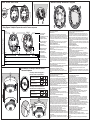
1Bases / Sockelen / Bases / Основи !Maintenance / Wartung / Mantenimiento / Поддръжка
4
4. Check and clean base and head contacts and connections -
annually.
The service maintenance of the detector should be provided:
3. Exert influence on the fire detector by smoke generator
(Aerosol Dispenser) or by aerosol simulator of smoke to test the
optical part; or use heat tester (Cordless Heat Detector Tester or
Heat Tester 110V>240V) at distance of 20 cm to test the heat
part. Within 8 sec the fire detector will enter in fire condition. Both
LEDs will light up.
4. Clean the chamber.
4. Power off the detector for 2 sec minimum. After resetting the
detector will enter in duty mode and the LEDs will light off.
5. Mount the PCB back to the detector’s body - as a reference
point use the side with a cut-out (3). Rotate the PCB until the cut-
out coincides with the pin on the inner part from the detector
body. Gently press the PCB down to fix in place.
1. Apply power to the detector.
1. Remove the detector from its base.
3. Check and clean dust contamination - six months.
2. Remove the inner protective cover - press the four clips (1)
with a plain screw-driver gently down to unlock the cover from the
detector’s body.
6. Mount the inner protective cover - the mark with a rectangular
shape (4) fits with the channel at the inner side of the detector’s
body and the contact plates on the PCB coincide with the four
openings on the protective cover. Press gently down until a click
is heard.
Test
2. Operational test in real conditions - monthly.
3. Dismount the PCB from the supporting clips (2).
1. Inspection for visible physical damage - weekly.
Cleaning and Maintenance
7. Mount the detector back to its base and test for correct
operation and LED indication.
2. Wait for 30 sec.
3. Die Platte aus den Clips (2) entnehmen.
3. Prophylaktische Reinigung von Staubverschmutzungen – alle sechs
Monate.
4. Prophylaktische Inspektion und Reinigung des Kontaktsystems –
jährlich.
2. Die innere Schutzabdeckung abnehmen. Mit einem passenden
Schraubendreher leicht die Clips (1) drücken, um diese vom
Rauchmeldergehäuse zu entriegeln.
4. Reinigen sie die Kamera des Sensors.
1. Visuelle Inspektion zur Feststellung von sichtbaren mechanischen
Beschädigungen – wöchentlich.
2. Betriebstest unter realen Bedingungen – monatlich.
4. Die Einspeisung des Rauchmelders für mindestens 2 Sekunden
unterbrechen. Nach diesem Zurücksetzen wird der Rauchmelder in
Dienstmodus übergehen und die beiden LED Leuchten gehen aus.
1. Rauchmelder an Spannung legen.
7. Den Rauchmelder wieder am Sockel einsetzen und den
einwandfreien Betrieb und die Anzeige überprüfen.
2. 30 Sekunden abwarten.
Die Wartung umfasst folgende Tätigkeiten:
1. Den Melder aus dem Sockel entnehmen.
5. Die Platte wieder ins Gehäuse montieren – zur Orientierung die
Seite mit dem Ausschnitt nach innen (3) verwenden. Die Platte so
drehen, dass sich der Ausschnitt mit dem Ausgangspunkt auf der
Innenseite des Meldergehäuses deckt. Die Platte aufmerksam nach
unten drücken, um diese zu befestigen.
Test
Reinigung und Wartung
3. Testen Sie den Sensor mit einem Rauchgenerator (Aerosol
Dispenser) oder einem anderen Aerosol Gerät, damit Sie die Optik
überprüfen; oder nutzen Sie einen Wärmetester (Cordless Heat
Detector Tester oder Heat Tester 110V>240V) auf den Sensor in
einem Abstand von 20 cm. Innerhalb von 8 Sekunden muss der
Rauchmelder in FEUER-Modus übergehen. Die beiden LED Leuchten
werden gleichzeitig aufleuchten.
6. Die innere Schutzabdeckung montieren. Die Markierung mit der
rechteckigen Form (4) muss sich mit der Nut an der inneren Seite des
Gehäuses und die Kontaktlamellen der Platte sich mit den vier
Öffnungen der Schutzabdeckung decken. Vorsichtig nach unten
drücken bis ein „Klick“ zu hören ist.
Fire Panel / Brandmeldepaneel /
Panel de alarma de incendio /
Пожароизвестителен панел
Earth
RI RI
+Loop
-Loop
-Loop
+Loop
B124 B124-HP
6
RI - Remote Indicator/
Signalleuchte
(Fernindikator über der Tür)
Indicador exterior/
Надвратен индикатор
+Loop - Positive loop wire/
Positiver Ausgang/
Bucle positivo/
Положителен извод
-Loop - Negative loop wire/
Negativer Ausgang/
Bucle negativo/
Отрицателен извод
Earth - Earth point/
Erdungsausgang/
Bucle de toma de tierra/
Заземителен извод
5LED Indication / LED Anzeige / Indicación luminosa /
Светлинна Индикация
Blinking/ Blinkt/ Parpadea/ Мига 10 sec OK
Light on/ Leuchtet/
Se ilumina/ Свети
Light off/ Leuchtet nicht/
No se ilumina/ Не свети
1. Blinking is enabled/ LED freigegeben /
Parpadeo activado/ Разрешено мигане
2. Blinking is disabled/ LED deaktivieren/
Parpadeo desactivado/ Забранено мигане
Light on/ Leuchtet/
Se ilumina/ Свети
Light off/ Leuchtet nicht/
No se ilumina/ Не свети
3. Профилактично почистване на замърсяване от прах- 6 месеца
4. Профилактична проверка и почистване на контактната система
- 1 година.
2. Изчакайте 30 сек.
1. Външен оглед за видими механични повреди - ежеседмично
3. Извадете платката от придържащите щипки (2).
1. Подайте захранващо напрежение на детектора.
Тест
Почистване и Поддръжка
1. Свалете детектора от основата.
2. Свалете вътрешния защитен капак - с подходяща отвертка
натиснете леко в щипките (1), за да ги отключите от корпуса на
детектора.
3. Въздействайте с генератор на дим (Aerosol Dispenser) или с
друго аерозолно устройство, за да тествате оптичната част; или
използвайте топлинен тестер (Cordless Heat Detector Tester или
Heat Tester 110V>240V) върху детектора от разстояние 20см. В
границите на 8 секунди след въздействието детектора трябва да
се установи в състояние “ПОЖАР”. Двата светодиода ще светнат
едновременно.
4. Прекъснете за 2 сек. минимум захранването на детектора. След
подобен ресет детектора ще се установи в дежурен режим и двата
светодиода ще изгаснат.
5. Монтирайте платката обратно към корпуса - използвайте за
ориентир страната с прорез навътре (3). Завъртете платката така,
че прореза да съвпадне с репера от вътрешната страна на
корпуса на детектора. Натиснете внимателно платката надолу, за
да я фиксирате на място.
6. Монтирайте вътрешния защитен капак - реперът с правоъгълна
форма (4) трябва да съвпадне с жлеба от вътрешната страна на
корпуса, а конктните пластини на платката - с четирите отвора на
защитния капак. Натиснете леко надолу докато се чуе щракване.
Сервизна поддръжка на детекторите трябва да се извършва:
4. Почистете камера на детектора.
2. Проверка на работоспособността в реални условия-
ежемесечно
7. Монтирайте детектора обратно към основата и тествайте за
работоспособност и индикация.
3. Saque el circuito de las pinzas de soporte (2).
Prueba
El mantenimiento de los detectores deberá efectuarse:
4. Interrumpa mínimo durante 2 segundos la alimentación del
detector. Después de un tal rearme, el detector pasará a modo de
reposo y ambos diodos LED se apagarán.
1. Suministre voltaje de alimentación al detector.
3. Limpieza preventiva por impurezas de polvo: cada 6 meses.
4. Limpie la cámara del detector.
2. Retire la tapa interna de protección: con un destornillador
apropiado, presione ligeramente en las pinzas (1) del cuerpo del
detector para abrirlas.
1. Retire el detector de la base.
2. Inspección de la capacidad de funcionamiento en condiciones
reales: cada mes.
1. Examen exterior por daños mecánicos visibles: cada semana.
3. Ejerza influencia con un generador de humo (Aerosol
Dispenser) o con otro dispositivo de aerosol para probar la parte
óptica; o bien utilice un ensayador térmico (Cordless Heat
Detector Tester o Heat Tester 110V>240V) sobre el detector
desde una distancia de 20 cm. En los límites de 8 segundos
después de haber ejercido la influencia sobre el detector, deberá
establecerse en estado de “INCENDIO”. Ambos diodos LED se
iluminarán simultáneamente.
Limpieza y Mantenimiento
7. Instale nuevamente el detector en la base, y ensaye la
capacidad de funcionamiento y la indicación.
2. Espere durante 30 segundos.
6. Instale la tapa de protección interna: el punto de referencia de
forma rectangular (4) deberá coincidir con el canal por la parte
interna del cuerpo, y, las placas de contacto del circuito, con las
cuatro aberturas de la tapa de protección. Presione ligeramente
hacia abajo, hasta que se oiga un chasquido.
5. Instale de nuevo el circuito en el cuerpo: utilice, a modo de
orientación, la parte con una ranura (3) hacia adentro. Haga girar
el circuito, de modo que la ranura coincida con el punto de
referencia de la parte interna del cuerpo del detector. Presione
cuidadosamente el circuito hacia abajo para fijarlo en el lugar.
4. Inspección preventiva y limpieza del sistema de contacto: 1 vez
al año.
B124 B124-HP
104x17.5mm103x11mm
-
 1
1
-
 2
2


Teletek SensoIRIS M140 IS Benutzerhandbuch
- Kategorie
- Brandschutz
- Typ
- Benutzerhandbuch
in anderen Sprachen
Verwandte Artikel

Andere Dokumente
-
PNI GD-01 Gas Detector Benutzerhandbuch
-
SensoMAG F10 B12L-U Bedienungsanleitung
-
Stanley STHT77587-0 Benutzerhandbuch
-
SensoMAG S30 Bedienungsanleitung
-
Certa FMR 4030 Quick Manual
-
BW Technologies BW Ultra Portable Five-gas Detector Benutzerhandbuch
-
Abus FUMK50020B Datenblatt
-
Marmitek Smoke Alarm SD833 Benutzerhandbuch
-
 Prestigio PCD Series User RoadRunner 565 Bedienungsanleitung
-
Alecto SA-41 Bedienungsanleitung
