Axis Q1910-E Thermal Network Camera Installationsanleitung
- Kategorie
- Sicherheitskameras
- Typ
- Installationsanleitung
Dieses Handbuch eignet sich auch für

ENGLISH DEUTSCH ITALIANO ESPAÑOL
INSTALLATION GUIDE
FRAN
Ç
AIS
AXIS Q1910 Thermal Network Camera
AXIS Q1910-E Thermal Network Camera

Legal Considerations
Video and audio surveillance can be prohibited by laws
that vary from country to country. Check the laws in
your local region before using this product for
surveillance purposes.
This product includes one (1) H.264 decoder license.
Trademark Acknowledgments
Apple, Boa, Bonjour, Ethernet, Internet Explorer, Linux,
Microsoft, Mozilla, Netscape Navigator, OS/2, Real,
SMPTE, QuickTime, UNIX, Windows, WWW are
registered trademarks of the respective holders. Java
and all Java-based trademarks and logos are trademarks
or registered trademarks of Sun Microsystems, Inc. in
the United States and other countries. Axis
Communications AB is independent of Sun
Microsystems Inc. UPnP™ is a certification mark of the
UPnP™ Implementers Corporation.
Electromagnetic Compatibility (EMC)
This equipment generates, uses and can radiate radio
frequency energy and, if not installed and used in
accordance with the instructions, may cause harmful
interference to radio communications. However, there is
no guarantee that interference will not occur in a
particular installation.
If this equipment does cause harmful interference to
radio or television reception, which can be determined
by turning the equipment off and on, the user is
encouraged to try to correct the interference by one or
more of the following measures: Re-orient or relocate
the receiving antenna. Increase the separation between
the equipment and receiver. Connect the equipment to
an outlet on a different circuit to the receiver. Consult
your dealer or an experienced radio/TV technician for
help. Shielded (STP) network cables must be used with
this unit to ensure compliance with EMC standards.
USA - This equipment has been tested and found to
comply with the limits for a Class B computing device
pursuant to Subpart B of Part 15 of FCC rules, which are
designed to provide reasonable protection against such
interference when operated in a commercial
environment. Operation of this equipment in a
residential area is likely to cause interference, in which
case the user at his/her own expense will be required to
take whatever measures may be required to correct the
interference.
Canada - This Class B digital apparatus complies with
Canadian ICES-003
Europe - This digital equipment fulfills the requirements
for radiated emission according to limit B of EN55022,
and the requirements for immunity according to
EN55024 residential and commercial industry.
Japan - This is a class B product based on the standard
of the Voluntary Control Council for Interference from
Information Technology Equipment (VCCI). If this is used
near a radio or television receiver in a domestic
environment, it may cause radio interference. Install and
use the equipment according to the instruction manual.
Australia - This electronic device meets the
requirements of the Radio communications
(Electromagnetic Compatibility) Standard AS/NZS
CISPR22:2002.
Korea - Class B: As this equipment has obtained EMC
registration for household use, it can be used in any area
including residential areas.
Safety
Complies to EN 60950-1 (IEC 60950-1), Safety of
Information Technology Equipment.
Equipment Modifications
This equipment must be installed and used in strict
accordance with the instructions given in the user
documentation. This equipment contains no
user-serviceable components. Unauthorized equipment
changes or modifications will invalidate all applicable
regulatory certifications and approvals.
Liability
Every care has been taken in the preparation of this
document. Please inform your local Axis office of any
inaccuracies or omissions. Axis Communications AB
cannot be held responsible for any technical or
typographical errors and reserves the right to make
changes to the product and documentation without
prior notice. Axis Communications AB makes no
warranty of any kind with regard to the material
contained within this document, including, but not
limited to, the implied warranties of merchantability
and fitness for a particular purpose. Axis
Communications AB shall not be liable nor responsible
for incidental or consequential damages in connection
with the furnishing, performance or use of this material.
RoHS
This product complies with both the European
RoHS directive, 2002/95/EC, and the Chinese
RoHS regulations, ACPEIP.
WEEE Directive
The European Union has enacted a Directive
2002/96/EC on Waste Electrical and Electronic
Equipment (WEEE Directive). This directive is
applicable in the European Union member
states.
The WEEE marking on this product (see right) or its
documentation indicates that the product must not be
disposed of together with household waste. To prevent
possible harm to human health and/or the environment,
the product must be disposed of in an approved and
environmentally safe recycling process. For further
information on how to dispose of this product correctly,
contact the product supplier, or the local authority
responsible for waste disposal in your area.
Business users should contact the product supplier for
information on how to dispose of this product correctly.
This product should not be mixed with other commercial
waste.
Support
Should you require any technical assistance, please
contact your Axis reseller. If your questions cannot be
answered immediately, your reseller will forward your
queries through the appropriate channels to ensure a
rapid response. If you are connected to the Internet, you
can:
• download user documentation and firmware updates
• find answers to resolved problems in the FAQ database.
Search by product, category, or phrases
• report problems to Axis support by logging in to your
private support area.

AXIS Q1910/Q1910-E Installation Guide Page 3
ENGLISH
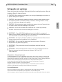
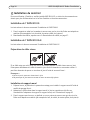
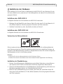
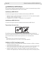
Safeguards and warnings
Please read through this Installation Guide carefully before installing the product. Keep the
Installation Guide for further reference.
Safety Notice - Battery Replacement
The AXIS Q1910/Q1910-E uses a 3.0V CR2032 Lithium battery as the power supply for its internal real-
time clock (RTC). Under normal conditions this battery will last for a minimum of 5 years. Low battery
power affects the operation of the RTC, causing it to reset at every power-up. A log message will appear
when the battery needs replacing. The battery should not be replaced unless required!
• If the battery does need replacing, please contact www.axis.com/techsup for assistance.
• Danger of Explosion if battery is incorrectly replaced
• Replace only with the same or equivalent battery, as recommended by the manufacturer.
• Dispose of used batteries according to the manufacturer's instructions.
Care and Maintenance
• Do not use chemicals, caustic agents, or aerosol cleaners. Use a damp cloth for cleaning.
• Only use accessories and replacement parts provided or recommended by Axis.
• Do not attempt to repair the product by yourself, contact Axis or your Axis reseller for service matters.
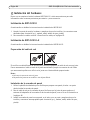
!CAUTION! - When transporting the camera, use the original packaging or equivalent to
prevent damage to the product.
!CAUTION! - Avoid exposing the camera to vibration, shocks or heavy pressure and do
not install the camera on unstable brackets, unstable or vibrating surfaces or walls,
since this could cause damage to the product.
!CAUTION! - Only use handtools when installing the camera, the use of electrical tools
or excessive force could cause damage to the product.
!CAUTION! - Do not aim the camera lens toward the sun or other high-intensity
radiation sources since this could cause damage to the sensor.
!IMPORTANT! - To use AXIS Q1910 outdoors, it must be installed in an approved
outdoor housing. Please install AXIS Q1910-E for outdoor use or see www.axis.com for
more information on outdoor housing and other accessories.
!IMPORTANT! - The camera should be installed by a trained professional. Please observe
relevant national and local regulations for the installation.
!IMPORTANT! - Do not install the camera near heat sources since fluctuating
temperatures may affect image quality.
!IMPORTANT! - This product must be used in compliance with local laws and
regulations.
!IMPORTANT! - Store and transport the camera in a dry and ventilated environment.
Keep the storage and operating temperature between -40ºC and 50ºC
(-40ºF and122ºF).


AXIS Q1910/Q1910-E Installation Guide Page 5
ENGLISH
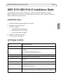
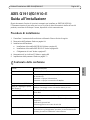
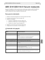
AXIS Q1910/Q1910-E Installation Guide
This installation guide provides instructions for installing an AXIS Q1910/Q1910-E Thermal
Network Camera on your network. For all other aspects of using the product, please see the User’s
Manual, available from www.axis.com
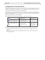
Installation steps
1. Check the package contents against the list below.
2. Hardware overview. See page 6.
3. Install the hardware.
• Install AXIS Q1910. See page 8.
• Install AXIS Q1910-E. See page 8.
• Connect the cables. See page 9.
4. Assign an IP address. See page 10.
5. Set the password. See page 13.
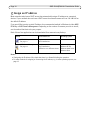
Package contents
Item Models/variants/notes
Network camera AXIS Q1910/Q1910-E
Terminal block connector 4-pin connector for connecting external devices to the I/O terminal
connector
3-pin connector for power connection
2-pin connector for RS-485/422 connection
Camera stand (AXIS Q1910) Metal stand supplied with mounting screws
Wall bracket (AXIS Q1910-E) Wall bracket with internal cable channel
Tools (AXIS Q1910-E) Torx T20 Screwdriver
Allen key
Network cable (AXIS Q1910-E) Outdoor network cable 5 m (16 ft.) with gasket
Printed materials AXIS Q1910/Q1910-E Installation Guide (this document)
Axis Warranty Document
Extra serial number labels (2x)
Optional accessories See www.axis.com for information on power accessories and outdoor
housings, product documentation, installation tools and other software.

Page 6 AXIS Q1910/Q1910-E Installation Guide
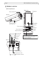
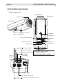
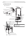
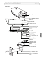
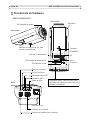
Hardware overview
Part number (P/N) & Serial number (S/N).
The serial number may be required
during the installation.
Connector (not used)
Button (not used)
1/4” screw mount for
wall/ceiling stand
Window heater connector
LED (not used)
Status indicator LED
Network connector
Audio in
Audio out
SD card slot
Power connector
Power indicator LED
Network indicator LED
Control
button
I/O
connector
RS-485/422
connector
Microphone
AXIS Q1910/Q1910-E
Rear view
Bottom view
Side view

AXIS Q1910/Q1910-E Installation Guide Page 7
ENGLISH
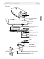
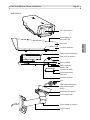
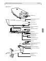
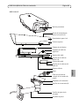
AXIS Q1910-E
Sun shield adjustment
Sun shield
Top cover
Thermal network camera
Bottom cover
Cable cover
Bottom cover screws (4x)
Cable cover screws (4x)
Cable holes
Safety wire tab
Protective window
Network cable (route
Wall bracket
Bracket adjustment screw
through wall bracket)
Gasket
Bracket adapter
screw (2x)
Bracket screws (4x)

Page 8 AXIS Q1910/Q1910-E Installation Guide
Install the hardware
For outdoor use, please install AXIS Q1910-E, or see www.axis.com for more information on
outdoor housing and other accessories.
Install AXIS Q1910
The instructions below describe the installation of AXIS Q1910.
1. Attach the metal stand to the camera and make sure that the screws and plugs are appropriate
for the material (e.g. wood, metal, sheet rock, stone).
2. Connect the cables, see
Connect the cables,
on page 9.
Install AXIS Q1910-E
The instructions below describe the installation of AXIS Q1910-E.
Prepare the network cable
If a cable other than the provided cable is used, you need to prepare a network cable with a gasket.
Gently force the cable through the gasket provided and attach a network connector. It may be
necessary to pierce a hole in the gasket with the supplied screwdriver.
Notes:
• Do not force the network connector into the gasket.
• Do not pierce the gasket with a knife or other sharp object.
Install the wall bracket
1. Use the supplied drill template to prepare a wall, ceiling, or pole for installation of the wall
bracket.
2. Route the network cable through the wall bracket, the rubber gasket should be on the bracket
adapter end of the wall bracket, see illustration on page 7.
3. Install the wall bracket on a wall, ceiling, or pole and make sure that the screws and plugs are
appropriate for the material (e.g. wood, metal, sheet rock, stone).

AXIS Q1910/Q1910-E Installation Guide Page 9
ENGLISH
Install the camera on the bracket
1. Install the camera with the bottom cover on the bracket and tighten the bracket screws.
2. Remove the gasket from one of the holes in the bottom cover, see illustration on page 7.
3. Route the cable through the hole and attach the cable gasket to the hole.
4. Connect the cables, see
Connect the cables,
on page 9.
5. Take the top cover and attach the safety wire to the tab on the bottom cover.
6. Connect the window heater to the window heater connector on the thermal camera.
7. Install the top cover and tighten the bottom cover screws.
8. Install the cable cover and tighten the cable cover screws.
9. Loosen the sun screen adjustment screws and adjust the sun shield to the front position.
10. Loosen the bracket adjustment screw to aim the camera to the point of interest. See
Access the
video stream,
on page 14 for information on how to view the video stream.
Connect the cables
1. Optionally insert an SD memory card (not included) into the SDHC (Secure Digital High
Capacity) card slot. A standard or high capacity SD card is required to store images locally in
the camera.
2. Optionally connect external input/output devices. See page 17 for information on the terminal
connector pins.
3. Optionally connect an active speaker and/or external microphone.
4. Connect the camera to the network using a shielded network cable.
5. Connect power, using one of the methods listed below:
• PoE (Power over Ethernet, Class 3). If available, this is automatically detected when the
network cable is connected.
• Connect an external power adapter to the power connector block, see
Unit connectors,
on
page 17 for wiring information.
6. Check that the indicator LEDs indicate the correct conditions. See the table on page 19 for
further details.

Page 10 AXIS Q1910/Q1910-E Installation Guide
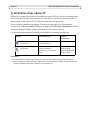
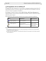
Assign an IP address
Most networks today have a DHCP server that automatically assigns IP addresses to connected
devices. If your network does not have a DHCP server the network camera will use 192.168.0.90 as
the default IP address.
If you would like to assign a static IP address, the recommended method in Windows is either AXIS
IP Utility or AXIS Camera Management. Depending on the number of cameras you wish to install,
use the method that best suits your purpose.
Both of these free applications can be downloaded from www.axis.com/techsup
Notes:
• If assigning the IP address fails, check that there is no firewall blocking the operation.
• For other methods of assigning or discovering the IP address, e.g. in other operating systems, see
page 15.
Method Recommended for Operating system
AXIS IP Utility
See page 11
Single camera
Small installations
Windows
AXIS Camera Management
See page 12
Multiple cameras
Large installations
Installation on a different subnet
Windows 2000
Windows XP Pro
Windows 2003 Server
Windows Vista

AXIS Q1910/Q1910-E Installation Guide Page 11
ENGLISH
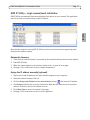
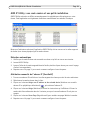
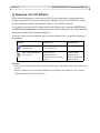
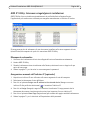
AXIS IP Utility - single camera/small installation
AXIS IP Utility automatically discovers and displays Axis devices on your network. The application
can also be used to manually assign a static IP address.
Note that the computer running AXIS IP Utility must be on the same network segment (physical
subnet) as the network camera.
Automatic discovery
1. Check that the network camera is connected to the network and that power has been applied.
2. Start AXIS IP Utility.
3. When the camera appears in the window, double-click it to open its home page.
4. See page 13 for instructions on how to assign the password.
Assign the IP address manually (optional)
1. Acquire an unused IP address on the same network segment as your computer.
2. Select the network camera in the list.
3. Click the Assign new IP address to the selected device button and enter the IP address.
4. Click Assign and follow the on-screen instructions. Note that the camera must be restarted
within 2 minutes for the new IP address to be set.
5. Click Home Page to access the camera’s web pages.
6. See page 13 for instructions on how to set the password.

Page 12 AXIS Q1910/Q1910-E Installation Guide
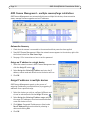
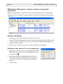
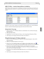
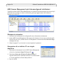
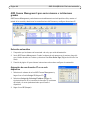
AXIS Camera Management - multiple cameras/large installations
AXIS Camera Management can automatically discover multiple Axis devices, show connection
status, manage firmware upgrades and set IP addresses.
Automatic discovery
1. Check that the camera is connected to the network and that power has been applied.
2. Start AXIS Camera Management. When the network camera appears in the window, right-click
the link and select Live View Home Page.
3. See page 13 for instructions on how to set the password.
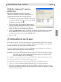
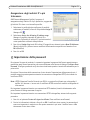
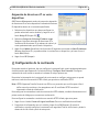
Assign an IP address in a single device
1. Select the network camera in AXIS Camera Management and
click the Assign IP button.
2. Select Assign the following IP address and enter the IP
address, subnet mask and default router the device will use.
3. Click OK.
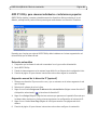
Assign IP addresses in multiple devices
AXIS Camera Management speeds up the process of
assigning IP addresses to multiple devices, by suggesting IP
addresses from a specified range.
1. Select the devices you wish to configure (different mod-
els can be selected) and click the Assign IP button.
2. Select Assign the following IP address range and enter
the range of IP addresses, the subnet mask and default
router the devices will use.
3. Click Update. Suggested IP addresses are listed under
New IP Addresses and can be edited by selecting a
device and clicking Edit.
4. Click OK.

AXIS Q1910/Q1910-E Installation Guide Page 13
ENGLISH
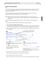
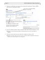
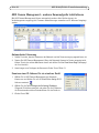
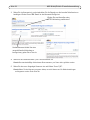
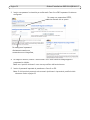
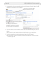
Set the password
To gain access to the product, the password for the default administrator user root must be set. This
is done in the ‘Configure Root Password’ dialog, which is displayed when the network camera is
accessed for the first time.
To prevent network eavesdropping when setting the root password, this can be done via an
encrypted HTTPS connection, which requires an HTTPS certificate.
Note: HTTPS (Hypertext Transfer Protocol over SSL) is a protocol used to encrypt the traffic
between web browsers and servers. The HTTPS certificate controls the encrypted exchange of
information.
To set the password via a standard HTTP connection, enter it directly in the first dialog shown
below.
To set the password via an encrypted HTTPS connection, follow these steps:
1. Click the Create self-signed certificate button.
2. Provide the requested information and click OK. The certificate is created and the password can
now be set securely. All traffic to and from the network camera is encrypted from this point on.
3. Enter a password and then re-enter it to confirm the spelling. Click OK. The password has now
been configured.
4. To log in, enter the user name “root” in the dialog as requested.
Note: The default administrator user name root cannot be deleted.
5. Enter the password as set above, and click OK.
Note: If the password is lost, the camera must be reset to the factory default settings. See page 20.
To configure the password directly
via an unencrypted connection, enter
the password here.
To create an HTTPS connection,
start by clicking this button.

Page 14 AXIS Q1910/Q1910-E Installation Guide
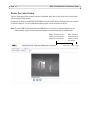
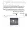
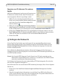
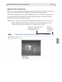
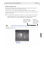
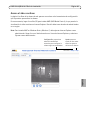
Access the video stream
The Live View page of the network camera is displayed, with links to the Setup tools, which allow
you to customize the camera.
If required, click Yes to install AMC (AXIS Media Control), which allows viewing of the video stream
in Internet Explorer. You will need administrator rights on the computer to do this.
Note: To install AMC in Windows Vista and Windows 7, you must run Internet Explorer as an
administrator. Right-click the Internet Explorer icon and select Run as administrator.
Setup - Provides all the
tools for configuring the
camera to requirements.
Help - Displays
online help on all
aspects of using
the camera.

AXIS Q1910/Q1910-E Installation Guide Page 15
ENGLISH
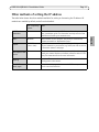
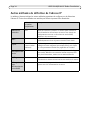
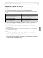
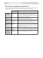
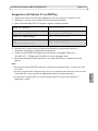
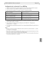
Other methods of setting the IP address
The table below shows the other methods available for setting or discovering the IP address. All
methods are enabled by default, and all can be disabled.
Use in operating
system
Notes
AVHS Service
Connection
All To connect the camera to an AVHS server, refer to the server pro-
vider´s Installation guide. For information and help to find a local
AVHS Service Provider go to www.axis.com
UPnP™ Windows When enabled on your computer, the camera is automatically
detected and added to “My Network Places.”
Bonjour MAC OSX
(10.4 or later)
Applicable to browsers with support for Bonjour. Navigate to the
Bonjour bookmark in your browser (e.g. Safari) and click on the link
to access the camera’s web pages.
AXIS Dynamic DNS
Service
All A free service from Axis that allows you to quickly and simply
install your camera. Requires an Internet connection with no HTTP
proxy. See www.axiscam.net for more information.
ARP/Ping All See below. The command must be issued within 2 minutes of con-
necting power to the camera.
View DHCP server
admin pages
All To view the admin pages for the network DHCP server, see the
server’s own documentation.

Page 16 AXIS Q1910/Q1910-E Installation Guide
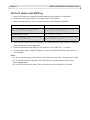
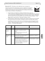
Set the IP address with ARP/Ping
1. Acquire an IP address on the same network segment your computer is connected to.
2. Locate the serial number (S/N) on the product label on the camera.
3. Open a command prompt on your computer and enter the following commands:
4. Check that the network cable is connected to the camera and then start/restart the camera, by
disconnecting and reconnecting power.
5. Close the command prompt when you see ‘Reply from 192.168.0.125: ...’ or similar.
6. In your browser, type in http://<IP address> in the Location/Address field and press Enter on
your keyboard.
Notes:
• To open a command prompt in Windows: from the Start menu, select Run... and type cmd. Click OK.
• To use the ARP command in WIndows Vista, right-click the command prompt icon and select
Run as administrator.
• To use the ARP command on a Mac OS X, use the Terminal utility in Application > Utilities.
Windows syntax: Windows example:
arp -s <IP Address> <Serial Number>
ping -l 408 -t <IP Address>
arp -s 192.168.0.125 00-40-8c-18-10-00
ping -l 408 -t 192.168.0.125
UNIX/Linux/Mac syntax: UNIX/Linux/Mac example:
arp -s <IP Address> <Serial Number> temp
ping -s 408 <IP Address>
arp -s 192.168.0.125 00:40:8c:18:10:00 temp
ping -s 408 192.168.0.125

AXIS Q1910/Q1910-E Installation Guide Page 17
ENGLISH
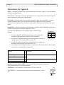
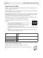
Unit connectors
Network - RJ-45 Ethernet connector. Supports PoE (Power over Ethernet, class 3). Using shielded
cables is recommended.
Audio in - 3.5mm input for a mono microphone, or a line-in mono signal (left channel is used from
a stereo signal).
Audio out - 3.5mm output for audio (line level), can be connected to a public address (PA) system
or an active speaker with a built-in amplifier. A pair of headphones can also be connected. A stereo
connector must be used for audio out.
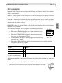
RS-485/422 - two 2-pin terminal blocks for RS-485/422 serial interface used to control auxiliary
equipment, e.g. PTZ devices.
The RS-485/422 serial port can be configured in the following port modes:
• Bidirectional RS-485 half-duplex port for data transmission using
two wires, one combined RX/TX pair.
• Bidirectional RS-485 full-duplex port for data transmission using
four wires, one RX pair and one TX pair.
• Unidirectional RS-422 port for transmitting or receiving data using
two wires, RX- or TX pair.
• Bidirectional RS-422 full-duplex port for data transmission (point-to-point) using four
wires, one RX pair and one TX pair.
SDHC memory card slot - High capacity SD memory card used for local recording and removable
storage.
Power - 3-pin terminal block 8-20 VDC or 20-24 VAC
Function Pin Notes
RS 485/422TX(A) 1 TX pair for RS-422 and 4-wire RS-485
RS 485/422TX(B) 2
RS-485A alt RS-485/422RX(A) 3 RX pair for all modes (combined RX/TX for 2-wire RS-485)
RS-485B alt RS-485/422RX(B) 4
!CAUTION! - Incorrect connection of the wires could cause damage to the camera.
4
321
RS-485/422
RX/TX TX
DC
AC

Page 18 AXIS Q1910/Q1910-E Installation Guide
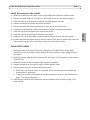
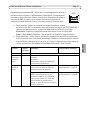
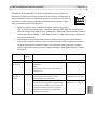
I/O terminal connector - Used in applications for e.g. motion detection, event
triggering, time lapse recording and alarm notifications. In addition to an
auxiliary power and a GND pin, the network camera has 2 pins that can be
configured as either input or output. These pins provide the interface to:
• Transistor output - For connecting external devices such as relays and
LEDs. Connected devices can be activated by AXIS VAPIX API, output
buttons on the Live View page or by an Event Type. The output will show as active (shown
under Events > Port Status) if the alarm device is activated.
• Digital input - An alarm input for connecting devices that can toggle between an open and
closed circuit, for example: PIRs, door/window contacts, glass break detectors, etc. When a
signal is received the state changes and the input becomes active (shown under
Events > Port Status.)
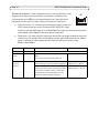
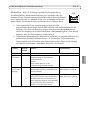
Function Pin number Notes Specifications
GND 1 Ground
3.3V DC
Power
2 Can be used to power auxiliary equipment.
Note:
This pin can only be used as power out.
Max load = 250mA
Configurable
(Input or
Output)
3 - 4 Digital input - Connect to GND to activate, or
leave floating (or unconnected) to deactivate.
Min input = - 40V DC
Max input = + 40V DC
Digital output - Uses an open-drain NFET
transistor with the source connected to GND.
If used with an external relay, a diode must
be connected in parallel with the load, for
protection against voltage transients.
Max load = 100mA
Max voltage = + 40V DC
4321
I/O

AXIS Q1910/Q1910-E Installation Guide Page 19
ENGLISH
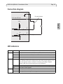
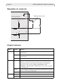
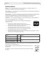
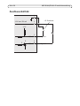
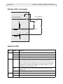
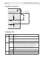
Connection diagram
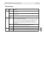
LED indicators
LED Color Indication
Network Green Steady for connection to a 100 Mbit/s network. Flashes for network activity.
Amber Steady for connection to 10 Mbit/s network. Flashes for network activity.
Unlit No network connection.
Status Green Steady green for normal operation.
Note: The Status LED can be configured to be unlit during normal operation, or to
flash only when the camera is accessed. To configure, go to Setup > System
Options > LED. See the online help files for more information.
Amber Steady during startup, during reset to factory default or when restoring settings.
Red Slow flash for failed upgrade.
Power Green Normal operation.
Amber Flashes green/amber during firmware upgrade.
3.3 V max 250 mA
1
2
3
4
E.g. push button
D
S
G
I/O configured as input
I/O configured as output
3.3V

Page 20 AXIS Q1910/Q1910-E Installation Guide
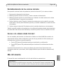
Resetting to the Factory Default Settings
This will reset all parameters, including the IP address, to the Factory Default settings:
1. Disconnect power from the camera.
2. Press and hold the Control button and reconnect power.
3. Keep the Control button pressed until the Status indicator displays amber (this may take up to
15 seconds).
4. Release the Control button. When the Status indicator displays green (which can take up to 1
minute) the process is complete and the camera has been reset.
5. Re-assign the IP address, using one of the methods described in this document.
It is also possible to reset parameters to the original factory default settings via the web interface.
For more information, please see the online help or the user’s manual.
Accessing the camera from the Internet
Once installed, your network camera is accessible on your local network (LAN). To access the
camera from the Internet, network routers must be configured to allow incoming traffic, which is
usually done on a specific port.
• HTTP port (default port 80) for viewing and configuration
• RTSP port (default port 554) for viewing H.264 video streams
Please refer to the documentation for your router for further instructions. For more information on
this and other topics, visit the Axis Support Web at www.axis.com/techsup
Further information
The user’s manual is available from the Axis Web site at www.axis.com.
Tip!
Visit www.axis.com/techsup to check if there is updated firmware available for your network
camera. To see the currently installed firmware version, see Setup > About.
Seite wird geladen ...
Seite wird geladen ...
Seite wird geladen ...
Seite wird geladen ...
Seite wird geladen ...
Seite wird geladen ...
Seite wird geladen ...
Seite wird geladen ...
Seite wird geladen ...
Seite wird geladen ...
Seite wird geladen ...
Seite wird geladen ...
Seite wird geladen ...
Seite wird geladen ...
Seite wird geladen ...
Seite wird geladen ...
Seite wird geladen ...
Seite wird geladen ...
Seite wird geladen ...
Seite wird geladen ...
Seite wird geladen ...
Seite wird geladen ...
Seite wird geladen ...
Seite wird geladen ...
Seite wird geladen ...
Seite wird geladen ...
Seite wird geladen ...
Seite wird geladen ...
Seite wird geladen ...
Seite wird geladen ...
Seite wird geladen ...
Seite wird geladen ...
Seite wird geladen ...
Seite wird geladen ...
Seite wird geladen ...
Seite wird geladen ...
Seite wird geladen ...
Seite wird geladen ...
Seite wird geladen ...
Seite wird geladen ...
Seite wird geladen ...
Seite wird geladen ...
Seite wird geladen ...
Seite wird geladen ...
Seite wird geladen ...
Seite wird geladen ...
Seite wird geladen ...
Seite wird geladen ...
Seite wird geladen ...
Seite wird geladen ...
Seite wird geladen ...
Seite wird geladen ...
Seite wird geladen ...
Seite wird geladen ...
Seite wird geladen ...
Seite wird geladen ...
Seite wird geladen ...
Seite wird geladen ...
Seite wird geladen ...
Seite wird geladen ...
Seite wird geladen ...
Seite wird geladen ...
Seite wird geladen ...
Seite wird geladen ...
Seite wird geladen ...
Seite wird geladen ...
Seite wird geladen ...
Seite wird geladen ...
Seite wird geladen ...
Seite wird geladen ...
Seite wird geladen ...
Seite wird geladen ...
Seite wird geladen ...
Seite wird geladen ...
Seite wird geladen ...
Seite wird geladen ...
Seite wird geladen ...
Seite wird geladen ...
Seite wird geladen ...
Seite wird geladen ...
Seite wird geladen ...
Seite wird geladen ...
-
 1
1
-
 2
2
-
 3
3
-
 4
4
-
 5
5
-
 6
6
-
 7
7
-
 8
8
-
 9
9
-
 10
10
-
 11
11
-
 12
12
-
 13
13
-
 14
14
-
 15
15
-
 16
16
-
 17
17
-
 18
18
-
 19
19
-
 20
20
-
 21
21
-
 22
22
-
 23
23
-
 24
24
-
 25
25
-
 26
26
-
 27
27
-
 28
28
-
 29
29
-
 30
30
-
 31
31
-
 32
32
-
 33
33
-
 34
34
-
 35
35
-
 36
36
-
 37
37
-
 38
38
-
 39
39
-
 40
40
-
 41
41
-
 42
42
-
 43
43
-
 44
44
-
 45
45
-
 46
46
-
 47
47
-
 48
48
-
 49
49
-
 50
50
-
 51
51
-
 52
52
-
 53
53
-
 54
54
-
 55
55
-
 56
56
-
 57
57
-
 58
58
-
 59
59
-
 60
60
-
 61
61
-
 62
62
-
 63
63
-
 64
64
-
 65
65
-
 66
66
-
 67
67
-
 68
68
-
 69
69
-
 70
70
-
 71
71
-
 72
72
-
 73
73
-
 74
74
-
 75
75
-
 76
76
-
 77
77
-
 78
78
-
 79
79
-
 80
80
-
 81
81
-
 82
82
-
 83
83
-
 84
84
-
 85
85
-
 86
86
-
 87
87
-
 88
88
-
 89
89
-
 90
90
-
 91
91
-
 92
92
-
 93
93
-
 94
94
-
 95
95
-
 96
96
-
 97
97
-
 98
98
-
 99
99
-
 100
100
-
 101
101
-
 102
102


Axis Q1910-E Thermal Network Camera Installationsanleitung
- Kategorie
- Sicherheitskameras
- Typ
- Installationsanleitung
- Dieses Handbuch eignet sich auch für
in anderen Sprachen
Verwandte Artikel
-
Axis Q1921-E Installationsanleitung
-
Axis Q1922 Installationsanleitung
-
-
-
Axis Communications M7001 Benutzerhandbuch
-
-
Axis Communications M7010 Benutzerhandbuch
-
Axis Communications Q7401 Benutzerhandbuch