
Assembly Instructions
Premium Server & Network Cabinets
Montageanleitung für
Server- und Netzwerkschränke
der Premium Line
intellinetnetwork.com

2 l Assembly Instructions | Montageanleitung
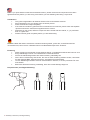
Note: If you purchased this cabinet as assembled version, please check that all components have been
tightened securely before you start using it and before you start installing networking components.
Introduction
• This guide is applicable to all Intellinet Premium Server & Network Cabinets
• Some illustrations may vary slightly from the actual product
• Follow all instruction steps completely
• If the cabinet includes any parts that are not described in this manual, please check the separate
“Special Instructions” sheet that is supplied with the cabinet.
• Depending on the model, different components are included with this cabinet, e. g. a perforated
door or a glass door
• Please read this guide completely before you start assembling
Hinweis: Haben Sie diesen Schrank als montierte Variante gekauft, prüfen Sie, ob alle Elemente fest
verschraubt sind, bevor Sie ihn in Betrieb nehmen und Netzwerkkomponenten einbauen.
Einleitung
• Diese Anleitung ist anwendbar für alle Intellinet Server- und Netzwerkschränke der Premium Line
• Einige Abbildungen können vom tatsächlichen Produkt abweichen
• Führen Sie alle Montageschritte aus dieser Anleitung vollständig aus
• Wenn Sie im Lieferumfang Teile finden, die nicht in dieser Anleitung erwähnt werden, verwenden
Sie das separate Blatt „Special Instructions“, das diesem Schrank beiliegt.
• Je nach Modell liegen diesem Schrank unterschiedliche Teile bei, z. B. eine perforierte Tür oder
eine Glastür
• Bitte lesen Sie diese Anleitung vollständig, bevor Sie mit der Montage beginnen
Required tools | benötigtes Werkzeug:

Assembly Instructions | Montageanleitung l 3
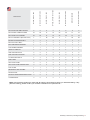
PARTS LIST
DIN 912 M10X25 INBUS SCREW 8 8 8 8 8 8 8 8
DIN 912 M6X12 INBUS SCREW 22 26 14 18 22 26 14 18
DIN 125 M6 FLAT WASHER 22 26 14 18 22 26 14 18
M5 X12 TORX BOLT (External 6-lobe) 4 4 28 28 4 4 28 28
M12X85 ADJUSTABLE FEET 4 4 4 4 4 4 4 4
M12*20 PLASTIC BOLT 4 4 4 4 4 4 4 4
BOTTOM FRAME ASSEMBLY 1 1 1 1 1 1 1 1
TOP FRAME ASSEMBLY 1 1 1 1 1 1 1 1
VERTICAL PROFILE 4 4 4 4 4 4 4 4
SIDE SUPPORT RAILS 2 2 2 2 2 2 2 2
SIDE SUPPORT ADAPTER 0 0 4 4 0 0 4 4
19" MOUNTING RAILS 4 4 4 4 4 4 4 4
SIDE PANEL 2 0 2 0 2 0 2 0
SPLIT SIDE PANEL 0 4 0 4 0 4 0 4
SPLIT SIDE PANEL MIDDLE PART 0 2 0 2 0 2 0 2
TOP COVER 1 1 1 1 1 1 1 1
REAR METAL SOLID PANEL 1 1 1 1 0 0 0 0
FRONT DOOR 1 1 1 1 0 0 0 0
FRONT & REAR PERFORATED DOOR 0 0 0 0 2 2 2 2
LOCK BRACKET 0 0 0 0 1 1 1 1
W=600, D=600 - 800
W=600, D=1000-1070-1200
W=800, D=600 - 800
W=800, D=1000- 1070-1200
W=600, D=600 - 800
W=600, D=1000-1070-1200
W=800, D=600-800
W=800, D=1000-1070-1200
Note: Use the above parts list to check that all parts are accounted for before you start assembling. If any
parts are missing, please contact your reseller or distributor for replacements.

4 l Assembly Instructions | Montageanleitung
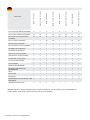
TEILELISTE
Hinweis: Gleichen Sie den Lieferumfang mit dieser Teileliste ab, um die Lieferung auf Vollständigkeit zu
prüfen. Sollten Teile fehlen, wenden Sie sich bitte an Ihren Händler.
DIN 912 M10X25 INBUSSCHRAUBEN
8
8
8
8
8
8
8
8
DIN 912 M6X12 INBUSSCHRAUBEN 22 26 14 18 22 26 14 18
DIN 125 M6 FLACHE UNTERLEG-
SCHEIBEN
22 26 14 18 22 26 14 18
M5 X12 TORX-SCHRAUBEN 4 4 28 28 4 4 28 28
M12X85 NIVELLIERFÜSSE 4 4 4 4 4 4 4 4
M12*20 KUNSTSTOFFSCHRAUBEN 4 4 4 4 4 4 4 4
RAHMEN FÜR UNTERSEITE 1 1 1 1 1 1 1 1
RAHMEN FÜR OBERSEITE 1 1 1 1 1 1 1 1
VERTIKALE TRAGSCHIENEN 4 4 4 4 4 4 4 4
HORIZONTALE TRAGSCHIENEN 2 2 2 2 2 2 2 2
TRAGWINKEL FÜR SEITEN 0 0 4 4 0 0 4 4
19"-MONTAGESCHIENEN 4 4 4 4 4 4 4 4
SEITENWÄNDE 2 0 2 0 2 0 2 0
GETEILTE SEITENWÄNDE 0 4 0 4 0 4 0 4
MITTELTEIL FÜR GETEILTE
SEITENWÄNDE
0 2 0 2 0 2 0 2
DACH 1 1 1 1 1 1 1 1
RÜCKWAND 1 1 1 1 0 0 0 0
FRONTTÜR 1 1 1 1 0 0 0 0
PERFORIERTE TÜR FÜR FRONT-
UND
RÜCKSEITE
0 0 0 0 2 2 2 2
VERRIEGELUNGSPLATTE 0 0 0 0 1 1 1 1
B=600, T=600 - 800
B=600, T=1000-1070-1200
B=800, T=600 - 800
B=800, T=1000- 1070-1200
B=600, T=600 - 800
B=600, T=1000-1070-1200
B=800, T=600-800
B=800, T=1000-1070-1200

Assembly Instructions | Montageanleitung l 5
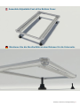
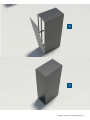
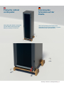
Montieren Sie die Nivellierfüße an dem Rahmen für die Unterseite.
Assemble Adjustable Feet at the Bottom Cover.

6 l Assembly Instructions | Montageanleitung
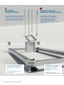
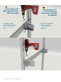
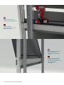
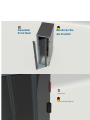
Insert each Vertical as shown.
Fix the Vertical Profiles from both
inner sides by using M10x20
Bolt.
Do not over-tighten. This will
damage the bolt.
Montieren Sie die
vertikalen Tragschienen
Assemble
Vertical Profiles
Montieren Sie die vertikalen
Tragschienen wie abgebildet und
fixieren Sie sie an beiden
Innenseiten mit den M10x20-
Schrauben.
Achten Sie darauf, die
Schrauben nicht zu überdrehen.
Hinweis: Diese Abbildung zeigt die
Montage für einen rechtsseitigen
Türanschlag. Für einen linksseitigen
Türanschlag platzieren Sie die
Tragschiene mit der schwarzen
Türaufhängung entsprechend auf der
anderen Seite.
Note: This image shows the installation
with the door opening from left to right.
If you prefer opening the door from right
to left, you can also place the rail with
the black door fixations on the left side.

Assembly Instructions | Montageanleitung l 7
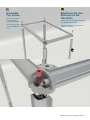
Assemble
Top Frame
Fixieren Sie den Rahmen außen mit
den M10x20-Schrauben.
Achten Sie darauf, die Schrauben
nicht zu überdrehen.
Montieren Sie den
Rahmen für die
Oberseite
Fix the Top Frame
from outside by
using M10x20 Bolt
Do not over-tighten.
This will damage the
bolt.

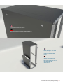
8 l Assembly Instructions | Montageanleitung
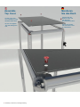
Montieren
Sie das Dach
Fixieren Sie den
Rahmen oben mit
den M12x20-
Kunststoffschrauben.
Achten Sie darauf,
die Schrauben nicht
zu überdrehen.
Assemble
Top Cover
Fix the Top Cover
from outside by using
M12x20 Plastic Bolt
Do not over-tighten.
This will damage the
bolt

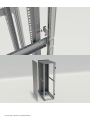
Assembly Instructions | Montageanleitung l 9
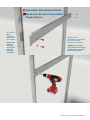
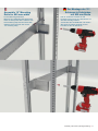
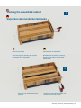
Montieren Sie die horizontalen
Tragschienen
Fixieren Sie die
horizontalen Tragschienen
links und rechts mit
4 x M6 X12-Schrauben
HINWEIS: Horizontale
Tragschienen werden nur
in Schränken mit 26 HE
und höher benötigt.
Assemble Side Support Rails
Fix Left and
Right
Supporting
Rails with 4x
M6 X12 Bolt.
NOTE: Side
support
rails only
required on
cabinets
with 26U
and above.

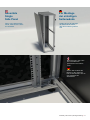
10 l Assembly Instructions | Montageanleitung
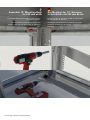
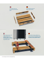
Zur Montage der
19“-Schienen in
Schränken mit 800
mm Breite
Fixieren Sie die Tragwinkel
auf den horizontalen
Tragschienen links und
rechts mit M5 X12 Torx-
Schrauben.
Assembling 19”
Mounting Rails for
800 mm width
Fix Adapters on Side
Support Rails for left and
right side. Each adapter has
to be fixed with M5 X12
Torx.

Assembly Instructions | Montageanleitung l 11
Zur Montage der 19“-
Schienen in Schränken
mit 800 mm Breite
Die 19“-Schienen müssen an drei
Punkten mit fünf X12 Torx-Schrauben am
Schrank befestigt werden.
Verwenden Sie ein Maßband und wählen
Sie einen sinnvollen Abstand von der
Fronttür zu den 19“-Schienen.
Assemble 19” Mounting
Rails for 800 mm width
Fix the Mounting Rails with
M5 X12 Torx. Mounting rails have to be
fixed on three points at the cabinet. Use
the measuring tape and choose a safe
distance (from the front door to the
19” mounting rails).

12 l Assembly Instructions | Montageanleitung
Zur Montage der 19“-Schienen
in Schränken mit 600 mm Breite
Fixieren Sie die 19“-Schienen mit M6 X12-Schrauben
an drei Punkten am Schrank.
Verwenden Sie ein Maßband und wählen Sie einen
sinnvollen Abstand von der Fronttür zu den 19“-
Schienen.
Assemble 19” Mounting Rails
for 600 mm width
Fix the Mounting Rails with M6 X12 Bolt on three
points at the cabinet.
Use the measuring tape and choose a safe
distance (from the front door to the 19” mounting
rails.

Assembly Instructions | Montageanleitung l 13
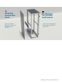
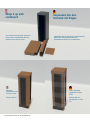
Assemble
Double Side
Panel
Achten Sie vor der Montage
darauf, dass die Schlösser
geöffnet sind.
Zur Montage
der geteilten
Seitenwände
When you install the
Side Panels, make sure
that the locks are
unlocked.

14 l Assembly Instructions | Montageanleitung
Fixieren Sie das
Seitenwandprofil mit einer
M6x12-Schraube.
Setzen Sie zunächst die
Bolzen in die Löcher ein.
Die Löcher befinden sich an
der Unterseite der
Seitenwand.
Screw the Side Panel
Profile by using M6x12 Bolt.
Drive the lugs in the holes
first. The holes are
positioned on the bottom
cover.

Assembly Instructions | Montageanleitung l 15
Schließen Sie die montierten Seitenwände ab.
Lock the mounted side panels.
Setzen Sie zunächst die
Bolzen in die Löcher ein.
Die Löcher befinden sich an
der Unterseite der
Seitenwand.
Drive the lugs in the holes
first. The holes are
positioned on the bottom
cover.

16 l Assembly Instructions | Montageanleitung

Assembly Instructions | Montageanleitung l 17
Assemble
Single
Side Panel
When you install the Side
Panel, make sure the locks
are unlocked.
Zur Montage
der einteiligen
Seitenwände
Achten Sie vor der Montage
der Seitenwände darauf,
dass die Schlösser geöffnet
sind.
Setzen Sie zunächst die
Bolzen in die Löcher ein.
Die Löcher befinden sich an
der Unterseite der
Seitenwand.
Drive the lugs in the holes
first. The holes are
positioned on the bottom
cover.

22 l Assembly Instructions | Montageanleitung
Montieren Sie die
Rückwand/rückseitige Tür
Fixieren Sie die
Verriegelungsplatte der
Rückwand mit M6 X12-
Schrauben.
Assemble
Rear Panel/Door
Fix the Rear Door Lock
Bracket by using M6 X12
Bolt
Drive the lugs in the holes
first. The holes are
positioned on the bottom
cover.
Setzen Sie zunächst die Bolzen in die
Löcher ein. Die Löcher befinden sich an
der Unterseite der Seitenwand.
1

Assembly Instructions | Montageanleitung l 23
18 l Cabinets Installation Manual
2
3

24 l Assembly Instructions | Montageanleitung
Assemble
Front Door
Montieren Sie
die Fronttür
Setzen Sie die Stifte ein.
Insert Pins.
Seite wird geladen ...
Seite wird geladen ...
Seite wird geladen ...
Seite wird geladen ...
Seite wird geladen ...
Seite wird geladen ...
-
 1
1
-
 2
2
-
 3
3
-
 4
4
-
 5
5
-
 6
6
-
 7
7
-
 8
8
-
 9
9
-
 10
10
-
 11
11
-
 12
12
-
 13
13
-
 14
14
-
 15
15
-
 16
16
-
 17
17
-
 18
18
-
 19
19
-
 20
20
-
 21
21
-
 22
22
-
 23
23
-
 24
24
-
 25
25
-
 26
26


in anderen Sprachen
- English: Intellinet 715591
- español: Intellinet 715591
Verwandte Artikel
-
Intellinet 561143 Quick Installation Guide
-
-
Intellinet 561341 Quick Installation Guide
-
-
-
-
Intellinet 509107 Quick Instruction Guide
-