emaux SSC Series Salt Chlorinator Benutzerhandbuch
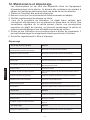
- Kategorie
- Oberirdisches Poolzubehör
- Typ
- Benutzerhandbuch

SSC SERIES
SALT CHLORINATOR
USER MANUAL
SSC25
Deutsch
English Fran aisçNederlands
MESW21090843

1.Working Principle.............................................................
3.Dimension........................................................................
4.Working condition.............................................................
5.Product specification........................................................
6.Product Features...................................................
7.Installation Guide...................................................
Installation............................................................
...............................................
......................................................
2.Product picture.................................................................
8.
9.Operation Overview
10.Control Panel
11.Timer operation (For specific model only)......................
12.Maintenance and troubleshooting..................................
3
3
6
7
8-9
9
10
4
4
4-5
5
6
CONTENT
English
2

3
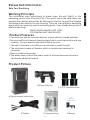
Emaux Salt Chlorinator
Safe Pool Sanitizing
Working Principle
The chlorinator uses electrolysis to break down the salt (NaCl) in the
swimming pool to form Chlorine (Cl2). The control unit of the chlorinator can
regulate the chlorine production by altering the electric current flow through
the titanium electrode in the cell housing. Chlorine is an effective sanitizing
agent which is commonly used in swimming pools, it can inhabit the growth of
bacteria and fungi.
2NaCl+2H2O=2NaOH+H2↑+Cl2↑
Cl2+2NaOH=NaCl+NaClO+H2O
Product Features
ü
ü
ü
ü
ü
ü
Convenience and the constant delivery of pure chlorine-based sanitizer.
No more artificial chemical cleaning agent which could cause skin and eye
irritation. You just need to add natural salt in the pool.
The salt in the water is so little you do not taste or smell the salt.
The electrode is made of titanium, which is durable and resistant to
corrosion.
Easy to install and operate.
The water does not have the heavy smell of chlorine because chlorine is
not directly added to the pool.
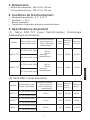
Product Picture
A.Salt chlorinator control box
B.Electrolytic cell C.1.5”/2” universal union
D.Cables E.Screw and fuse F.Manual
SSC25
English

4
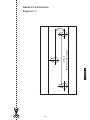
Product Dimension
!
!Electrolytic cell: 380 x 118 x 130 mm
Working Condition
!Environment Temperature: 0 degree Celsius to 50 degree Celsius
!Humdity: ≦ 85%
!Installation Area must be with good ventilation
!Keep away from other heat source
Chlorine Level Calculation
Required Chlorine Production Rate (g/hr) =
Standard Chlorine Level not less than 2mg/litre = 0.002g/litre
Example:
Pool Volume: 65m3 = 65,000litre
Turnover Rate: 4 Hour
Required Chlorine Production Rate (g/hr) = =32.5 g/hr
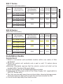
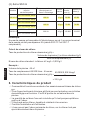
Product Specification:
SSC-TLT Series
(Chlorinator with underwater light, transformer and time switch)
Control Box: 360 x 220 x 135 mm
65,000 litre X 0.002 g/litre
4 Hours
Pool volume (litre) x Standard Chlorine (g/litre)
Turnover Rate (hr)
Salt chlorinator
voltage input/ freq
Rating (salt chlorinator
and underwater
light transformer)
220~250VAC 50/60Hz
100~120VAC 50/60Hz
220~250VAC 50/60Hz
100~120VAC 50/60Hz
100VA
+100VA
(underwater light)
100VA
+160VA
(underwater light)
15g/hr
25g/hr
Model
SSC15-TLT
SSC25-TLT
50000
75000
45000
70000
Fiberglass
Pool (Litre)
Cell
Output
Concrete
Pool
(Litre)
English

5
SSC-T Series
(Chlorinator with time switch)
SSC-E Series
(Basic Salt Chlorinator)
Installation Guide
Control Unit:
1. Select a convenient well-ventilated location within one meter of filter
equipment.
2. Mount the control unit vertically onto a post or wall 1.5 meters above
ground level.
(Australian Standards requires that the electric control unit shall not be
located within 3 meters of the pool water.)
3. Plug Power supply into a suitable weatherproof outlet
4. Plug pump into the power outlet of the Power Supply Unit. (applicable for
SSC-TLT Series only)
5. The Unit must be kept away from acid and other chemical storage areas.
Acid and chemical vapors will corrode the electronics inside the Unit.
6. It must also be kept away from heat sources.
SSC15-E
SSC25-E
220~250VAC 50/60Hz
100~120VAC 50/60Hz
220~250VAC 50/60Hz
100~120VAC 50/60Hz
100VA
160VA
15g/hr
25g/hr
SSC50-E
220~250VAC 50/60Hz
100~120VAC 50/60Hz
300VA 45g/hr
50000 45000
75000 70000
120000 110000
Model Salt chlorinator
voltage input/ freq
Cell
Output
Fiberglass
Pool (Litre)
Concrete
Pool(Litre)
Rating (salt chlorinator
and underwater
light transformer)
SSC15-T
SSC25-T
220~250VAC 50/60Hz
100~120VAC 50/60Hz
220~250VAC 50/60Hz
100~120VAC 50/60Hz
100VA
160VA
15g/hr
25g/hr
SSC50-T
220~250VAC 50/60Hz
100~120VAC 50/60Hz
300VA 45g/hr
50000 45000
75000 70000
120000 110000
Model Salt chlorinator
voltage input/ freq
Cell
Output
Fiberglass
Pool (Litre)
Concrete
Pool(Litre)
Rating (salt chlorinator
and underwater
light transformer)
English

Caution:
! The control unit can connect to one pump and one underwater light only (SSC-TLT
Series Only)
! The current loading of the pumped connected must not exceed 8 Amp. (SSC-TLT
Series Only)
Electrolytic cell and Electrode
1. The cell must be installed horizontally
2. Connect the water inlet and outlet to the Cell Unit. The water flow direction
must be as indicated on the Cell.
3. To avoid lost of chlorine, the Cell should be installed at the end of the
filtration system, right before the pool water return.
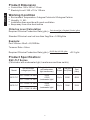
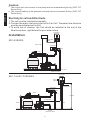
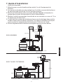
Installation
SSC-E SERIES
SSC-T & SSC-TLTSERIES
6
Waste
Filter Pump Suction
(Water from Pool)
Return to Pool
Pump
Return
Pump Cable
Cell Cable
Cell
Power
Supply
Control Box
Pool Light
Cable (if fitted)
1.5meter
Pole
Power Supply
Control Box
Pump Cable
Control Box
Cable
Cell Cable
Pump
Return
Filter Pump Suction
(Water from Pool)
Return to Pool
Cell
English

7
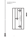
1. Two self-tapping screws and wall plugs have been provided for fast and
simple installation. Simply cut out Template provided for the location of
drill entry points. Use a 8mm masonry drill when fitting control unit to a
brick or concrete wall. When mounting to a post drill pilot holes and fit
screws provided. Once screws are in position simply hang the chlorinator
via the bracket on back of Control Box.
2. Glue the salt cell horizontally on the pool return pipe, allow 24 hour curing
of the pipe glue.
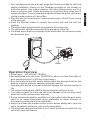
3. Used the provided cable to connect the control unit and the salt cell
together,
IThe single black plug should be connected to the control unit.
IThe yellow wire shall be connected to the gas senor of the Cell
IThe black wires shall be connected to the electrodes; the connectors may
be fitted either way.
Operation Overview
1. Power input: 220-240VAC, 50/60Hz
2. Recommended pool salt lever: 4000PPM or above (no less than 40kg of
pure salt dissolved in 10,000 liter of pool water)
=Run chlorinator at the Salt Levels stated within this document and on the
product to ensure optimum sanitizer output and cell life.
=Operating this device at low salt levels will damage the cell and reduce its
life.
=The control unit displays a RED indicator when the salt level is low.
=If no action is taken to rectify the salt level, damage to the cell may result
which will not be covered under warranty.
3. During extreme hot weather conditions or high bather load, the pool water
need to be super-chlorinated using granulated or liquid chlorine or
increase the running time of the chlorinator.
4. Always turn down the system control to zero before adding salt, once the
salt is completely dissolved, return to the set position.
5. The aluminum casing at the back of the Control Unit acts as a heat sink, do
not touch it with bare hands.
Black
Yellow
Black
English

OFF
ON
ON
SYSTEM-CONTROL
MIN MAX
FUSE-250 V
F2.5 A
OPERATION
1
2
STAND-BY NO FLOW
WINTER
SWITCH
+
-
CELL
OFF
AUTO
FUSE-250 V
LIGHT
OFF
LIGHT
ON
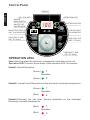
Control Panel
OPERATION LEDs
Fuse:Used to protect the electronic components inside the control unit.
Operation LED:There are three status of the operation LED, for example
Status1:Normal Operation
Status2: Low salt level/ Deposition on the electrode/ Low water temperature
Status3:Extremely low salt level/ Serious deposition on the electrode/
Extremely low water temperature
8
OPERATION LEDs
FUSE FOR SALT
CHLORINATOR
FUSE FOR LIGHT
(SSC-TLT ONLY)
TIMER
SSC-TLT ONLY)
(SSC-T AND
CELL POLARITY
WINTER
MODE SWITCH
ON/OFF FOR
WINTER MODE
LIGHT(SSC-T AND
SSC-TLT ONLY)
1
2
Operation
1
2
Operation
1
2
Operation
DISPLAY
ON/OFF BUTTON FOR
SALT CHLORINATOR
SYSTEM CONTROL
(Green)
(Green)
(Green)
(Red)
(Red)
(Red)
English

9
SALT CHLORINATOR On/Off/Auto: ON/Off Switch. In Auto mode, the
chlorinate is operated by the timer setting
Light On/Off: Switch for underwater light connected to the control unit (For
certain model)
System Control: Adjust the chlorine product of the chlorinator, for example,
for the control unit turned on for 8 hours
Set at 100% - The salt cell operated at 8 hours
Set at 50% - The salt cell operated at 4 hours
Set at 25% - The salt cell operated at 2 hours
Display: Show the percentage of the chlorine production
Winter Mode Switch and On/ Off LED: Turn on to change the chlorine
production at 85% .
Cell Polarity LED: Show the polarity of the electrodes; the polarity of the
electrode will shifted every 8 hrs of operation, so as to clean the deposition
on the electrode.
Timer: Used to set the program to turn on and off the control unit
automatically. (SSC-T AND SSC-TLT ONLY)
Stand-By LED: Turn on when chlorinate is in stand-by mode, When the
chlorinator is turn on, the standby LED will go off after 35 sec.
No Flow LED: Turn on if there is no water flow, if there is no water flow, the
pump and salt chlorinator will stop automatically.
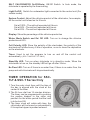
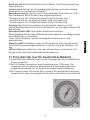
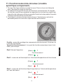
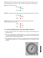
TIMER OPERATION for SSC-
TLT & SSC-T Series Only
1.Turn the outer clock face until the time of
the day is aligned with the clock at the
center of the timer
2.The 24-hour dial has 15 minutes division.
The timer can be programmed by pushing
the captive trippers to the outer ring
position for the entire period that the load
is to be turn ON.
3.The timer clock will rotate with time; the
chlorinator will be turned on automatically
if its captive tripper is pushed outward.
English

10
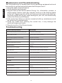
Maintenance and Troubleshooting
Troubleshooting
Salt Chlorinators are a valuable piece of pool sanitizing equipment and must
be cared for to get the best performance and life span from it.
1. Keep the water chemical balance
2. Good operation environment
3. Regular check of the titanium plates.During the chlorination process a
white powder Calcium scale may naturally build up on the titanium plates
in the cell. Regular monitor of the cell to prevent excessive scale build up.
Excessive scale build up will cause damage to your cell, and dramatically
reduce its efficiency and lifespan.
4.If the control box failure or calcium excessive build up, maintenance must
be carried out by professionals.
5. Avoid any incest from entering the control box, it may damage the
electrical component inside.
6. Regular monitor of the filter and pump
1. Low/no chlorine production How to handle
- Check the electrical plug/control box/ pump power - Connect the power properly
- Setting system is too low - Turn the system control to maximum
- Automatically stopped by the timer setting - Adjust the timer setting
- Blown fuse - Cut the power and replace the fuse
- excessive scale build up on the cell
- Switch off the salt chlorinator and clean the salt cell by professional
serviceman.
- Filter Backwashing - Once the backwash is complete, turn the filter back to normal
filtration
- The gas sensor is not connected - Connect the gas senor according to this manual
- Pump malfunction - Stop the filtration system and repair the pump
- Water temperature too low - Turn on the winter switch
- Salt lever too low - Add salt to the pool
- pH valve too high - Check the water pH valve and keep it around 7.0-7.6
2. No flow
- Pump malfunction - Stop the filtration system and repair the pump
- Filter Backwashing - Once the backwash is complete, turn the filter back to normal
filtration
- The gas sensor is not connected - Connect the gas senor according to this manual
3. No display
- Setting system is too low - Turn the system control to maximum
English

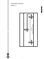
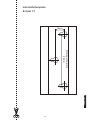
Installation template
Ratio 1:1
90mm
Mounting Template
16mm
English
11

SSC SERIE
SALZCHLORINATOR
BENUTZERHANDBUCH
SSC25
Deutsch

1.Arbeitsprinzip....................................................................
3.Abmessung.......................................................................
4.Arbeitszustand.............................................
5.Produktspezifikation...............................
6.Produkteigenschaften
7.Installationsanleitung
Installation
2.Produktbild.......................................................................
.....................
...........................
.......................................................
........................................................
8. ........................................................................
9.Bedienungsüberblick.........................................................
10.Steuertafel.......................................................................
11.Timerbetrieb (nur für spezielles Modell)...........................
12.Wartung und Problemlösung............................................
3
3
6
7
8-9
9
10
4
4
4-5
5
6
INHALTSVERZEICHNIS
2
Deutsch

3
SALZCHLORINATOR
Sichere und zuverlässige Poolreinigung
1.Arbeitsprinzip
Der Chlorinatorbricht durch Elektrolysedas Salz (NaCl) auf, das dem
Swimmingpool beigegeben wurde und bildet daraus Chlor (Cl2). Die
Steuereinheit des Chlorinators kann die Chlorproduktion durch Anpassung
des Stromflusses durch die Titanelektrodedes Zellengehäuses steuern.
Natriumhypochlorid bildet sich aus Chlor. Es ist ein wirkungsvolles
Reinigungsmittel, das häufig in Swimmingpools eingesetzt wird. Es kann das
Wachstum von Bakterien und Pilzen verhindern.
2NaCl+2H2O=2NaOH+H2↑+Cl2↑
Cl2+2NaOH=NaCl+NaClO+H2O
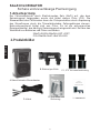
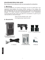
2.Produktbilder
A.Salzchlorinator-Steuerkasten
B.Elektrolyse-Zelle
C.1,5”/2” Universalverbindung
D. Kabel E. Schraube und
Sicherung F. Handbuch
SSC25
Deutsch

4
3. Abmessungen
!
!Elektrolyse-Zelle: 380 x 118 x 130 mm
4. Arbeitszustand
! Umgebungstemperatur: 0°C-50°C
! Feuchtigkeit: ≦ 85%
! Gute Belüftung
! Von anderer Wärmequelle entfernt halten
!
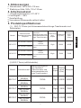
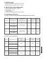
5. Produktspezifikationen
(1) SSC-TLT-Serie (mit Unterwasserbeleuchtungs-Transformator und
Zeitschalter)
Steuerkasten: 360 x 220 x 135 mm
Modell
Salzchlorinator
Spannungseingang/
Frequenz
Nennwert
(Salzchlorinator und
Unterwasserbeleucht
ungs-Transformator)
Zellenausg
ang
Output
Glasfaserp
ool (Liter)
Betonpool
(Liter)
Pool
(Liter)
SSC15-TLT
220-250VAC 50/60Hz
100VA
+100VA
(Unterwasserbeleuch
tung)
15g/h
50000
45000
100-120VAC 50/60Hz
SSC25-TLT
220-250VAC 50/60Hz
100VA
+160VA
(Unterwasserbeleuch
tung)
25g/h
75000
70000
100-120VAC 50/60Hz
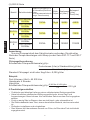
(2).SSC-T Serie (mitZeitschalter)
Modell
Salzchlorinator
Spannungseingang/F
requ.Nennwert
(Salzchlorinator und
Unterwasserbeleucht
ungs-Transformator)
Zelle
Output
Glasfas
erpool
(Liter)
Betonpoo
SSC15-T
220-250VAC
50/60Hz
100VA
15g/h
50000
45000
100-120VAC
50/60Hz
SSC25-T
220-250VAC
50/60Hz
160VA
25g/h
75000
70000
100-120VAC
50/60Hz
SSC50-T
220-250VAC
50/60Hz
300VA
45g/h
120000
110000
100-120VAC
50/60Hz
Deutsch

5
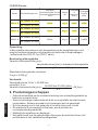
(3).SSC-E Serie
Modell
Salzchlorinator
Spannungseingang/Fre
qu.Nennwert(Salzchlori
nator
undUnterwasserbeleuch
tungs-Transformator)
Zelle
Output
Glasfaserp
ool (Liter)
Betonpool
(Liter)
Pool(Liter)
SSC15-
E
220~250VAC
50/60Hz
100VA
15g/h
50000
45000
100~120VAC
50/60Hz
SSC25-
E
220~250VAC
50/60Hz
160VA
25g/h
75000
70000
100~120VAC
50/60Hz
SSC50-
E
220~250VAC
50/60Hz
300VA
45g/h
120000
110000
100~120VAC
50/60Hz
Anmerkung:
Nur eine Pumpewird mit dem Salzchlorinator verbunden. Die aktuellen
Werte der Pumpe übersteigen nicht 8Amp (nur bei Serie SSC-TLT und SSC-T
Serie)
Chlorpegelberechnung
Erforderliche Chlorproduktionsrate (g/h)=
Standard-Chlorpegel: nicht unter 2mg/Liter = 0,002 g/Liter
Poolvolumen (Liter) x Standardchlor (g/Liter)
Umsatzrate (hr)
Beispiel:
Pool-Volumen: 65m3 = 65.000 Liter
Umsatzrate: 4 Stunden
Literg/Liter
Erforderliche Chlorproduktionsrate (g/h)=
65,000 litre X 0.002 g/litre
4 h
=32.5 g/h
6.Produkteigenschaften
√ Praktische und ständige Lieferung reinen chlorbasierten Reinigungsmittels
√ Keine künstlichen chemischen Reinigungsmittel mehr, die zu Haut- und
Augenreizungen führen können. Nur natürliches Salz muss dem Pool zugegeben
werden.
√ Es ist so wenig Salz im Wasser, dass es nicht riech- oder schmeckbar ist.
√ Die Elektrodebesteht aus Titan, einem dauerhaften Material, das korrosionsfest
ist.
√ Einfach zu installieren und zu betreiben.
√ Dem Wasser fehlt der schwere Geruch von Chlor, da Chlor dem Pool nicht direkt
zugegeben wird.
Deutsch

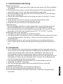
7.Installationsanleitung
Steuergerät
1.Wählen Sie einen geeigneten, gut belüfteten Ort innerhalb eines Meters um das
Filtergerät herum.
2.Australische Standards verlangen, dass das elektrischeSteuergerätmehr als
drei (3) Meter vom Poolwasser entfernt ist.
3.Stecken Sie die Stromversorgung in eine geeignete wasserfeste Steckdose und
stecken Sie die Pumpe in die Steckdose des Netzgeräts.
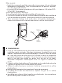
4. Steuergerät vertikal auf einem Pfosten oder einer Wand 1,5Meter über dem
Boden montieren.
5.Die Einheit muss entfernt von Säure und anderen Lagerbereichen für
Chemikalien gelagert werden. Säure- und chemische Dämpfe korrodieren die
Elektronik in dem Gerät.
6.Es ist auch von Wärmequellen fernzuhalten.
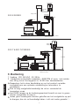
Installation
SSC-E SERIES
SSC-T & SSC-TLTSERIES
6
Waste
Filter Pump Suction
(Water from Pool)
Return to Pool
Pump
Return
Pump Cable
Cell Cable
Cell
Power
Supply
Control Box
Pool Light
Cable (if fitted)
1.5meter
Pole
Power Supply
Control Box
Pump Cable
Control Box
Cable
Cell Cable
Pump
Return
Filter Pump Suction
(Water from Pool)
Return to Pool
Cell
Deutsch

7
Vorsicht:
--Das Steuergerät kann sich mit nur einer Pumpe und einer
Unterwasserbeleuchtung verbinden. Siehe vorherige Seite für
Produktspezifikationen
--Die aktuelle Last der angeschlossenen Pumpen darf 8 Ampnicht
überschreiten(gilt nur für Serie SSC-TLT und SSC-T).
Elektrolyse-Zelle und Elektrode
1.Die Elektrolyse-Zellemuss horizontal installiert werden.
2.Um Verlust von Chlor zu vermeiden, sollte die Elektrolyse-Zelleam Ende
des Filtersystems direkt vor dem Poolwasserrücklauf installiert werden.
3.Um den Wasserein- und -auslass an die Elektrolyse-
Zelleanzuschließen,beachten Sie die Wasserflussrichtung, die an der
Elektrolyse-Zelle angegeben ist.
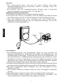
Black
Yellow
Black
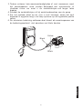
8.Installation
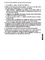
1.Drei Madenschrauben und Wandstecker liegen für eine schnelle und
einfache Installation bei. Schneiden Sie einfach die Schablone aus, um
die Bohrstellen festzulegen. Verwenden Sie einen 8-mm-Steinbohrer, um
die Schraublöcher in dieBetonwand entsprechend der Positionin in der
Schablone zu bohren. Befestigen Sie die drei Madenschrauben in dem
gebohrten Loch. Wenn sich die Schrauben in Position befinden, hängen
Sie den Chlorinatoreinfach an die Klammer hinten am Gerät.
2.Kleben Sie die Elektrolyse-Zelle horizontal auf das Rücklaufrohr des Pools
und lassen Sie die Klebeverbindung am Rohr 24 Stunden lang aushärten.
3.Mit dem beiliegenden Kabel verbinden Sie das Steuergerät mit der
Elektrolyse-Zelle.
ø Der einzelne schwarze Stecker sollte mit dem Steuergerät verbunden
werden.
ø Das gelbe Kabel wird mit dem Gas-Sensor derselben Zelle verbunden.
ø Die schwarzen Kabel werden mit den Elektroden verbunden. Die
Anschlüsse können in jeder Richtung angebracht werden.
Deutsch

9.Betriebsüberblick
1. Stromversorgung: 220-240VAC, 50/60Hz
2.Empfohlener Salzpegel im Pool: 4000PPM oder mehr (nicht unter
40kg reines Salz pro 10.000 Liter Poolwasser)
▶ Lassen Sie den hlorinatorit den Salzpegeln laufen, die in diesem
Dokument und auf dem Produkt vorgegebensind um ine este
Reinigungswirkung und lgste Zellenstandzeit zu gewrleisten
▶ Betrieb des Gers mit gringen Salzpegeln beschigt die Zelleund
verringert die Standzeit
▶ Das teuergereigt eine ROTE Lampe, wenn die Salzpegel zu tief
sind
▶ Wenn nichts unternommen ird um die Salzpegel zu korrigieren,
kann es zu Schen an der Zelle kommen, der nicht vonder Garantie
abgedeckt wird
3. Bei extrem heim Wetter oder hohem Badeaufkommen muss das
Polasser superchloriniert werden. Dazu wird Chlorgranulat oder
flsiges Chlor verwendet oder die Laufzeit des hlorinator erht
4. Der alzchlorinatoruss usgeschaltet werden, wenn die Pumpe arbeitet.
5. Drehen Sie die Systemsteuerung auf null, bevor Sie Salz zugeben.
Wenn das Salz ganz gelt ist, stellen Sie die Sollposition wieder her
6. Das Aluminiumgehse hinten dient als Klkper des Steuergers. erren
Sie es nicht mit der blon Hand
Deutsch
8

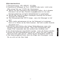
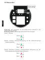
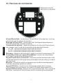
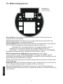
10.Steuertafel
Sicherung: wird verwendet, um die elektronischen Bauteile in der
Steuereinheit zu schützen.
Bedienungs-LED:die Bedienungs-LED hat drei Statusanzeigen.
Status 1: Normaal
Status2: Geringer Salzpegel/Ablagerung auf der Elektrode/geringe
Wassertemperatur
Status3: Besonders geringer Salzpegel/starke Ablagerung auf der
Elektrode/besonders geringe Wassertemperatur
1
2
Betrieb
1
2
Betrieb
1
2
Betrieb
(Green)
(Green)
(Green)
(Red)
(Red)
(Red)
Deutsch
Siehe folgende
Beschreibung
9
Seite wird geladen ...
Seite wird geladen ...
Seite wird geladen ...
Seite wird geladen ...
Seite wird geladen ...
Seite wird geladen ...
Seite wird geladen ...
Seite wird geladen ...
Seite wird geladen ...
Seite wird geladen ...
Seite wird geladen ...
Seite wird geladen ...
Seite wird geladen ...
Seite wird geladen ...
Seite wird geladen ...
Seite wird geladen ...
Seite wird geladen ...
Seite wird geladen ...
Seite wird geladen ...
Seite wird geladen ...
Seite wird geladen ...
Seite wird geladen ...
Seite wird geladen ...
Seite wird geladen ...
Seite wird geladen ...
Seite wird geladen ...
Seite wird geladen ...
-
 1
1
-
 2
2
-
 3
3
-
 4
4
-
 5
5
-
 6
6
-
 7
7
-
 8
8
-
 9
9
-
 10
10
-
 11
11
-
 12
12
-
 13
13
-
 14
14
-
 15
15
-
 16
16
-
 17
17
-
 18
18
-
 19
19
-
 20
20
-
 21
21
-
 22
22
-
 23
23
-
 24
24
-
 25
25
-
 26
26
-
 27
27
-
 28
28
-
 29
29
-
 30
30
-
 31
31
-
 32
32
-
 33
33
-
 34
34
-
 35
35
-
 36
36
-
 37
37
-
 38
38
-
 39
39
-
 40
40
-
 41
41
-
 42
42
-
 43
43
-
 44
44
-
 45
45
-
 46
46
-
 47
47


emaux SSC Series Salt Chlorinator Benutzerhandbuch
- Kategorie
- Oberirdisches Poolzubehör
- Typ
- Benutzerhandbuch
in anderen Sprachen
Andere Dokumente
-
Bestway FLOW Clear Bedienungsanleitung
-
Waterco Electrochlor Chlorinators Benutzerhandbuch
-
Pool Technologie Poolsquad Benutzerhandbuch
-
Astralpool CTX Series Bedienungsanleitung
-
LifeStraw Peak Series Benutzerhandbuch
-
Bestway Chlorinator Bedienungsanleitung
-
Zodiac WW000031 Benutzerhandbuch
-
 swim fun Easy Salt Chlorine Generator 30 m3 Benutzerhandbuch
-
 Davey Water Products EcoSalt DES13CE Bedienungsanleitung
-
 ZELIA ZLT50 Technical Instructions


