SICK SENSICK WL 260 Bedienungsanleitung
- Kategorie
- Spielzeuge
- Typ
- Bedienungsanleitung

ENGLISH
Photoelectric Reflex Switch
with polarisation filter
Operating Instructions
Safety Specifications
‡ Read the operating instructions before starting operation.
‡ Connection, assembly, and settings only by competent
technicians.
‡ Protect the device against moisture and soiling when operating.
‡ No safety component in accordance with EU machine guidelines.
Proper Use
The WL 260 photoelectric reflex switch is an optoelectronic sensor
and is used for detection of optical, non-contanct detection of
objects, animals, and people. A reflector is required for operation.
Starting Operation
1 Open cover and guard of photoelectric switch; ensure that no
dirt enters device.
2 L.ON: Light-switching; if light received, output (Q) switches.
D.ON: dark-switching, if light interrupted, output (Q) switches.
WL 260-F onlWL 260-F onl
WL 260-F onlWL 260-F onl
WL 260-F onl
y:y:
y:y:
y: PNP positive-switching,
WL 260-E onlWL 260-E onl
WL 260-E onlWL 260-E onl
WL 260-E onl
y:y:
y:y:
y: NPN=negative-switching.
WL 260-R and -S onlWL 260-R and -S onl
WL 260-R and -S onlWL 260-R and -S onl
WL 260-R and -S onl
y:y:
y:y:
y: Light-switching.
Relay 1x u, separated galvanically.
3
With fWith f
With fWith f
With f
olloollo
olloollo
ollo
wing connectorwing connector
wing connectorwing connector
wing connector
s onls onl
s onls onl
s onl
y:y:
y:y:
y:
Connect and secure cable receptacle tension-free.
OnlOnl
OnlOnl
Onl
y in vy in v
y in vy in v
y in v
erer
erer
er
sions with tersions with ter
sions with tersions with ter
sions with ter
minal clamp area:minal clamp area:
minal clamp area:minal clamp area:
minal clamp area:
Loosen 1/2" PF screwed connection, remove sealing plugs.
Cable outlets downward or to the back. Pass the dead power
supply line through and connect the sensor according to
connection diagram B.
Close protective cover.
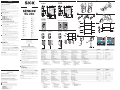
4 Mount suitable reflector opposite photoelectric switch and
align roughly. Adjust for scanning range (see technical data at
end of these operating instructions and see diagram;
x=scanning range, y=operating reserve).
Connect photoelectric switch to operating voltage (see type
label).
Aligning light reception:
Turn the knob >SENS.< to max.
Determine the on/off switching point of the LED signal
strength indicator by horizontal and vertical swinging of the
photoelectric switch. Select the middle setting, so that the red
sender light beam hits the reflector middle. When the light
reception is optimal, the switching output switches into the
state set in 2. If no or too little light is received: Realign and/or
clean the photoelectric switch and reflector.
5 Checking object detection:
Place the object in the beam; the switching output switches.
Reduce the sensitivity on the rotary knob >SENS.< when
there are small or transparent objects. After you remove the
object, the switching output must switch again. If this is not the
case, readjust the sensitivity and check the application
conditions.
Check sealing faces, seals, and screwed joints, then replace and
screw down cover.
6 Options:
WL 260-R270 onlWL 260-R270 onl
WL 260-R270 onlWL 260-R270 onl
WL 260-R270 onl
y:y:
y:y:
y:
Select time delays (ON.DLY=switch-on delay;
OFF.DLY=switch-off delay).
After setting the time delay, make fine adjustments at the
respective control knobs. The possible settings range from 0.1
to 10 sec.
The WL 260-E and -F only devices have a
test input (TE)test input (TE)
test input (TE)test input (TE)
test input (TE),
with which proper functioning of the device can be checked.
When the light path is clear between the photoelectric switch
and the reflector (the LED signal strength control is lit), activate
the test input (see the B connection diagram). This switches off
the transmitter. At the same time, the LED signal strength
control must switch off, and the switching state at the output
must change.
Maintenance
SICK photoelectric switches do not require any maintenance. We
recommend that you clean the optical interfaces and check the
screw connections and plug-in connections at regular intervals.
DEUTSCH
Reflexions-Lichtschranke
mit Polarisationsfilter
Betriebsanleitung
Sicherheitshinweise
‡ Vor der Inbetriebnahme die Betriebsanleitung lesen.
‡ Anschluß, Montage und Einstellung nur durch Fachpersonal.
‡ Gerät bei Inbetriebnahme vor Feuchte und Verunreinigung
schützen.
‡ Kein Sicherheitsbauteil gemäß EU-Maschinenrichtlinie.
Bestimmungsgemäße Verwendung
Die Reflexions-Lichtschranke WL 260 ist ein opto-elektronischer
Sensor und wird zum optischen, berührungslosen Erfassen von
Sachen, Tieren und Personen eingesetzt. Zum Betrieb ist ein
Reflektor erforderlich.
Inbetriebnahme
1 Deckel und Schutzhaube der Lichtschranke öffnen; darauf
achten, daß kein Schmutz in das Gerät gelangt.
2 L.ON: hellschaltend, bei Lichtempfang schaltet Ausgang (Q).
D.ON: dunkelschaltend, bei Lichtunterbrechung schaltet
Ausgang (Q).
Nur Nur
Nur Nur
Nur
WL 260-F:WL 260-F:
WL 260-F:WL 260-F:
WL 260-F: PNP=plusschaltend,
Nur Nur
Nur Nur
Nur
WL 260-E:WL 260-E:
WL 260-E:WL 260-E:
WL 260-E: NPN=minusschaltend.
Nur Nur
Nur Nur
Nur
WL 260-R und -S:WL 260-R und -S:
WL 260-R und -S:WL 260-R und -S:
WL 260-R und -S: Hellschaltend.
Relais 1x u, galvanisch getrennt.
3
Nur bei den SteckNur bei den Steck
Nur bei den SteckNur bei den Steck
Nur bei den Steck
erer
erer
er
vv
vv
v
erer
erer
er
sionen:sionen:
sionen:sionen:
sionen:
Leitungsdose spannungsfrei aufstecken und festschrauben.
A 1 4
Nur bei Nur bei
Nur bei Nur bei
Nur bei
VV
VV
V
erer
erer
er
sionen mit Klemmenanschlußrsionen mit Klemmenanschlußr
sionen mit Klemmenanschlußrsionen mit Klemmenanschlußr
sionen mit Klemmenanschlußr
aum:aum:
aum:aum:
aum:
1/2"-PF-Verschraubung lösen, Dichtungsstopfen entfernen.
Leitungsaustritt nach unten oder hinten. Spannungsfreie
Versorgungsleitung durchführen und Sensor nach Anschluß-
schema B anschließen.
Schutzklappe schließen.
4 Geeigneten Reflektor gegenüber der Lichtschranke montieren
und grob ausrichten. Dabei Reichweite beachten (s. technische
Daten am Ende dieser Betriebsanleitung und s. Diagramm;
x=Reichweite, y=Funktionsreserve).
Sensor an Betriebsspannung legen (s. Typenaufdruck); Justage
Lichtempfang:
Drehknopf >SENS.< auf Max. stellen.
Ein-Ausschaltpunkte der Empfangsanzeige durch horizontales
und vertikales Schwenken der Lichtschranke ermitteln.
Mittelstellung so wählen, daß der rote Sendelichtstrahl in der
Reflektormitte auftrifft. Bei optimalem Lichtempfang wechselt
der Schaltausgang in den in 2 eingestellten Zustand. Wird kein
oder zuwenig Licht empfangen: Lichtschranke und Reflektor
neu justieren bzw. reinigen.
5 Kontrolle Objekterfassung:
Objekt in den Strahlengang bringen; Schaltausgang wechselt. Bei
kleinen oder transparenten Objekten die Empfindlichkeit am
Drehknopf >SENS.< reduzieren. Nach Entfernen des Objektes
muß der Schaltausgang wieder wechseln. Ist dies nicht der Fall,
Empfindlichkeit weiter anpassen, Einsatzbedingungen überprü-
fen.
Dichtflächen, Dichtungen und Verschraubungen kontrollieren,
dann Deckel aufsetzen und festschrauben.
6 Optionen
Nur Nur
Nur Nur
Nur
WL 260-R 270:WL 260-R 270:
WL 260-R 270:WL 260-R 270:
WL 260-R 270:
Zeitstufen (ON.DLY=Einschaltverzögerung, OFF.DLY=
Ausschaltverzögerung) vorwählen.
Nach Zeitstufenvorwahl die Feineinstellung am jeweilgen
Drehknopf vornehmen; Einstellmöglichkeit von 0,1 bis 10 sec.
Die Geräte WL 260-E und -F verfügen über einen
TT
TT
T
esteingangesteingang
esteingangesteingang
esteingang
(TE)(TE)
(TE)(TE)
(TE), mit dem die ordnungsgemäße Funktion der Geräte
überprüft werden kann. Bei freiem Lichtweg zwischen
Lichtschranke und Reflektor (Empfangsanzeige leuchtet) den
Testeingang aktivieren (s. Anschlußschema B); dadurch wird der
Sender abgeschaltet. Gleichzeitig muß die Empfangsanzeige
erlöschen, und der Schaltzustand am Ausgang muß sich ändern.
Wartung
SICK-Lichtschranken sind wartungsfrei. Wir empfehlen, in regelmäßi-
gen Abständen
- die optischen Grenzflächen zu reinigen,
- Verschraubungen und Steckverbindungen zu überprüfen.
B
2 5
6
3
We reserve the right to make changes without prior notification
Änderungen vorbehalten
Sous réserve de modifications
Reservam-se alteraç ões
Ret til ændringer forbeholdes
Con riserva di modifiche
Wijzigingen voorbehouden
Reservado el derecho a introducir modificaciones
0999 HJS
WL 260
WL 260-F270
WL 260-E270
WL 260-S270
WL 260-R270
WL 260-F470
WL 260-E470
WL 260-R270WL 260-S270
WL 260-F270
WL 260-F470
WL 260-E270
WL 260-E470
WL 260-F270
WL 260-E270
WL 260-F470
WL 260-E470
WL 260-S270
WL 260-R270
WL 260-R270
t=0,1–10 s
SICK AG
Schiess-Straße 56
D-40549 Düsseldorf
(02 11) 53 01-0
Fax: (02 11) 53 01-100
www.sick.de.
Australia
Erwin Sick Optic-Electronic Pty. Ltd.
Ivanhoe
(03) 94 97 41 00
Austria
SICK GmbH
2355 Wiener Neudorf
(0 22 36) 622 88-0
Belgium/Luxembourg
Sick Optic-Electronic N.V./S. A.
Asse (Relegem)
(02) 4 66 55 66
Brazil
Sick Indústria & Comércio Ltda.
São Paulo
(11) 55 61 26 83
China/Hong Kong
Sick Optic-Electronic Co., Ltd.
Kowloon
(20) 27 63 69 66
Denmark
SICK A/S
Birkerød
45 82 64 00
Finland
Sick Optic-Electronic Oy
Helsinki
(09) 72 88 500
France
Sick Optique-Electronique
Marne la Valée
(01) 64 62 35 00
Great Britain
Erwin Sick Ltd.
St. Albans
(0 17 27) 83 11 21
Italy
SICK Optic-Electronic S.p.A.
Cernusco sul Naviglio -MI-
(02) 92 14 20 62
Japan
Sick Optic-Electronic K.K.
Tokyo
(03) 33 58-13 41
Netherlands
Sick B. V.
AD Bilthoven
(0 30) 2 29 25 44
Norway
SICK AS
Gjettum
(67) 56 75 00
Poland
Sick Optic-Electronic Sp. z. o. o.
Warszawa
(22) 644-83 45
(22) 644-47 24
Singapore
SICK Optic-Electronic Pte. Ltd.
Singapore 387 383
(65) 744 37 32
Spain
Sick Optic-Electronic S. A.
Sant Just Desvern
(93) 480.31.00
Sweden
SICK AB
Vårby
(08) 680 64 50
Switzerland
Sick AG
Stans
(41) 61 92 93 9
Taiwan
SICK Optic-Electronic Co., Ltd.
Taipei
(02) 23 65-62 92
USA
SICK Optic-Electronic Inc.
Bloomington, MN 55438
(612) 9 41-67 80
Seite wird geladen ...
-
 1
1
-
 2
2


SICK SENSICK WL 260 Bedienungsanleitung
- Kategorie
- Spielzeuge
- Typ
- Bedienungsanleitung
in anderen Sprachen
- English: SICK SENSICK WL 260 Operating instructions
- français: SICK SENSICK WL 260 Mode d'emploi
- español: SICK SENSICK WL 260 Instrucciones de operación
- italiano: SICK SENSICK WL 260 Istruzioni per l'uso
- Nederlands: SICK SENSICK WL 260 Handleiding
- português: SICK SENSICK WL 260 Instruções de operação
- dansk: SICK SENSICK WL 260 Betjeningsvejledning
Verwandte Artikel
-
SICK SENSICK WL36-V Bedienungsanleitung
-
-
-
-
-
-
-
-
-