YOSE POWER TSDZ2 Installationsanleitung
- Kategorie
- Wand
- Typ
- Installationsanleitung

TSDZ2 Central Motor Drive System
Installation manual

Appreciate for purchasing YOSE POWER electric bicycle Kits
01
10
Please turn to page 2 to obtain the user manual in English.
Vielen Dank für den Kauf des Yongsheng Elektrofahrrad-Kits
Um das deutsche Handbuch zu lesen, gehen Sie bitte auf Seite 6
19
Merci d'avoir acheté les e-bike kits de YOSE POWER
Pour lire le manuel en français, veuillez vous rendre à la page 10

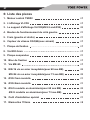
Motor Installation Process 2
Display Installation Process 5
Detection vehicle speed sensor Installation 6
System connection 7
The wiring diagram 7
Motor mounting dimensions 8
Parts List 9
01

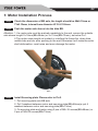
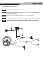
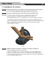
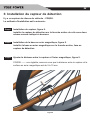
1: Motor Installation Process
Check the dimension of BB axle, the length should be 68±0.15mm or
73±0.15mm, internal bore diameter Ø 33.6-33.8mm.
Install Securing plate. Please refer to Pic2.
Push the motor axle sleeve into the bike BB.
Attention: 1. the motor axle must be pushed completely to the end, ensure the outside
axle sleeve lenght X=16mm(BB=68mm) or X=11mm(BB=73mm), as below Pic1.
2.The motor case should not contact or interfere the frame fox, down tube,
middle tube and etc. after pushing to the end. Otherwise it will make the motor
shell deformation, creat noise and even damage the motor.
1. Put securing plate onto BB axle.
2. Put 2 washers between motor and securing plate(BB=68mm)or put 4
washers between motor and securing plate(BB=73mm)
3. Fix securing plate and motor using 2 pcs of M5×16 screws(BB=68mm) or
2 pcs of M5×24 screws(BB=73mm)
Step1
Step2
Step3
02
Pic1

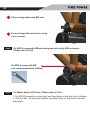
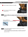
1. Fix M8*40 connection motor body and fixed block at this site, do not tighten.
2. With the M8 * 45 screw and tighten threaded holes on the fixed block and
fixed plate.
Fix M33.5 screw with BB axle using special tool by 40N·m torque.
Please refer to Pic3.
Step4
Fix Motor body with Frame. Please refer to Pic4.Step5
Put securing plate onto BB axle.
Fix securing plate and motor using
2 pcs screws.
Fix M33.5 screw with BB
axle using special tool (40N.m)
03
Pic2
Pic3

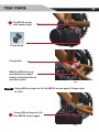
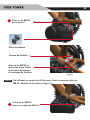
Using 40N.m torque to fix this M8*40 screw again. Please refer
to Pic5.
Step6
Fix M8*40 screw
with motor body
Fixed plate
With the M8*45 screw
and tighten threaded
holes on the fixed block
and fixed plate.
Using 40N.m torque to fix
this M8*40 screw again.
Fixed block
04
Pic4
Pic5

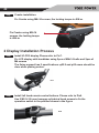
2 Display Installation Process
Cranks installation.
Step7
Install VLCD5 display. Please refer to Pic7.
Step1
Install left hand remote control buttons. Please refer to Pic8.Step2
Use 2 M2.5×10 inner hexagon cylindrical head screws to fix the
operation switch in the position shown in the figure
Fix Cranks using M8×14 screws, the locking torque is 40N.m.
Fix LCD display with handlebar using 2pcs of M4×14 bolts and 2pcs of
M4 screws
The fixing support has 2 specifications: φ22.2 and φ32 users should be
clear when placing orders.
Fix Cranks using M8×14
screws, the locking torque
is 40N.m.
05
Pic6
Pic7
Pic8

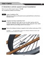
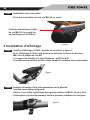
sensor Installation Pic9
Step1
magnetic steel base Installation Pic9
Step2
Ensure the distance between magnetic steel surface and sensor Pic9
Step3
CGQS8-------- not adjustable, ensure the distance between sensor and
magnetic steel surface is 5-15mm.
3: Detection vehicle speed sensor Installation
There is one vehicle speed sensor: CGQS8.
The installation method is as follows:
With the two ribbons will speed sensor pedestal fixed on the frame
flat after a fork
Install the magnetic steel seat on the rear wheel spokes with the
magnetic steel face toward the sensor and the magnetic steel center
aligned with the protruding mark on the sensor.
06
Pic9

plug in the operator and instrument.
Step1
plug the power brake into the base of the meter. This system can be
without power brake;
Step2
insert the plug-in of the instrument and the central motor.
Step3
insert the plug-in of the vehicle speed sensors and the central motor
Step4
connect the two power sources of the central motor to the battery.
Step5
4: System connection
07
1
5
4
2
3
For front light
For rear light

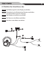
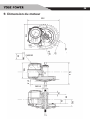
5: The wiring diagram
202
176
40
105
21.8
17
150
M33.5
14
68
34
50.2
M8X20
M8
Φ8.5
32
42
08

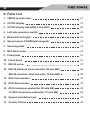
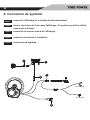
6: Parts List
1TSDZ2 central motor ×1
2VLCD5 display ×1
3VLCD5 display base(Ø22.5 and Ø32) ×2
4Left side operation switch ×1
5Brake(left and right) ×1
6Speed sensor CGQS8(with magnet) ×1
7Securing plate ×1
8M33.5mm screw ×1
9Fixed plate ×1
10Fixed block ×1
11M8×45 screw ×1
12M5×16 stainless steel screw(for 68 axle BB) ×2
M5×24 stainless steel screw(for 73 axle BB) ×2
13Ø35×1mm washer ×1
14Ø35×2mm washer ×1
15Ø5×5 aluminum washer(for 68 axle BB) ×2
Or Ø5×5 aluminum washer(for 73 axle BB) ×4
16Special installation tool ×1
17Cranks 170mm ×2
09

Motor Montage 12
Display Montage 14
Geschwindigkeitssensor Montage 15
Elektrischer Anschluss des Systems 16
Verkabelungsschema 16
Haupt- und Monatageabmessungen Motor 17
Teileliste 18
10

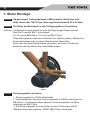
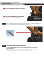
1: Motor Montage
Abmessungen Tretlagergehäuses (BB) ermitteln. Beite kann sein
68±0.15mm oder 73±0.15mm. Bohrungsdurchmesser Ø 33.6-33.8mm.
Sicherungsplatte montieren
Die Hülse der Motorwelle in das Tretlagergehäuse einschieben.
Achtung: 1.Motorwelle muss komplett bis zum Anschlag eingeschoben warden.
Das Maß X gemäß Bild 1 kontrollieren.
(X=16 mm bei BB=68mm, X=11mm bei BB=73mm).
2.Das Motorgehäuse darf keinen Kontakt zum Rahmen haben. Abstand zur
Hinterradschwinge oder sonstiger Rahmenrohre überprüfen.
Sonst kann sich das Motorgehäuse verformen, es können Geräusche
entstehen oder der Motor kann beschädigt warden.
1. Sicherungsplatte auf Welle aufschieben
2. Unterlegscheiben zwischen Sicherungsplatte und Motor anbringen bei
BB=68mm. 4 Unterlegscheiben zwischen Sicherungsplatte und Motor
anbringen bei BB=73mm.
3. Die Sicherungsplatte und den Motor mit den 2 Schrauben M5x16
(BB=68mm)beziehungsweise M5x24 (BB=73mm) befestigen.
Schritt1
Schritt2
Schritt3
11
Bilder1

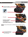
1. Den Fixierblock am Motor mit der Schraube M8x40 anschrauben.
Nicht festziehen !
2. Fixierblock am Rahmen mit Schraube M8x45 anschrauben und
anschließend Schraube zwischen Motor und Fixierblock
Gesamte Motoreinheit mittels Spezialwerkzeug und Mutter M33,5 mit
einem Drehmoment von 40 Nm festschrauben
Schritt4
Motorgehäuse am Rahmen befestigen.Schritt5
Sicherungsplatte auf Welle aufschieben
Die Sicherungsplatte umd dem Motor
mit den 2 schrauben befestigen
12
Bilder2
Bilder3

mit einem Drehmoment von 40Nmdie Schraube M8*40 festziehen
Schritt6
Die Schraube M8*40
am Motor anschrauben
Fixierplate
Fixierblock am Rahmen
mit Schraube M8x45
anschrauben und
anschließend Schraube
zwischen Motor und Fixierblock
mit einem Drehmoment
von 40Nmdie Schraube
M8*40 festziehen
Fixierblock
13
Bilder4
Bilder5

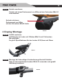
2 Display Montage
Kurbeln montieren.
Schritt7
VLCD5 montieren
Schritt1
Montage der linksseitigen Fernbedienungs Kontroll Schalter.Schritt2
Dazu 2 Innensechskantschrauben M2,5x10 verwenden und gemäß
Abbildung montieren
Kurbeln mit einem Drehmoment von 40Nm mit den Schrauben M8x14 f
estschrauben
LCD Display am Lenker mit 2 Bolzen M4x14 und 2 Schrauben
M4 befestigen.
Es gibt 2 Spezifikationen für den Lenker: Ø 22,2mm und 32mm
Kurbeln mit einem
Drehmoment von 40Nm
mit den Schrauben M8x14 festschrauben
14
Bilder6
Bilder7
Bilder8

Schritt1
Magnet montieren
Schritt2
Abstand 5-15mm zwischen Sensor und Magnet sicherstellen
Schritt3
CGQS8-------- Abstand 5-15mm zwischen Sensor und Magnet sicherstellen
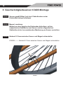
3: Geschwindigkeitssensor CGQS Montage
Sensor gemäß Bilder 9 mit den 2 Kabelbindern an der
Hinterradschwinge befestigen.
Magnet an einer Speiche des Hinterrades befestigen ,mit der
magnetischen Stahlfläche zum Sensor und der magnetischen
Stahlmitte mit der hervorstehenden Markierung am Sensor ausrichten.
15
Bilder9

Der Bedienungsteil an das Display anschließen
Schritt1
Bremshebel an die Rückseite des Displays anschließen,
ohne Bremshebel ist auch in Ordnung.
Schritt2
Das Display an den Motor anschließen
Schritt3
Der Sensor an den Motor anschließen
Schritt4
Den Akku an den Motor anschließen
Schritt5
4: Elektrischer Anschluss des
16
1
5
4
2
3
For front light
For rear light

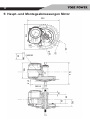
5: Haupt- und Montageabmessungen Motor
202
176
40
105
21.8
17
150
M33.5
14
68
34
50.2
M8X20
M8
Φ8.5
32
42
17

6: Parts List
1TSDZ2 Mitellmotor ×1
2VLCD5 display ×1
3VLCD5 display base(Ø22.5 and Ø32) ×2
4 Linker Fernbedienungsschalter ×1
5Bremshebel ×1
6Speed sensor CGQS8(mit Magnet) ×1
7Sicherungsplatte ×1
8M33.5mm Mutter ×1
9Fixierplate ×1
10Fixierblock ×1
11M8×45 Schrauben ×1
12M5×16 Schrauben(für 68 axle BB) ×2
M5×24 Schrauben(für 73 axle BB) ×2
13Ø35×1mm Unterlegscheibe ×1
14Ø35×2mm Unterlegscheibe ×1
15Ø5×5 aluminum washer(for 68 axle BB) ×2
Ø5×5 Unterlegscheibe (für 73 axle BB) ×4
16 Wergzeug ×1
17Kurbel 170mm ×2
18
Seite wird geladen ...
Seite wird geladen ...
Seite wird geladen ...
Seite wird geladen ...
Seite wird geladen ...
Seite wird geladen ...
Seite wird geladen ...
Seite wird geladen ...
Seite wird geladen ...
Seite wird geladen ...
-
 1
1
-
 2
2
-
 3
3
-
 4
4
-
 5
5
-
 6
6
-
 7
7
-
 8
8
-
 9
9
-
 10
10
-
 11
11
-
 12
12
-
 13
13
-
 14
14
-
 15
15
-
 16
16
-
 17
17
-
 18
18
-
 19
19
-
 20
20
-
 21
21
-
 22
22
-
 23
23
-
 24
24
-
 25
25
-
 26
26
-
 27
27
-
 28
28
-
 29
29
-
 30
30


YOSE POWER TSDZ2 Installationsanleitung
- Kategorie
- Wand
- Typ
- Installationsanleitung
in anderen Sprachen
- English: YOSE POWER TSDZ2 Installation guide
- français: YOSE POWER TSDZ2 Guide d'installation
