Tube Amp Doctor M100SL Assembly Instructions Manual
- Typ
- Assembly Instructions Manual

WARNUNG
ACHTUNG:
diese Bausätze sind keine Anfängerprojekte! Die Spannungen in einem Röhrenverstärker
können 500V und mehr betragen und sind somit bei unsachgemäßer Handhabung absolut
lebensbedrohlich!!!
Wir liefern lediglich eine komplette Zusammenstellung der benötigten Bauteile sowie einen
Schalt- und Layoutplan. Tube Amp Doctor bietet keinen grundsätzlichen Support für den
Aufbau an! Die Bausätze und deren Bestandteile sind sorgfältig geprüft und die zugrunde
liegenden Schaltungen sind seit über 40 Jahren in Gebrauch.
Für die Funktion der vom Kunden aufgebauten Geräte übernehmen wir keine Gewähr (für
die Bauteile selbst natürlich schon). Sollte der Aufbau zu unerwarteten Schwierigkeiten
führen, so kann die Tube Amp Doctor GmbH den Bausatz im Kundenauftrag fertig aufbauen
oder ggf. andere Service-Techniker vermitteln.
Fragen zu den Bausätzen werden wir auf der Tube Amp Doctor Web-Site unter FAQ
zusammenstellen um so ggf. Hilfestellung zu leisten.
WARNING
ATTENTION:
Please note that the Amp-Kit are not a beginners project but for experienced amp builders!
Voltages inside tube amplifiers can exceed 500V and can cause serious damage and can
even kill!
We only supply a complete compilation of excellent parts, a schematic and a layout
plan. Tube Amp Doctor does not offer a general support for you DIY project.
We do not warranty for what you build out of the supplied components. If you get stuck with
your DIY project then TAD might offer to finish assembly of your kit based on your service-
order or refer you to a skilled technician. Questions and answers about the AMP-KITS will
get collected and published at the F.A.Q. section at www.tubeampdoctor.com .
Tube Amp Doctor GmbH, Germany www.tubeampdoctor.com

24.07.2018, REV 2
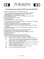
Verarbeitungvorschlag TAD Amp Kit M100SL
1. Materialien auspacken und auf Vollständigkeit prüfen.
2. Mit der Bestückung des Boards beginnen: zuerst Widerstände (0,5W),
Leistungswiderstände, Kondensatoren, Elektrolytkondensatoren.
3. Kabelverbindungen unter dem Board herstellen.
4. Kabelverbindungen zu anderen Teilen lt. beiliegender Liste herstellen.
5. Durchführtüllen einsetzen
6. Distanzbolzen am Chassis befestigen.
7. Netztrafo montieren.
8. Ausgangsübertrager und Drossel anbringen.
9. Potis (auch Biaspoti) mit Zahnscheiben einbauen, Orientierungsnase umbiegen.
(Frontpanel noch nicht montieren!!!)
10. Schalter, Kontrollleuchte einbauen, evtl. Plexipanel anpassen.
11. Röhrensockel montieren, auf korrekte Orientierung achten!
12. Netztrafo verdrahten, Heizleitungen unbedingt verdrillt verlegen, Oktalsockel
verdrahten.
13. Plexipanel der Rückseite ansetzten und Betriebsmittel einbauen, evtl. Panel
anpassen und verdrahten.
14. Radiale Elkos einbauen. Elko unter dem Board vorverdrahten.
15. Eingangsbuchsen vorverdrahten und danach einbauen.
16. Board einsetzen und lt. beiliegendem Verdrahtungsplan verdrahten.
17. Sicherungen einsetzten.
18. Röhren einsetzen
19. Funktionskontrolle durchführen, Ruhestrom einstellen.
20. Bohrungen am Gehäuse anzeichnen und Chassis einbauen:
20.1. Chassis bis zum Anschlag des Cabinets reinschieben.
20.2. Abstand des Chassis hinten zum Ende des Cabinets ausmessen.
20.3. Chassis wieder herausnehmen und Kopfüber AUF die Unterseite des
Cabinets legen. Vorher Gummifüße abschrauben. Den gemessenen
Abstand (siehe 2.) jetzt wieder herstellen.
20.4. Chassis mittig ausrichten, der Abstand links und rechts zum Ende des
Cabinets muss also gleich groß sein.
20.5. Durch die 4 Käfigmuttern nun anzeichnen bzw. körnen, so dass man
einen gut sichtbaren Abdruck hat.
20.6. Chassis wegnehmen und lotgerecht mit 6,5mm bohren.
20.7. Chassis einschieben und festschrauben.

24.07.2018, REV 2
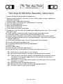
TAD Amp Kit M100SL Assembly Instructions
1. Unpack all material and check for completeness.
2. Begin to equip the board: start with resistors (0.5W), power resistors, condensers,
electrolytic capacitors.
3. Connect cables underneath the board.
4. Connect cables to the other parts according to list attached.
5. Put in all rubber grommets.
6. Mount distance bolt to the chassis.
7. Mount mains transformer.
8. Install output transformer and choke.
9. Embed pots (incl. bias-pot) with chopper disc, bend orientation nose. (Do not attach
front panel, yet!)
10. Install switches and control lamp; Plexipanel might need adjustments.
11. Install tube sockets - check for correct orientation/positioning.
12. Connect mains transformer, twist and lay heating cable, connect octal sockets.
13. Attach rear panel and connect the corresponding parts, adjustments to the panel
might be necessary.
14. Install radial electrolytic caps. Pre-wire them underneath the board.
15. Pre-wire input jacks and mount them.
16. Insert board and wire according to wiring diagram.
17. Install fuses.
18. Plug in tubes/valves.
19. Check function, make bias adjustments.
20. Mark drilling holes on the cabinet, drill holes and mount the chassis:
20.1. Push chassis into the cab as far as it will go.
20.2. Measure distance between the chassis and the end of the cabinet.
20.3. Take the chassis out again and put it upside down onto the bottom side of
the cabinet. Unscrew the rubber feet first. Re-establish the position as
measured earlier (20.2.)
20.4. Place chassis in the middle of the cabinet so the distance to the left and to
the right is the same.
20.5. Mark drilling holes through the cage nuts.
20.6. Remove the chassis and drill 6.5mm holes perpendicularly.
20.7. Put chassis back in and screw on tightly.

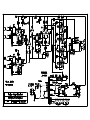
5K6
5K6
Red
Yellow
Red
Yellow
Red
Yellow
Red
Yellow
0,1uF
500pF
1M 1M
B25K
A1M
B5K
B250K
A1M
A1M
Loudness2Loudness1TrebleMiddleBassPresence Inputs1 2Power Standby
Black
100K
100K
68K
68K
68K
68K
820R
2K7
100K
470R
470K
470K
820R
33K
10K/1W
10K/1W
10K/1W
10K/1W
27K
8uF/475V
+
+
47K
15K
47K
100K
82K
220K
220K
1M
1M
10K
22nF
22nF
22nF
22nF
22nF
4n7nF
22nF
500pF
500pF
0,68u
250uF/25VBP
0,1uF
100K
50pF
1K 5W
1K 5W
1K 5W
1K 5W
5K6
5K6
56K/2W
56K/2W
OT
Brown
Red
Choke
Black
Black
5K6
Choke
OT
White
1
1
1
F
F
F
F1
F1
F1
F
F
F1
F1
F1
F1
F
F
F
F1
Black
Brown
Yellow
Black
White
Green
Green
PrimaryseeDetail
onseperatesheet
C
B
B
C
D
E
D
E
Black
Yellow
Green
Brown
OT
HT-Fuse Mains
Red
Yellow
G
G
Red
Yellow
B25K
Bias
ElectrolyticCapis
locatedundertheBoard
H
L
M
L
H
M
V1V2V3
V4
V5V6V7
Drawing:
Scale:
Drawn:
Units:
Date:
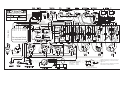
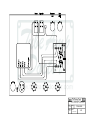
Plexi100WSuperLeadLayout
None
Mm
SM
04.05.17
ãTAD:
Forprivateuseonly
Donotcopy
1.23
8uF/475V
Regarding6,3VHeaters:
Use18AWG,Twisted
ToPIN2,7:EL34
ToPIN4-5,9:12AX7
Wires areCB3035,Yellow22AWG
Dottedwiresrunundertheboard
notspecified
PT:166-0903
Pleasestickprecislytothelayoutofthewiring!
especiallyregardingV1,otherwiseoscillation
canoccur!
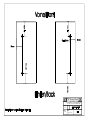
Mains-Input
Output

Drawing:
Scale:
Drawn:
Units:
Date:
None
SM
15.06.09
Plexi100W Super Lead Primary
1.22
PT:166-0903


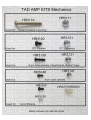
Drawing:
Scale:
Drawn:
Units:
Date:
1:2
SM
02.07.09
Bohrplan für K-ACM100W
Drills for K-ACM100W

-
 1
1
-
 2
2
-
 3
3
-
 4
4
-
 5
5
-
 6
6
-
 7
7
-
 8
8


Tube Amp Doctor M100SL Assembly Instructions Manual
- Typ
- Assembly Instructions Manual
in anderen Sprachen
- English: Tube Amp Doctor M100SL
Sonstige Unterlagen
-
Grundig TK 23 Bedienungsanleitung
-
Sharp CD-DD4500 Benutzerhandbuch
-
 YORKVILLE UCS1P Benutzerhandbuch
-
-
-
-
Hitachi CP2896TAN Benutzerhandbuch
-
Denon AVR-2311CI Benutzerhandbuch
-
