Bose AM301726 Benutzerhandbuch
- Kategorie
- Zusätzliche Musikausrüstung
- Typ
- Benutzerhandbuch
Dieses Handbuch ist auch geeignet für

©2007 Bose Corporation, The Mountain,
Framingham, MA 01701-9168 USA
AM301726 Rev.00
Owner’s Guide
Brugervejledning
Bedienungsanleitung
Guía de usario
Notice d’utilitsation
Manuale di istruzioni
Gebruiksaanwijzing
Bruksanvisningen
LIFESTYLE
®
VS-2
VIDEO ENHANCER
LIFESTYLE
®
VS–2 VIDEO ENHANCER
00_Cover_Lasik.fm Page 1 Thursday, October 26, 2006 11:47 AM

2
English
IMPORTANT SAFETY INSTRUCTIONS
1. Read these instructions.
2. Keep these instructions – for future reference.
3. Heed all warnings – on the product and in the owner’s guide.
4. Follow all instructions.
5. Do not use this apparatus near water – Do not use this product near a bathtub,
washbowl, kitchen sink, laundry tub, in a wet basement, near a swimming pool, or
anywhere else that water or moisture are present.
6. Clean only with a dry cloth – and as directed by Bose Corporation. Unplug this
product from the wall outlet before cleaning.
7. Do not block any ventilation openings. Install in accordance with the manu-
facturer’s instructions – To ensure reliable operation of the product and to protect it
from overheating, put the product in a position and location that will not interfere with
its proper ventilation. For example, do not place the product on a bed, sofa, or similar
surface that may block the ventilation openings. Do not put it in a built-in system,
such as a bookcase or a cabinet, that may keep air from flowing through its ventila
-
tion openings.
8. Do not install near any heat sources, such as radiators, heat registers, stoves
or other apparatus (including amplifiers) that produce heat.
9. Do not defeat the safety purpose of the polarized or grounding-type plug. A
polarized plug has two blades with one wider than the other. A grounding-
type plug has two blades and a third grounding prong. The wider blade or
third prong are provided for your safety. If the provided plug does not fit in
your outlet, consult an electrician for replacement of the obsolete outlet.
10. Protect the power cord from being walked on or pinched, particularly at
plugs, convenience receptacles, and the point where they exit from the
apparatus.
11. Only use attachments/accessories specified by the manufacturer.
12. Use only with the cart, stand, tripod, bracket, or table specified
by the manufacturer or sold with the apparatus. When a cart is
used, use caution when moving the cart/apparatus combination
to avoid injury from tip-over.
13. Unplug this apparatus during lightning storms or when unused
for long periods of time – to prevent damage to this product.
14. Refer all servicing to qualified service personnel. Servicing is required when
the apparatus has been damaged in any way, such as power-supply cord or
plug is damaged, liquid has been spilled or objects have fallen into the appa
-
ratus, the apparatus has been exposed to rain or moisture, does not operate
normally, or has been dropped – Do not attempt to service this product yourself.
Opening or removing covers may expose you to dangerous voltages or other haz
-
ards. Please call Bose to be referred to an authorized service center near you.
15. To prevent risk of fire or electric shock, avoid overloading wall outlets, exten-
sion cords, or integral convenience receptacles.
16. Do not let objects or liquids enter the product – as they may touch dangerous
voltage points or short-out parts that could result in a fire or electric shock.
17. See product enclosure bottom for safety-related markings.
Information about products that generate electrical noise
If applicable, this equipment has been tested and found to comply with the limits for a
Class B digital device, pursuant to Part 15 of the FCC rules. These limits are designed to
provide reasonable protection against harmful interference in a residential installation.
This equipment generates, uses, and can radiate radio frequency energy and, if not
installed and used in accordance with the instructions, may cause harmful interference to
radio communications. However, this is no guarantee that interference will not occur in a
particular installation. If this equipment does cause harmful interference to radio or televi
-
sion reception, which can be determined by turning the equipment off and on, you are
encouraged to try to correct the interference by one or more of the following measures:
• Reorient or relocate the receiving antenna.
• Increase the separation between the equipment and receiver.
• Connect the equipment to an outlet on a different circuit than the one to which the
receiver is connected.
• Consult the dealer or an experienced radio/TV technician for help.
Note: Unauthorized modification of the receiver or radio remote control could void the user’s
authority to operate this equipment.
This product complies with the Canadian ICES-003 Class B specifications.
00_LasikOG.book Page 2 Thursday, October 26, 2006 1:23 PM

3
English
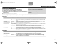
Please read this installation guide
Please take the time to follow this installation guide carefully. It will help you set
up and operate your system properly, and enjoy all of its advanced features. Save
your installation guide for future reference.
WARNING: To reduce the risk of fire or electric shock, do not expose the system to
rain or moisture.
WARNING: This apparatus shall not be exposed to dripping or splashing, and
objects filled with liquids, such as vases, shall not be placed on the apparatus. As
with any electronic products, use care not to spill liquids in any part of the system.
Liquids can cause a failure and/or a fire hazard.
CAUTION: No naked flame sources, such as lighted candles, should be placed on
the apparatus.
This product conforms to the EMC Directive 89/336/EEC and to the Low Voltage
Directive 73/23/EEC. The complete Declaration of Conformity can be found at
www.bose.com/static/compliance/index.html.
CONTENTS
Introduction . . . . . . . . . . . . . . . . . . . . . . . . . . . . . . . . . . . . . . . . . . . . . . . 4
Connecting the VS-2 to Your Media Center . . . . . . . . . . . . . . . . . . . . . . . 6
Your TV Connection Options . . . . . . . . . . . . . . . . . . . . . . . . . . . . . . . . . . 7
Using an HDMI TV Connection . . . . . . . . . . . . . . . . . . . . . . . . . . . . . . . . . 8
Using a Component Video TV Connection . . . . . . . . . . . . . . . . . . . . . . . 10
Using an S-Video TV Connection . . . . . . . . . . . . . . . . . . . . . . . . . . . . . . 12
Using a Composite Video TV Connection . . . . . . . . . . . . . . . . . . . . . . . . 14
Program Recording Connections . . . . . . . . . . . . . . . . . . . . . . . . . . . . . . 16
Operating Information . . . . . . . . . . . . . . . . . . . . . . . . . . . . . . . . . . . . . . 17
Mounting Your VS-2 on a Wall . . . . . . . . . . . . . . . . . . . . . . . . . . . . . . . . 20
Maintaining Your VS-2 . . . . . . . . . . . . . . . . . . . . . . . . . . . . . . . . . . . . . . 21
SAFETY INFORMATION
©2006
Bose Corporation. No part of this work may be reproduced, modified, distributed, or otherwise
used without prior written permission. All trademarks referenced herein are property of Bose Corporation.
HDMI, the HDMI logo and High-Definition Multimedia Interface are trademarks or registered trademarks
of HDMI Licensing LLC.
00_LasikOG.book Page 3 Thursday, October 26, 2006 1:23 PM

4
English
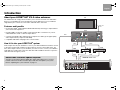
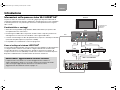
Introduction
About your LIFESTYLE
®
VS-2 video enhancer
The LIFESTYLE
®
VS-2 video enhancer allows you to connect more than one audio/video
device to your LIFESTYLE
®
home entertainment system. With this accessory installed, a
single button press selects the source video and audio at the same time.
Features and benefits
•Incorporates HDMI
TM
(High-Definition Multimedia Interface) technology to help maximize
your home theater experience.
• Provides HDMI, component, S-Video, and composite video connections for your TV,
cable/satellite box, VCR, or other A/V input devices.
• Converts lower-quality video input formats (composite or S-Video) up to higher quality
video output formats (component and HDMI).
• Compatible with HDTV and progressive scan TV formats.
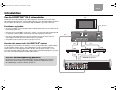
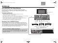
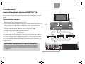
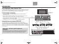
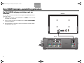
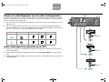
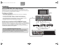
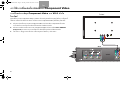
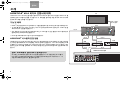
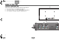
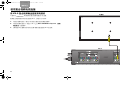
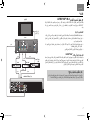
How it fits into your LIFESTYLE
®
system
Video outputs from all your A/V devices, such as your cable/satellite box and VCR, connect
to the VS-2, but the audio outputs from these devices connect to the media center. The
VS-2 video output connects to your TV. When you select a source, such as your cable box
(CBL•SAT), the media center selects the cable box audio and directs the VS-2 to pass the
cable box video through to your TV.
Video
Audio
Video
Video
Audio
Audio
AUX
CBL
•SAT
VCR
Video out
to TV
Video
TV
VS-2
LIFESTYLE
®
media center
IMPORTANT: Software update required!
Your VS-2 comes with a software update disc. After setting up the VS-2, you must
load this CD into the media center disc player and allow it to update your system.
Refer to “Updating the system software” on page 17.
00_LasikOG.book Page 4 Thursday, October 26, 2006 1:23 PM

5
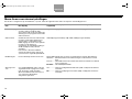
English
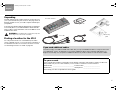
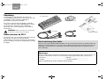
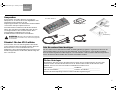
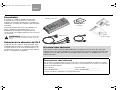
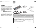
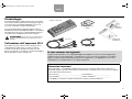
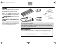
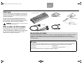
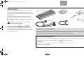
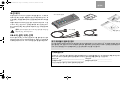
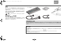
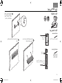
Unpacking
Carefully unpack the VS-2 video enhancer. Check to be sure
your system includes the parts shown on this page. Save all
packing materials in case you need to repack and transport
your product.
If any part of the product appears damaged, do not attempt to
use it. Notify Bose or your authorized Bose
®
dealer immedi-
ately. For Bose contact information, refer to the address sheet
included in the carton.
WARNING: To avoid danger of suffocation, keep the
plastic bags out of the reach of children.
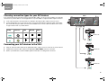
Finding a location for the VS-2
You can position the VS-2 on a shelf behind your media
center or behind your TV, or you can mount it on the back of
an entertainment center or on a wall. To mount it on a wall,
see
“Mounting Your VS-2 on a Wall” on page 20.
VS-2 video enhancer
VS-2 cable
For your records
Now is a good time to find the serial number on the bottom of the VS-2 video enhancer. Please record it here.
This provides easy access to this number if you ever need to contact Bose Customer Service.
Serial number: ________________________________ Purchase date: ________________________
Dealer name:__________________________________ Dealer phone: _________________________
Please keep your sales receipt with this owner’s guide.
If you need additional cables
Your VS-2 includes one HDMI-to-HDMI video cable, but you may need additional cables to set up the VS-2 with
your LIFESTYLE
®
system. To determine if you need any additional cables, please read this guide before you
begin the actual setup. You can purchase additional cables from your Bose dealer or local electronics retailer.
Software update disc
HDMI-to-HDMI cable
Owner’s
guide
Quick setup
guide
00_LasikOG.book Page 5 Thursday, October 26, 2006 1:23 PM

6
English
Connecting the VS-2 to Your Media Center
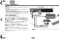
Preparation
When setting up a LIFESTYLE
®
system with the VS-2, the media center
power supply plugs into the VS-2 instead of the media center.
• If you are setting up the VS-2 and your LIFESTYLE
®
system at the
same time, find the media center power supply in the LIFESTYLE
system carton before you begin.
• If you are adding the VS-2 to an existing LIFESTYLE
®
system, turn
off your LIFESTYLE system, wait 30 seconds, and unplug the media
center power supply from the wall outlet. Then, disconnect the power
supply from the rear panel of the media center. Also, remove any video
cables from the Video OUT and Video IN connectors on the media center.
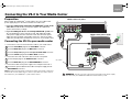
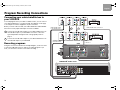
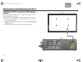
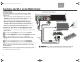
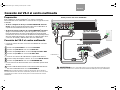
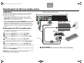
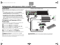
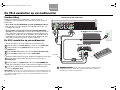
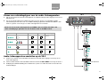
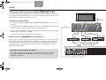
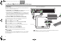
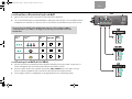
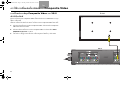
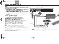
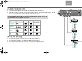
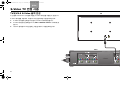
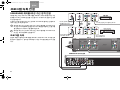
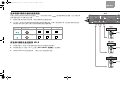
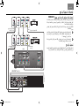
Connecting the VS-2 to your media center
VS-2 cable
VS-2 end panel
Media center power supply
Media center rear panel
WARNING: The VS-2 must be used only with the media center power supply
that came with your LIFESTYLE
®
DVD home entertainment system.
2
3
4
1
5
6
7
• Connect the 4-connector end of the VS-2 cable to your media center:
1 Insert the Serial Data plug into the Serial Data connector.
2 Insert the DC Power plug into the DC Power connector.
3 Insert the Composite plug into the Composite Video OUT connector.
4 Insert the S-Video plug into the S-Video OUT connector.
• Connect the other end of the VS-2 cable to the VS-2 end panel:
5 Insert multi-pin plug into the Media Center connector.
6 Insert the DC Power plug into the DC POWER Out connector.
• Connect the media center power supply to the end panel of the VS-2:
7 Insert the DC power cable from the media center power supply into the
DC POWER In connector.
Note: Straighten the DC power cord from the media center power supply and
from the VS-2 to the media center as much as possible. This cord is used as
the antenna for your LIFESTYLE
®
system remote control.
00_LasikOG.book Page 6 Thursday, October 26, 2006 1:23 PM

7
English
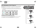
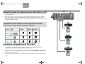
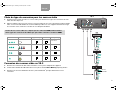
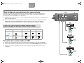
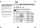
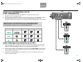
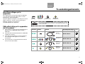
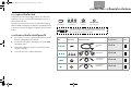
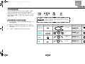
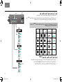
Your TV Connection Options
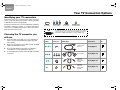
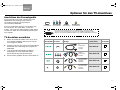
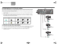
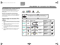
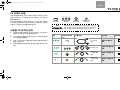
Identifying your TV connectors
Your TV may have some or all of the video input connectors
shown on the right. Each type of video connector provides
a different level of video image quality.
Examine the rear panel of your TV and determine whether it
has HDMI, component, S-Video, or composite video input
connectors. For additional instructions, refer to the owner’s
guide that came with your TV.
Choosing the TV connector you
will use
1. Using the table on the right, choose the available TV
video connector that provides the highest possible
video quality.
2. Make sure you have the correct cable on hand. An HDMI
cable is provided with the VS-2.
3. Go to the page listed for instructions on making the
connections to your TV and other A/V devices.
4. As a reminder, place a check mark in the table to indicate
your choice.
Composite
Standard quality
S-Video
Good quality
Component
Better quality
Video
Quality
TV Video
Connector Cable Type
Connection
Instructions
Check
One
Best HDMI
Go to page 8.
Better Component
Go to page 10.
Good S-Video
Go to page 12.
Standard Composite
Go to page 14.
Supplied with
the VS-2
Not supplied
Supplied
with your
LIFESTYLE
®
system
Supplied
with your
LIFESTYLE
®
system
HDMI
Best quality
DVI You may have a TV that has a DVI connector, but not an HDMI
connector. In this case, you still can use an HDMI connection by
using a DVI-to-HDMI cable adapter or a DVI-to-HDMI cable.
00_LasikOG.book Page 7 Thursday, October 26, 2006 1:23 PM

8
English
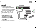
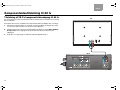
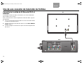
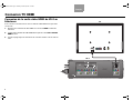
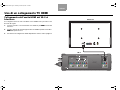
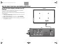
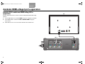
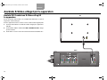
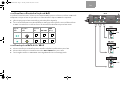
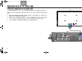
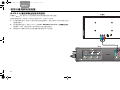
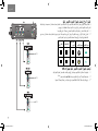
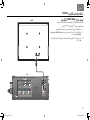
Using an HDMI TV Connection
Connecting the VS-2 HDMI output to your TV
To connect your TV to the VS-2 using the supplied HDMI cable, do the following:
1. Plug one end of the HDMI cable into the HDMI connector on the rear of your
TV.
2. Plug the other end of the HDMI cable into the Video OUTPUT HDMI connector
on the VS-2.
3. Go to page 9 for instructions on connecting other A/V devices to the VS-2.
TV
VS-2
00_LasikOG.book Page 8 Thursday, October 26, 2006 1:23 PM

9
English
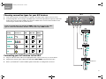
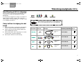
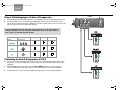
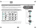
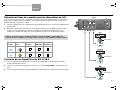
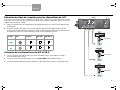
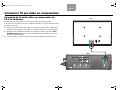
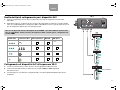
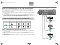
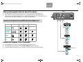
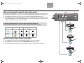
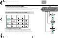
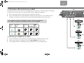
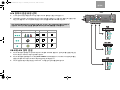
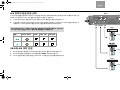
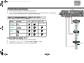
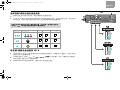
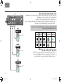
Choosing connection types for your A/V devices
1. Look at the rear panel of each A/V device to determine what type of video output connectors it has.
2. In the following table, choose the type of available video connector that provides the highest possible video
quality. We recommend using an HDMI connection if it is available. Place a check mark in the table for the
connector type used for each of your A/V devices.
Connecting your A/V devices to the VS-2
1. Plug one end of the video cable into the appropriate video output connector(s) on your A/V device.
2. Plug the other end of the video cable into the appropriate Video INPUT connector(s) on the VS-2.
3. Refer to your LIFESTYLE
®
system installation guide for information on making audio connections.
Video
Quality
Video
Connector VCR CBL•SAT
AUX
(Other)
Best HDMI
Not
available
on VS-2
Better Component
Good S-Video
Standard Composite
VS-2
DO NOT USE
If any of your A/V devices do not have an HDMI connector, you can use any other
type of connection. Remember, the VS-2 converts these up to HDMI format.
00_LasikOG.book Page 9 Thursday, October 26, 2006 1:23 PM

10
English
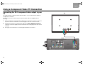
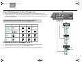
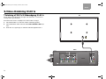
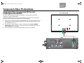
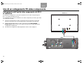
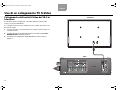
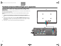
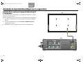
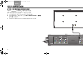
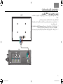
Using a Component Video TV Connection
Connecting the VS-2 component video output to your
TV
You need to obtain a component video cable from Bose or your local electronics dealer to
complete this connection.
To connect your TV to the VS-2 using a component video cable (not supplied), do the
following:
1. Plug one end of the component video cable into the component connectors on the rear
of your TV. Be sure to match the color of each plug to the color of each connector.
2. Plug the other end of the component video cable into the Video OUTPUT Component
connectors on the VS-2. Again, be sure to match the color of each plug to the color of each
connector.
3. Go to page 11 for instructions on connecting other A/V devices to the VS-2.
TV
VS-2
00_LasikOG.book Page 10 Thursday, October 26, 2006 1:23 PM

11
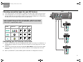
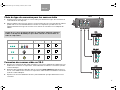
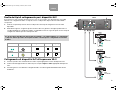
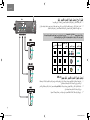
English
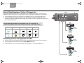
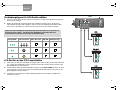
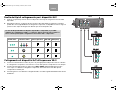
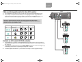
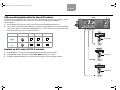
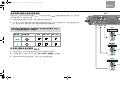
Choosing connection types for your A/V devices
1. Look at the rear panel of each A/V device to determine what type of video output connectors it has.
2. In the following table, choose the type of available video connector that provides the highest possi-
ble video quality. We recommend using a component connection if it is available. Place a check mark in
the table for the connector type used for each of your A/V devices.
Connecting your A/V devices to the VS-2
1. Plug one end of the video cable into the appropriate video output connector(s) on your A/V device. If
you are making a component connection, be sure to match the color of the plug to the color of the
connector.
2. Plug the other end of the video cable into the appropriate Video INPUT connector(s) on the VS-2. Again,
if you are making a component connection, be sure to match the color of the plug to the color of the
connector.
3. Refer to your LIFESTYLE
®
system installation guide for information on making audio connections.
Video
Quality
Video
Connector VCR CBL•SAT
AUX
(Other)
Better Component
Good S-Video
Standard Composite
VS-2
If any of your A/V devices do not have component video connectors, you can use
either an S-Video or Composite connection. Remember, the VS-2 converts either
of these up to component video format.
00_LasikOG.book Page 11 Thursday, October 26, 2006 1:23 PM

12
English
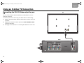
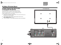
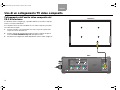
Using an S-Video TV Connection
Connecting the VS-2 S-Video output to your
TV
You can use the S-Video cable included with your LIFESTYLE
®
system to
make this connection.
To connect your TV to the VS-2 using an S-Video cable, do the following:
1. Plug one end of the S-Video cable into the S-Video connector on the rear
of your TV.
2. Plug the other end of the S-Video cable into the Video OUTPUT S-Video
connector on the VS-2.
3. Go to page 13 for instructions on connecting other A/V devices to the VS-2.
TV
VS-2
00_LasikOG.book Page 12 Thursday, October 26, 2006 1:23 PM

13
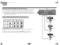
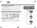
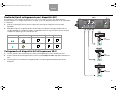
English
Choosing connection types for your A/V devices
If you connected your TV to the VS-2 using an S-Video cable, you can use only an S-Video or Composite con-
nection for your A/V devices even though a device may have HDMI or component video output connectors.
1. Look at the rear panel of each A/V device to determine what type of video output connectors it has.
2. In the following table, choose the type of video connector that provides the highest possible video quality.
We recommend using an S-Video connection if it is available. Place a check mark in the table for the connec
-
tor type used for each of your A/V devices.
Connecting your A/V devices to the VS-2
1. Plug one end of the video cable into the appropriate video output connector on the rear of your A/V
device.
2. Plug the other end of the video cable into the appropriate Video INPUT connector(s) on the VS-2.
3. Refer to your LIFESTYLE
®
system installation guide for information on making audio connections.
Video
Quality
Video
Connector VCR CBL•SAT
AUX
(Other)
Good S-Video
Standard Composite
DO NOT USE
DO NOT USE
DO NOT USE
VS-2
If any of your A/V devices do not have an S-Video connector, you can use a
Composite connector. Remember, the VS-2 converts this up to S-Video format.
00_LasikOG.book Page 13 Thursday, October 26, 2006 1:23 PM

14
English
Using a Composite Video TV Connection
Connecting the VS-2 composite video output
to your TV
You can use the composite video cable included with your LIFESTYLE
®
system to
make this connection.
To connect your TV to the VS-2 using a composite video cable, do the following:
1. Plug one end of the composite video cable into the composite video
connector on the rear of your TV.
2. Plug the other end of the composite video cable into the Video OUTPUT
Composite connector on the VS-2.
3. Go to page 15 for instructions on connecting other A/V devices to the VS-2.
TV
VS-2
00_LasikOG.book Page 14 Thursday, October 26, 2006 1:23 PM

15
English
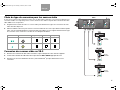
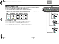
Choosing connection types for your A/V devices
If you connected your TV to the VS-2 using a composite video cable, you can use only an S-Video or Composite
connection for your A/V devices even though a device may have HDMI or component video output connectors.
1. Look at the rear panel of each A/V device to determine what type of video output connectors it has.
2. In the following table, choose the type of video connector that provides the highest possible video quality.
We recommend using an S-Video connection if it is available. Place a check mark in the table for the connec
-
tor type used for each of your A/V devices.
Connecting your A/V devices to the VS-2
1. Plug one end of the video cable into the appropriate video output connector on the rear of your A/V device.
2. Plug the other end of the video cable into the appropriate Video INPUT connector on the VS-2.
3. Refer to your LIFESTYLE
®
system installation guide for information on making audio connections.
Video
Quality
Video
Connector VCR CBL•SAT
AUX
(Other)
Good S-Video
Standard Composite
DO NOT USE
DO NOT USE
DO NOT USE
VS-2
00_LasikOG.book Page 15 Thursday, October 26, 2006 1:23 PM

16
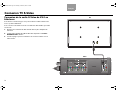
English
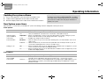
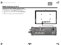
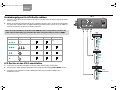
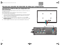
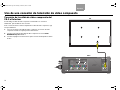
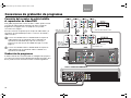
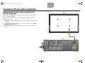
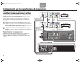
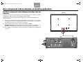
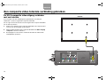
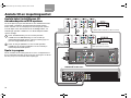
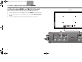
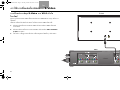
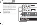
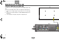
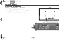
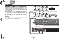
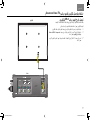
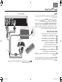
Program Recording Connections
Connecting your cable/satellite box to
your VCR/DVR
To record programs from your cable or satellite service, you can connect
your cable/satellite box to your VCR or DVR. The diagram on this page
is an example of how this equipment may be connected.
Before you start, make sure that your cable/satellite box and VCR/DVR
have the necessary input and output connectors available.
Connect an unused video output on your cable/satellite box to an
unused video input on your VCR/DVR. Choose the connection
type that provides the highest level of image quality. Refer to
page 7.
Connect an unused audio output on your cable/satellite box to an
unused audio input on your VCR/DVR.
Recording programs
Using the connection method in the example diagram, you do not need
to select the CBL•SAT source in order to record the program. If you
wish, you can listen to another source while recording.
1
2
VCR/DVR video
to the VS-2
Cable/satellite video to the VS-2
VCR/DVR audio to
the media center
Cable/satellite audio
to the media center
VS-2
LIFESTYLE
®
media center
1
2
00_LasikOG.book Page 16 Thursday, October 26, 2006 1:23 PM

17
English
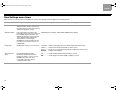
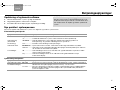
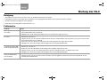
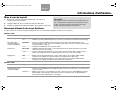
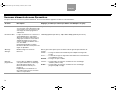
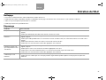
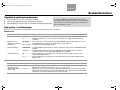
Operating Information
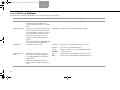
Updating the system software
1. Turn on your LIFESTYLE
®
system and select the CD/DVD source.
2. Load the software update disc into the media center disc player.
3. Wait for the display window of the media center to indicate when it is done.
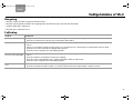
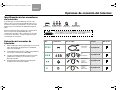
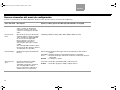
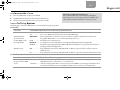
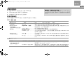
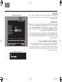
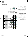
New System menu items
When the VS-2 is connected to your LIFESTYLE
®
system, the following new items will appear in the System menu.
Video options
Audio options
New Item Possible Settings (Factory/default settings in bold type)
Widescreen TV No..................... Tells your LIFESTYLE
®
system that it is connected to a 4:3 TV.
Yes .................... Tells your LIFESTYLE
®
system that it is connected to a 16:9 (widescreen) TV.
Video Resolution
(only for HDMI TV
connection)
Adjustable ......Allows your LIFESTYLE
®
system to select the optimal video resolution setting for your TV.
Refer to Video Resolution in “New Settings menu items” on page 18.
Fixed.................Prohibits any change to video resolution.
Persistent Video Disabled .......... Removes video from your TV screen when switching from your selected video source to an
audio source.
Enabled............. Allows the video from your selected source (CBL•SAT, VCR, or AUX) to remain on your TV
screen when switching from this source to an audio source.
Settings on TV Yes ...................Allows the Settings menu for the TV, CBL•SAT, VCR, and AUX sources to appear on your TV
screen as well as on the media center display window.
No .....................Allows the Settings menu for the TV, CBL•SAT, VCR, and AUX sources to appear only on the
media center display window.
New Item Possible Settings (Factory/default settings in bold type)
CBL•SAT/VCR Audio
(only for HDMI
connections)
Bose 5.1 ..........Allows you to hear 5.1-channel surround sound from your LIFESTYLE
®
system when the
selected source is CBL•SAT or VCR. Recommended setting – should not be changed.
TV Stereo ..........Tells the VS-2 to send two-channel digital audio received (through an HDMI cable) from your
cable/satellite box or VCR to your TV (through an HDMI cable). The LIFESTYLE
®
system
speakers are silent.
IMPORTANT: Software update required!
Your VS-2 comes with a software update disc. To enable
the media center to operate with the VS-2, you must load
this CD into the media center disc player and allow it to
update your system.
00_LasikOG.book Page 17 Thursday, October 26, 2006 1:23 PM

18
English
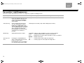
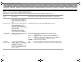
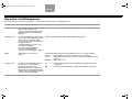
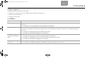
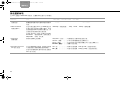
New Settings menu items
When the VS-2 is connected to your LIFESTYLE
®
system, the following new items appear in the Settings menu.
New Menu Item Description Possible Settings (Factory/default settings in bold type)
Audio Delay Changes the amount of delay between
audio and video. Used to synchronize
the audio with the action when viewing
audio/video program content.
0 (no delay), 1, 2, 3, 4, 5, 6, 7, 8 (maximum delay)
Video Resolution Lists output video resolutions sup-
ported by your TV when it is connected
to the HDMI output of the VS-2. The
optimal resolution for your TV is listed
as the default setting and remains
selected unless you change it.
Available only when the Video Resolu-
tion option in the System menu is set
to Adjustable.
480/576p (lowest quality), 720p, 1080i, 1080p (highest quality)
Image View Modifies the image on your TV screen. Gray Bars ....Adds a vertical gray bar to the left and right side of the image.
Stretch ........Stretches the image horizontally to fit the screen.
Zoom ..........Image size is increased horizontally and vertically to fit the screen.
Normal .......Image is not changed.
SD Progressive
Scan
For standard-definition video,
determines whether interlaced or
progressive video is sent to your TV.
Available only when your TV is
connected to the VS-2 using a
component video cable.
Off ...............Sends interlaced video (480i or 576i) to your TV.
On ...............Sends progressive video (480p or 576p) to your TV.
00_LasikOG.book Page 18 Thursday, October 26, 2006 1:23 PM

19
English
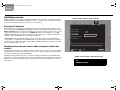
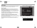
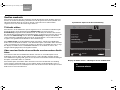
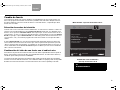
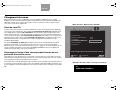
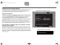
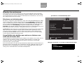
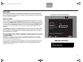
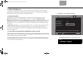
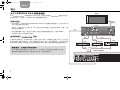
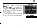
Switching sources
Adding the VS-2 to your system setup greatly simplifies source selection. Just press the remote
button (CD/DVD, VCR, CBL•SAT, or AUX) for the source you want to use. If you select one of the
sources connected to the VS-2, be sure the source is turned on.
Selecting TV channels
When the VS-2 is connected to your LIFESTYLE
®
system, the remote changes channels on the
source selected by the TV Control setting (CBL•SAT, VCR, TV, or AUX) in the System menu under
Remote Control options. This means that when you select the TV source on the remote, you see
and hear the TV channel coming from your TV Control selection. For example, if you set TV
control to CBL•SAT and press the TV source button on your remote, you will see and hear the
program on the selected channel of your cable or satellite box.
If TV Control is set to TV (default setting), your TV screen goes blank when selecting the TV
source unless you enable the Persistent Video option (see
“New System menu items” on page 17).
If your TV screen is blank, the media center displays CHOOSE TV INPUT to remind you to select
the correct video input on your TV.
Watching video from one source while listening to audio from
another
Normally, when you switch to an audio source from a video source, your TV screen goes blank. To
change this so the video source remains on your TV screen, go to the System menu and change
the Persistent Video option setting to Enabled.
Enabling Persistent Video allows you to continue viewing the video portion of a program while
listening to the audio from another source, such as FM or AM radio. For example, you can watch a
ball game on your TV while listening to the broadcast audio of the same ball game from a local
radio station.
TV
CHOOSE TV INPUT
navigate
select
Choose the device that you have connected to the TV Audio IN jacks.
AUX Device:
AUX Brand:
AUX Code:
TV Control:
Remote Version
IR Control:
AUX
VCR
CBL•SAT
TV
Remote Control
Media center display – blank TV message
System menu – Remote Control options
00_LasikOG.book Page 19 Thursday, October 26, 2006 1:23 PM

20
English
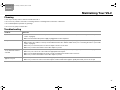
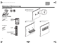
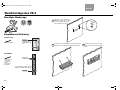
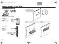
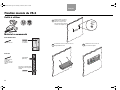
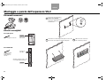
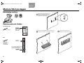
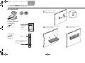
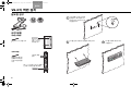
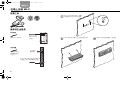
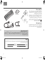
Mounting Your VS-2 on a Wall
Required tools
Recommended hardware
Install two screws eight inches apart.
Leave ¼ inch (6 mm) between wall
surface and screw head.
Position the VS-2 mounting holes over the
screws so that it is flush with the wall.
Lower the VS-2 onto the screws
to lock it in place.
1
2
3
For solid wood
For wallboard
-inch (3.5 mm) drill bit
1
8
Use drill size
specified for type
of wall anchor
used.
No. 8 x 1½-inch
(M4 x 36 mm)
wood screws
No. 8 x 1½-inch (M4 x 36 mm)
wood or machine screws (depends
on type of wall anchor)
No. 8 (M4)
wall anchor
00_LasikOG.book Page 20 Thursday, October 26, 2006 1:23 PM
Seite laden ...
Seite laden ...
Seite laden ...
Seite laden ...
Seite laden ...
Seite laden ...
Seite laden ...
Seite laden ...
Seite laden ...
Seite laden ...
Seite laden ...
Seite laden ...
Seite laden ...
Seite laden ...
Seite laden ...
Seite laden ...
Seite laden ...
Seite laden ...
Seite laden ...
Seite laden ...
Seite laden ...
Seite laden ...
Seite laden ...
Seite laden ...
Seite laden ...
Seite laden ...
Seite laden ...
Seite laden ...
Seite laden ...
Seite laden ...
Seite laden ...
Seite laden ...
Seite laden ...
Seite laden ...
Seite laden ...
Seite laden ...
Seite laden ...
Seite laden ...
Seite laden ...
Seite laden ...
Seite laden ...
Seite laden ...
Seite laden ...
Seite laden ...
Seite laden ...
Seite laden ...
Seite laden ...
Seite laden ...
Seite laden ...
Seite laden ...
Seite laden ...
Seite laden ...
Seite laden ...
Seite laden ...
Seite laden ...
Seite laden ...
Seite laden ...
Seite laden ...
Seite laden ...
Seite laden ...
Seite laden ...
Seite laden ...
Seite laden ...
Seite laden ...
Seite laden ...
Seite laden ...
Seite laden ...
Seite laden ...
Seite laden ...
Seite laden ...
Seite laden ...
Seite laden ...
Seite laden ...
Seite laden ...
Seite laden ...
Seite laden ...
Seite laden ...
Seite laden ...
Seite laden ...
Seite laden ...
Seite laden ...
Seite laden ...
Seite laden ...
Seite laden ...
Seite laden ...
Seite laden ...
Seite laden ...
Seite laden ...
Seite laden ...
Seite laden ...
Seite laden ...
Seite laden ...
Seite laden ...
Seite laden ...
Seite laden ...
Seite laden ...
Seite laden ...
Seite laden ...
Seite laden ...
Seite laden ...
Seite laden ...
Seite laden ...
Seite laden ...
Seite laden ...
Seite laden ...
Seite laden ...
Seite laden ...
Seite laden ...
Seite laden ...
Seite laden ...
Seite laden ...
Seite laden ...
Seite laden ...
Seite laden ...
Seite laden ...
Seite laden ...
Seite laden ...
Seite laden ...
Seite laden ...
Seite laden ...
Seite laden ...
Seite laden ...
Seite laden ...
Seite laden ...
Seite laden ...
Seite laden ...
Seite laden ...
Seite laden ...
Seite laden ...
Seite laden ...
Seite laden ...
Seite laden ...
Seite laden ...
Seite laden ...
Seite laden ...
Seite laden ...
Seite laden ...
Seite laden ...
Seite laden ...
Seite laden ...
Seite laden ...
Seite laden ...
Seite laden ...
Seite laden ...
Seite laden ...
Seite laden ...
Seite laden ...
Seite laden ...
Seite laden ...
Seite laden ...
Seite laden ...
Seite laden ...
Seite laden ...
Seite laden ...
Seite laden ...
Seite laden ...
Seite laden ...
Seite laden ...
Seite laden ...
Seite laden ...
Seite laden ...
Seite laden ...
Seite laden ...
Seite laden ...
Seite laden ...
Seite laden ...
Seite laden ...
Seite laden ...
Seite laden ...
Seite laden ...
Seite laden ...
Seite laden ...
Seite laden ...
Seite laden ...
Seite laden ...
Seite laden ...
Seite laden ...
Seite laden ...
Seite laden ...
Seite laden ...
Seite laden ...
Seite laden ...
Seite laden ...
Seite laden ...
Seite laden ...
Seite laden ...
Seite laden ...
Seite laden ...
Seite laden ...
Seite laden ...
Seite laden ...
Seite laden ...
Seite laden ...
Seite laden ...
Seite laden ...
Seite laden ...
Seite laden ...
Seite laden ...
Seite laden ...
Seite laden ...
Seite laden ...
Seite laden ...
Seite laden ...
Seite laden ...
Seite laden ...
Seite laden ...
Seite laden ...
Seite laden ...
Seite laden ...
Seite laden ...
Seite laden ...
Seite laden ...
Seite laden ...
Seite laden ...
Seite laden ...
Seite laden ...
Seite laden ...
Seite laden ...
Seite laden ...
Seite laden ...
Seite laden ...
Seite laden ...
Seite laden ...
Seite laden ...
Seite laden ...
Seite laden ...
Seite laden ...
Seite laden ...
Seite laden ...
Seite laden ...
Seite laden ...
Seite laden ...
Seite laden ...
Seite laden ...
Seite laden ...
Seite laden ...
Seite laden ...
Seite laden ...
Seite laden ...
Seite laden ...
Seite laden ...
Seite laden ...
Seite laden ...
Seite laden ...
Seite laden ...
Seite laden ...
Seite laden ...
-
 1
1
-
 2
2
-
 3
3
-
 4
4
-
 5
5
-
 6
6
-
 7
7
-
 8
8
-
 9
9
-
 10
10
-
 11
11
-
 12
12
-
 13
13
-
 14
14
-
 15
15
-
 16
16
-
 17
17
-
 18
18
-
 19
19
-
 20
20
-
 21
21
-
 22
22
-
 23
23
-
 24
24
-
 25
25
-
 26
26
-
 27
27
-
 28
28
-
 29
29
-
 30
30
-
 31
31
-
 32
32
-
 33
33
-
 34
34
-
 35
35
-
 36
36
-
 37
37
-
 38
38
-
 39
39
-
 40
40
-
 41
41
-
 42
42
-
 43
43
-
 44
44
-
 45
45
-
 46
46
-
 47
47
-
 48
48
-
 49
49
-
 50
50
-
 51
51
-
 52
52
-
 53
53
-
 54
54
-
 55
55
-
 56
56
-
 57
57
-
 58
58
-
 59
59
-
 60
60
-
 61
61
-
 62
62
-
 63
63
-
 64
64
-
 65
65
-
 66
66
-
 67
67
-
 68
68
-
 69
69
-
 70
70
-
 71
71
-
 72
72
-
 73
73
-
 74
74
-
 75
75
-
 76
76
-
 77
77
-
 78
78
-
 79
79
-
 80
80
-
 81
81
-
 82
82
-
 83
83
-
 84
84
-
 85
85
-
 86
86
-
 87
87
-
 88
88
-
 89
89
-
 90
90
-
 91
91
-
 92
92
-
 93
93
-
 94
94
-
 95
95
-
 96
96
-
 97
97
-
 98
98
-
 99
99
-
 100
100
-
 101
101
-
 102
102
-
 103
103
-
 104
104
-
 105
105
-
 106
106
-
 107
107
-
 108
108
-
 109
109
-
 110
110
-
 111
111
-
 112
112
-
 113
113
-
 114
114
-
 115
115
-
 116
116
-
 117
117
-
 118
118
-
 119
119
-
 120
120
-
 121
121
-
 122
122
-
 123
123
-
 124
124
-
 125
125
-
 126
126
-
 127
127
-
 128
128
-
 129
129
-
 130
130
-
 131
131
-
 132
132
-
 133
133
-
 134
134
-
 135
135
-
 136
136
-
 137
137
-
 138
138
-
 139
139
-
 140
140
-
 141
141
-
 142
142
-
 143
143
-
 144
144
-
 145
145
-
 146
146
-
 147
147
-
 148
148
-
 149
149
-
 150
150
-
 151
151
-
 152
152
-
 153
153
-
 154
154
-
 155
155
-
 156
156
-
 157
157
-
 158
158
-
 159
159
-
 160
160
-
 161
161
-
 162
162
-
 163
163
-
 164
164
-
 165
165
-
 166
166
-
 167
167
-
 168
168
-
 169
169
-
 170
170
-
 171
171
-
 172
172
-
 173
173
-
 174
174
-
 175
175
-
 176
176
-
 177
177
-
 178
178
-
 179
179
-
 180
180
-
 181
181
-
 182
182
-
 183
183
-
 184
184
-
 185
185
-
 186
186
-
 187
187
-
 188
188
-
 189
189
-
 190
190
-
 191
191
-
 192
192
-
 193
193
-
 194
194
-
 195
195
-
 196
196
-
 197
197
-
 198
198
-
 199
199
-
 200
200
-
 201
201
-
 202
202
-
 203
203
-
 204
204
-
 205
205
-
 206
206
-
 207
207
-
 208
208
-
 209
209
-
 210
210
-
 211
211
-
 212
212
-
 213
213
-
 214
214
-
 215
215
-
 216
216
-
 217
217
-
 218
218
-
 219
219
-
 220
220
-
 221
221
-
 222
222
-
 223
223
-
 224
224
-
 225
225
-
 226
226
-
 227
227
-
 228
228
-
 229
229
-
 230
230
-
 231
231
-
 232
232
-
 233
233
-
 234
234
-
 235
235
-
 236
236
-
 237
237
-
 238
238
-
 239
239
-
 240
240
-
 241
241
-
 242
242
-
 243
243
-
 244
244
-
 245
245
-
 246
246
-
 247
247
-
 248
248
-
 249
249
-
 250
250
-
 251
251
-
 252
252
-
 253
253
-
 254
254
-
 255
255
-
 256
256
-
 257
257
-
 258
258
-
 259
259
-
 260
260
-
 261
261
-
 262
262
-
 263
263
-
 264
264
-
 265
265
-
 266
266
-
 267
267


Bose AM301726 Benutzerhandbuch
- Kategorie
- Zusätzliche Musikausrüstung
- Typ
- Benutzerhandbuch
- Dieses Handbuch ist auch geeignet für
in anderen Sprachen
- français: Bose AM301726 Manuel utilisateur
- español: Bose AM301726 Manual de usuario
- italiano: Bose AM301726 Manuale utente
- Nederlands: Bose AM301726 Handleiding
- dansk: Bose AM301726 Brugermanual
Verwandte Papiere
Sonstige Unterlagen
-
Yamaha RV2600 DTS Benutzerhandbuch
-
Yamaha DSP-Z11 Bedienungsanleitung
-
Yamaha RX-V563 Benutzerhandbuch
-
Yamaha RXV2700BL Bedienungsanleitung
-
-
Yamaha RX V3900 - AV Network Receiver Benutzerhandbuch
-
Yamaha RX-V863 Bedienungsanleitung
-
-
Philips SWA3162S/10 Benutzerhandbuch