Hitachi CS40EM Bedienungsanleitung
- Kategorie
- Kraftkettensägen
- Typ
- Bedienungsanleitung
Dieses Handbuch eignet sich auch für

GB
FR
IT
DE
ES
NL
PT
GR
GB
OWNER’S MANUAL
FR
MODE D’EMPLOI
IT
MANUALE D’ISTRUZIONI
DE
BEDIENUNGSANLEITUNG
ES
MANUAL DEL PROPIETARIO
NL
GEBRUIKSAANWIJZING
PT
MANUAL DO PROPRIETÁRIO
GR
∆ΗΓΙΕΣ ΡΗΣΗΣ
CHAINSAWS
TRONÇONNEUSES
MOTOSEGHE
MOTORKETTENSÄGEN
MOTOSIERRAS
MOTORZAGEN
MOTOSSERRAS
ΑΛΥΣΠΡΙΝΑ
CS40EM/45EM
970-82831-200 2007.07
G
B
I
T
E
S
F
R
D
E
N
L
P
T
G
R

G
B
GB-1
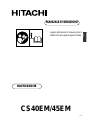
CS40EM/45EM
OWNER’S MANUAL
CHAIN SAWS
Read the manual carefully before
operating this machine.

GB-2
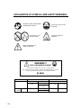
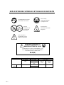
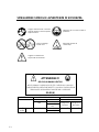
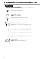
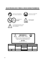
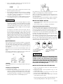
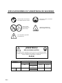
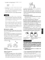
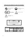
EXPLANATION OF SYMBOLS AND SAFETY WARNINGS
WARNING!!!
RISK OF DAMAGING HEARING
IN NORMAL CONDITIONS OF USE, THIS MACHINE
MAY INVOLVE A DAILY LEVEL OF PERSONAL EXPOSURE TO NOISE
FOR THE OPERATOR EQUAL TO OR GREATER THAN
85 dB(A)
Read the manual carefully before
operating this machine.
Wear head, eye and ear
protection.
Use the chain saw
with two hands.
Warning! Danger of
kickback.
Read, understand and
follow all warnings.
MODEL
CS40EM 49.3 cm
3
/45EM
SOUND LEVEL
VIBRATION LEVEL
ISO 22868
LpA
ISO 22868
Lw measured
2000/14/EC
LwA
103.6 dB(A)
110 dB(A)
ISO 22867
100.8 dB(A)
Front handle Rear handle
5.5 m/s
2
7.2 m/s
2

G
B
GB-3
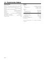
Contents
1. For Safe Operation ................................................................... 4
2. Explanation of Symbols on the Machine .................................. 6
3. Description ............................................................................... 7
4. Installing Guide Bar and Saw Chain......................................... 8
5. Fuel and Chain Oil .................................................................... 9
6. Operating the Engine ............................................................. 10
7. Sawing .................................................................................... 12
8. Maintenance ........................................................................... 13
9. Maintenance of Saw Chain and Guide Bar ............................ 14
10. Troubleshooting Guide ........................................................... 15
11. Specifications ......................................................................... 16
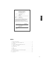
Yoshio Osada
Director
Signed in Chiba, Japan
DECLARATION OF CONFORMITY
(Directive 98/37/EC, EMC 89/336/EEC)
and to the regulations governing transposition
Internal control production
MANUFACTURER : Nikko Tanaka Engineering Co.,LTD
3-4-29 Tsudanuma
Narashino
Chiba, JAPAN
DECLARES THAT THE DESIGN OF THE MACHINE DESCRIBED BELOW :
Model : CS40EM/45EM
Serial no. : E57001 and up
Make : Nikko Tanaka Engineering
CONFORMS TO THE REQUIRMENTS OF THE MODIFIED MACHINES
DIRECTIVE (Directive 98/37/EC, EMC 89/336/EEC) AND TO THE NATIONAL
REGULATIONS GOVERNING ITS TRANSPOSITION ABROAD (ISO11681-1,
ISO12100-1 and -2, CISPR 12) : AND
THAT IT HAS BEEN ISSUED WITH A CE CERTIFICATE, NO. 404/05/1070
BY 404, SMP Svensk MaskinprovningAB, Fyrisborgsgaian 3, SE-754 50, Uppsala,
Sweden.
05/01/2007

GB-4
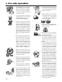
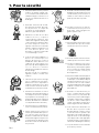
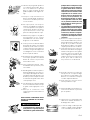
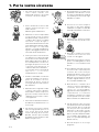
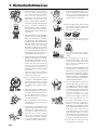
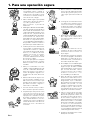
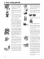
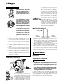
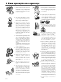
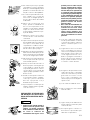
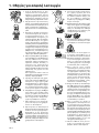
1. For safe operation
1. Never operate a chain saw when
you are fatigued, ill, or upset, or
under the influence of medica-
tion that may make you drowsy,
or if you are under the influence
of alcohol or drugs.
2. Use safety footwear, snug fitting
clothing and eye, hearing and
head protection devices.
Use the vibration-proof glove.
3. Keep the saw chain sharp and
the saw, including the AV system,
well maintained. A dull chain will
increase cutting time, and press-
ing a dull chain through wood will
increase the vibrations transmit-
ted to your hands. A saw with
loose components or with dam-
aged or worn AV buffers will also
tend to have higher vibration lev-
els.
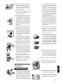
4. All the above mentioned precau-
tions do not guarantee that you
will not sustain whitefinger
diseaseor carpal tunnel syn-
drome. Therefore, continual and
regular users should monitor
closely the condition of their
hands and fingers. If any of the
above symptoms appear, seek
medical advice immediately.
5. Always use caution when han-
dling fuel. Wipe up all spills and
then move the chain saw at least
3 m from the fueling point before
starting the engine.
6. Eliminate all sources of sparks or
flame (i.e. smoking, open flames,
or work that can cause sparks)
in the areas where fuel is mixed,
poured, or stored.
7. Do not smoke while handling fuel
or while operating the chain saw.
8. Do not allow other persons to be
near the chain saw when start-
ing or cutting. Keep bystanders
and animals out of the work area.
Children, pets and bystanders
should be a minimum of 10 m
away when you start or operate
the chain saw.
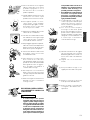
9. Never start cutting until you have
a clear work area, secure foot-
ing, and a planned retreat path
from the falling tree.
10. Always hold the chain saw firmly
with both hands when the engine
is running. Use a firm grip with
thumb and fingers encircling the
chain saw handles.
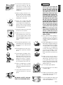
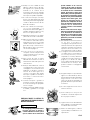
11. Keep all parts of your body away
from the saw chain when the en-
gine is running.
12.Before you start the engine,
make sure the saw chain is not
contacting anything.
13. Always carry the chain saw with
the engine stopped, the guide
bar and saw chain to the rear,
and the muffler away from your
body.
14. Never modify the unit or remove
the safety components in any way.
Do not use your unit for any job
except that for which it is intended.
Use only genuine HITACHI re-
placement parts as recom-
mended by the manufacturer.
15. Always inspect the chain saw be-
fore each use for worn, loose, or
damaged parts. Never operate
a chain saw that is damaged, im-
properly adjusted, or is not com-
pletely and securely assembled.
Be sure that the saw chain stops
moving when the throttle control
trigger is released.
16. All chain saw service, other than
the items listed in the Owner’s
Manual, should be performed by
competent chain saw service
personnel. (E.g., if improper tools
are used to remove the flywheel,
or if an improper tool is used to
hold the flywheel in order to re-
move the clutch, structural dam-
age to the flywheel could occur
which could subsequently cause
the flywheel to disintegrate.)
17. Always shut off the engine be-
fore setting it down.

G
B
GB-5
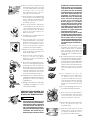
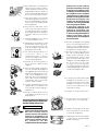
18. Use extreme caution when cut-
ting small size brush and sap-
lings because slender material
may catch the saw chain and be
whipped toward you or pull you
off balance.
19. When cutting a limb that is un-
der tension, be alert for spring-
back so that you will not be
struck when the tension in the
wood fibers is released.
20. Never cut in high wind, bad
weather, when visibility is poor or
in very high or low temperatures.
Always check the tree for dead
branches which could fall during
the felling operation.
21. Keep the handles dry, clean and
free of oil or fuel mixture.
22. Operate the chain saw only in
well ventilated areas. Never start
or run the engine inside a closed
room or building. Exhaust fumes
contain dangerous carbon mon-
oxide.
23. For respiratory protection, wear
a protection mask while emitting
the chain oil mist and dust from
sawdust.
24. Do not operate the chain saw in
a tree unless specially trained to
do so.
25. Guard against kickback. Kick-
back is the upward motion of the
guide bar which occurs when the
saw chain at the nose of the
guide bar contacts an object.
Kickback can lead to dangerous
loss of control of the chain saw.
26.When transporting or storage
your chain saw, make sure the
appropriate guide bar protector
is in place.
27. Clean and maintenance the unit
carefully and store it in the dry
place.
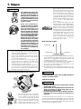
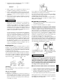
KICKBACK SAFETY PRECAU-
TIONS FOR CHAIN SAW USERS
WARNING
• Kickback may occur when the
nose or tip of the guide bar
touches an object, or when the
wood closes in and pinches the
saw chain in the cut. Tip con-
tact in some cases may cause
a lightning fast reverse reac-
tion, kicking the guide bar up
and back towards the operator.
Pinching the saw chain along
the top of the guide bar may
push the guide bar rapidly back
towards the operator. Either of
these reactions may cause you
to lose control of the saw, which
could result in serious personal
injury.
• Do not rely exclusively on the
safety devices built into your
saw. As a chain saw user you
should take several steps to
keep cutting jobs free from ac-
cident or injury.
(1) With a basic understanding of
kickback you can reduce or
eliminate the element of surprise.
Sudden surprise contributes to
accidents.
(2) Keep a good grip on the saw with
both hands, the right hand on the
rear handle, and the left hand on
the front handle, when the engine
is running. Use a firm grip with
thumbs and fingers encircling
the chain saw handles. A firm
grip will help you reduce kick-
back and maintain control of the
saw.
(3) Make certain that the area in
which you are cutting is free from
obstructions. Do not let the nose
of the guide bar contact a log,
branch, or any other obstruction
which could be hit while you are
operating the saw.
(4) Cut at high engine speeds.
(5) Do not overreach or cut above
shoulder height.
(6) Follow the manufacturer’s sharp-
ening and maintenance instruc-
tions for the saw chain.
(7) Only use replacement bars and
chains specified by the manufac-
turer or the equivalent.

GB-6
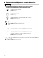
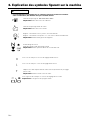
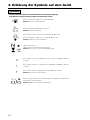
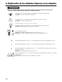
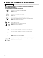
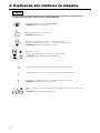
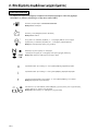
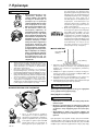
2. Explanation of Symbols on the Machine
WARNING
• For safe operation and maintenance, symbols are carved in relief on the machine.
According to these indications, please be careful not to make any mistake.
The screw under the “H” stamp is The High-speed adjustment screw.
The port to refuel “MIX GASOLINE”
Position: Fuel cap
The port to top up chain oil
Position: Oil cap
Setting the switch to the “ | ” position, the engine starts.
Setting the switch to the “O” position, the engine stops immediately.
Position: Rear-left of the unit
Starting the engine.
Starting mode when the engine is cold. (cold start)
Position: Upper-right of the aircleaner cover
Shows the directions that the chain brake is released (white arrow) and activated (black ar-
row).
Position: Front of the chain cover
The screw at the left of the “T” stamp is the Idle adjustment screw.
Position: Left side of the rear handle
The screw under the “L” stamp is The Slow-speed adjustment screw.

G
B
GB-7
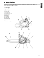
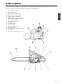
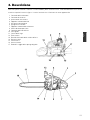
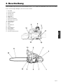
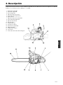
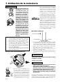
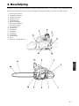
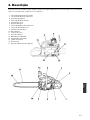
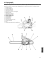
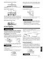
3. Description
Since this manual covers several models, there may be some difference between pictures and your unit.
Use the instructions that apply to your unit.
1. Throttle trigger
2. Safety trigger
3. Ignition switch
4. Oil tank cap
5. Recoil starter
6. Front handle
7. Fuel tank cap
8. Decompression valve
9. Airfilter cover
10. Guide bar
11. Saw chain
12. Chain brake
13. Choke knob
14. Spiked bumper
15. Chain catcher
16. Side case
17. Guide bar clamp nut

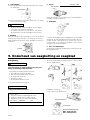
GB-8
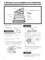
Power unit
Bar protector
Guide bar
Saw chain
Plug wrench
Screwdriver for
carburetor adjustment
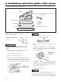
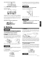
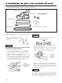
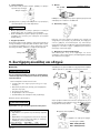
NOTE
Pay attention to the correct direction of the saw chain.
5. Fit the chain cover to the power unit and fasten the
nuts to finger tightness.
6. While holding up the tip of the bar, adjust the chain
tension by turning the tensioner screw until the tie
straps just touch the bottom side of the bar rail.
7. Tighten the nuts securely with the bar tip held up
(12 ~ 15 N·m). Then check the chain for smooth ro-
tation and proper tension while moving it by hand. If
necessary, readjust with the chain cover loose.
8. Tighten the tensioner screw.
NOTE
A new chain will expand its length in the beginning of
use. Check and readjust the tension frequently as a loose
chain can easily derail or cause rapid wear of itself and
the guide bar.
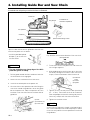
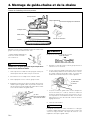
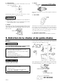
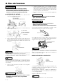
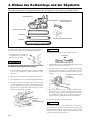
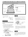
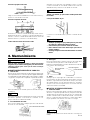
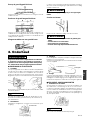
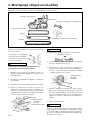
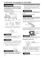
4. Installing Guide Bar and Saw Chain
A standard saw unit package contains the items as illustrated.
Open the box and install the guide bar and the saw
chain on the power unit as follows:
* Install the provided spiked
bumper (1) to the unit with
the two screws.
WARNING
• The saw chain has very sharp edges. Use thick
protective gloves for safety.
1. Pull the guard towards the front handle to check that
the chain brake is not engaged.
2. Loosen the nuts and remove the chain cover.
3. Install the attached spike to the power unit.
4. Gear the chain to the sprocket and, while fitting the
saw chain around the guide bar, mount the guide
bar to the power unit. Adjust the position of chain
tensioner nut on the chain cover to the lower hole of
guide bar.
(1) Tensioner
screw
(2) Loosen
(3) Tighten
(1) Hole
(2) Tensioner nut
(3) Chain cover
Spike and mountaing screws
Moving direction

G
B
GB-9
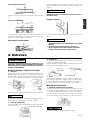
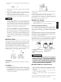
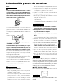
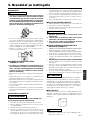
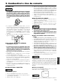
5. Fuel and Chain Oil
■ FUEL
WARNING
• Gasoline is very flammable. Avoid smoking or
bringing any flame or sparks near fuel. Make sure
to stop the engine and allow it cool before refuel-
ing the unit. Select outdoor bare ground for fuel-
ing and move at least 3 m (10 ft) away from the
fueling point before starting the engine.
agitate depending on oil ingredients, sufficient agi-
tation is necessary for the engine to last long. Be
careful that, if the agitation is insufficient, there is an
increased danger of early piston seizing due to ab-
normally lean mixture.
5.
Put a clear indication on the outside of the container
to avoid mixing up with gasoline or other containers.
6. Indicate the contents on outside of container for easy
identification.
■ FUELING THE UNIT
1. Untwist and remove the fuel cap. Rest the cap on a
dustless place.
2. Put fuel into the fuel tank to 80% of the full capacity.
3. Fasten the fuel cap securely and wipe up any fuel
spillage around the unit.
WARNING
1. Select flat and bare ground for fueling.
2. Move at least 10 feet (3 meters) away from the
fueling point before starting the engine.
3. Stop the engine before refueling the unit. At that
time, be sure to sufficiently agitate the mixed
gasoline in the container.
■ FOR YOUR ENGINE LIFE, AVOID:
1. FUEL WITH NO OIL (RAW GASOLINE) – It will cause
severe damage to the internal engine parts very
quickly.
2.
GASOHOL – It can cause deterioration of rubber and/
or plastic parts and disruption of engine lubrication.
3. OIL FOR 4-CYCLE ENGINE USE – It can cause spark
plug fouling, exhaust port blocking, or piston ring
sticking.
4. Mixed fuels which have been left unused for a
period of one month or more may clog the carbu-
retor and result in the engine failing to operate prop-
erly.
5. In the case of storing the product for a long period
of time, clean the fuel tank after rendering it empty.
Next, activate the engine and empty the carburetor
of the composite fuel.
6. In the case of scrapping the used mixed oil con-
tainer, scrap it only at an authorized repository site.
NOTE
As for details of quality assurance, read the description
in the section Limited Warranty carefully. Moreover, nor-
mal wear and change in product with no functional in-
fluence are not covered by the warranty. Also, be care-
ful that, if the usage in the instruction manual is not ob-
served as to the mixed gasoline, etc. described therein,
it may not be covered by the warranty.
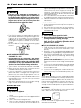
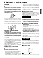
■ CHAIN OIL
Use motor oil SAE #10W-30 all year round or SAE
#30 ~ #40 in summer and SAE #20 in winter.
NOTE
Do not use wasted or regenerated oil that can cause
damage to the oil pump.
• The HITACHI engines are lubricated by oil specially
formulated for air-cooled 2-cycle gasoline engine use.
If genuine oil is not available, use an anti-oxidant
added quality oil expressly labeled for air-cooled 2-
cycle engine use(JASO FC GRADE OIL or ISO EGC
GRADE).
• Do not use BIA or TCW (2-stroke water-cooling type)
mixed oil.
■ RECOMMENDED MIXING RATIO
GASOLINE 50 : OIL 1
• Exhaust emission are controlled by the funda-
mental engine parameters and components (eq.,
carburation, ignition timing and port timing) with-
out addition of any major hardware or the intro-
duction of an inert material during combustion.
• These engines are certified to operate on unleaded
gasoline.
• Make sure to use gasoline with a minimum octane
number of 89RON (USA/Canada: 87AL).
• If you use a gasoline of a lower octane value than
prescribed, there is a danger that the engine tem-
perature may rise and an engine problem such as
piston seizing may consequently occur.
• Unleaded gasoline is recommended to reduce the
contamination of the air for the sake of your health
and the environment.
• Poor quality gasolines or oils may damage sealing
rings, fuel lines or fuel tank of the engine.
■ HOW TO MIX FUEL
WARNING
• Pay attention to agitation.
1. Measure out the quantities of gasoline and oil to be
mixed.
2. Put some of the gasoline into a clean, approved fuel
container.
3. Pour in all of the oil and agitate well.
4. Pour in the rest of gasoline and agitate again for at
least one minute. As some oils may be difficult to

GB-10
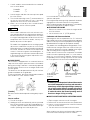
5. When you hear the engine want to start, with the
safety trigger pressed pull throttle trigger. This will
release the throttle from starting position to run po-
sition and will return the choke knob to run position
automatically.
6. Allow the engine to warm up with the throttle lever
pulled slightly.
WARNING
• Keep clear of the saw chain as it will start rotating
upon starting of engine.
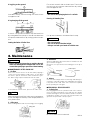
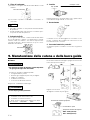
■ CHECKING THE OIL SUPPLY
WARNING
• Make sure to set up the bar and the chain when
checking the oil supply.
If not, the rotating parts may be exposed. It is very
dangerous.
After starting the engine, run the chain at medium speed
and see if chain oil is scattered off as shown in the figure.
The chain oil flow can be changed by inserting a screw-
driver in the hole on bottom of the clutch side. Adjust
according to your work conditions.
NOTE
The oil tank should become nearly empty by the time
fuel is used up. Be sure to refill the oil tank every time
when refueling the saw.
■ ADJUSTING THE CARBURETOR
The carburetor on your unit has been factory adjusted,
but may require fine tuning due to a change in operat-
ing conditions.
Before adjusting the carburetor, make sure that the pro-
vided air/fuel filters are clean and fresh and the fuel prop-
erly mixed.
When adjusting, take the following steps:
NOTE
Be sure to adjust the carburetor with the bar chain at-
tached.
WARNING
• It is very dangerous to run a chainsaw that mounts
broken parts or lacks any parts.
Before starting engine, make sure that all the parts
including bar and chain are installed properly.
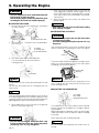
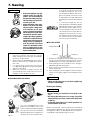
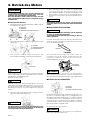
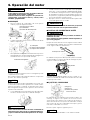
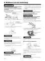
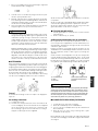
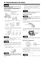
■ STARTING THE ENGINE
1. Fill fuel and chain oil tanks respectively, and tighten
the caps securely.
2. Set the switch to I position. Press the decompres-
sion valve (3).
3. Pull choke knob fully to choked position.
This will automatically lock the throttle in
starting position.
NOTE
If engine does not start easily, pull choke knob fully and
return it.
This will lock the throttle lever in starting position. Pull
recoil starter.
NOTE
Once the choke knob has been pulled out, it will not return
to the operating position even if you press down on it with
your finger. When you wish to return the choke knob to the
operating position, pull out the throttle lever instead.
4. While holding the saw unit securely on the ground,
pull the starter rope vigorously.
WARNING
• Do not start the engine while the chain saw
hangs in one hand. The saw chain may touch
your body. This in very dangerous.
6. Operating the Engine
(1) Chain oil
(2) Fuel
(3) Decompression valve
(1) Switch
(2) Throttle lever
(3) Throttle interlock
Chain oil
Chain oil flow
adjusting
(1) L needle
(2) H needle
(3) Idle adjusting screw
MAX
MIN
Choke knob

G
B
GB-11
In case the brake is not effective, ask our dealer for in-
spection and repairs.
If the engine keeps rotating at high speed with the brake
engaged, the clutch will overheat causing trouble.
When the brake engages during operation, immediately
release the throttle lever to stop the engine.
■ STOPPING THE ENGINE
1. Release the throttle lever to allow the engine to idle
for a few minutes.
2. Set the switch to the “O” (STOP) position.
Carburetor anti-freeze mechanism
Operating chain saws in temperatures of 0 – 5°C at times of
high humidity may result in ice forming within the carburetor,
and this in turn may cause the output power of the engine to
be reduced or for the engine to fail to operate smoothly.
This product has accordingly been designed with a ven-
tilation hatch on the right side of the surface of the cylin-
der cover to allow warm air to be supplied to the engine
and to thereby prevent icing from occurring.
Under normal circumstances the product should be
used in the normal operating mode, i.e., in the mode to
which it is set at the time of shipment. However when
the possibility exists that icing may occur, the unit should
be set to operate in the anti-freeze mode before use.
WARNING
• Continuing to use the product in the anti-freeze mode
even when temperatures have risen and returned to
normal, may result in the engine failing to start prop-
erly or in the engine failing to operate at its normal
speed, and for this reason you should always be sure
to return the unit to the normal operating mode if
there is no danger of icing occurring.
■ HOW TO SWITCH BETWEEN OPERATING MODES
1. Flip the engine switch to turn off the engine.
2. Remove the air cleaner cover from the cylinder cover
3. Loosen a screw and remove the screen on the back
of the air cleaner cover.
4. Turn the screen a half and reinstall to the cover.
When using the saw with the anti-freeze mode, frequently
check the screen and keep it clean of saw dust.
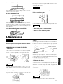
1. H and L needles are restricted within the number of
turn as shown below.
H needle : -
1
/
4
L needle : -
1
/
4
2. Start the engine and allow it to warm up in low speed
for a few minutes.
3. Turn the idle adjusting screw (T) counterclockwise
so that the saw chain does not turn. If the idling
speed is too slow, turn the screw clockwise.
4. Make a test cut and adjust the H needle for best
cutting power, not for maximum speed.
NOTE
Some models sold areas with strict exhaust emis-
sion regulation do not have high and low speed car-
buretor adjustments. Such adjustments may allow
the engine to be operated outside of their emission
compliance limits. For these models, the only car-
buretor adjustment is idle speed.
For models that equipped with low and high speed
adjustments; carburetors are pre set at the factory
Minor adjustments may optimize performance based
on climate, altitude, etc. Never turn the adjustment
screws in increments greater than 90 degrees, as
engine damage can result from incorrect adjustment
If you are not familiar with type of adjustment-assis-
tance HITACHI dealer.
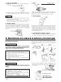
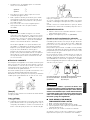
■ CHAIN BRAKE
This machine is equipped with an automatic brake to
stop saw chain rotation upon occurrence of kickback
during saw cutting. The brake is automatically operated
by inertial force, which acts on the weight fitted inside
the front guard.
This brake can also be operated manually with the front
guard turned down to the guide bar.
To release the brake, pull up the front guard toward the
front handle till a “click” sound is heard.
[Caution]
Be sure to confirm brake operation during daily inspec-
tion.
How to confirm:
1) Turn off the engine.
2) Holding the chain saw horizontally, release your hand
from the front handle, hit the tip of the guide bar to a
stump or a piece of wood, and confirm brake op-
eration. Operating level varies by bar size.
(4) Normal operating mode
(5) Anti-freeze mode
(6) Screen
(1) Air cleaner cover
(2) Shutter plate
(3) Screw

GB-12
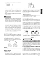
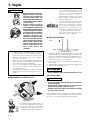
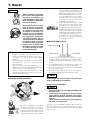
7. Sawing
• Before proceeding to your job,
read the section “For Safe Op-
eration”. It is recommended to
first practice sawing easy logs.
This also helps you get accus-
tomed to your unit.
• Always follow the safety regu-
lations. The chain saw must
only be used for cutting wood.
It is forbidden to cut other
types of material. Vibrations
and kickback vary with differ-
ent materials and the require-
ments of the safety regulations
would not be respected. Do not
use the chain saw as a lever for
lifting, moving or splitting ob-
jects. Do not lock it over fixed
stands. It is forbidden to hitch
tools or applications to the
PTO other than those specified
by the manufacturer.
• When completing a cut, be ready to hold up
the unit as it breaks into clear, so it will not
follow through and cut your legs, feet or body,
or contact an obstruction.
• Always keep the spiked bumper face to a tree,
because the chain may suddenly be drawn
into a tree.
• It is not necessary to force the saw into the
cut. Apply only light pressure while running the
engine at full throttle.
• When the saw chain is caught in the cut, do
not attempt to pull it out by force, but use a
wedge or a lever to open the way.
■ GUARD AGAINST KICKBACK
• This saw is equipped with a chain
brake that will stop the chain in the
event of kickback if operating prop-
erly. You must check the chain brake
operation before each usage by run-
ning the saw at full the throttle for I -
2 seconds and pushing the front
hand guard forward. The chain
should stop immediately with the en-
gine at full speed. If the chain is slow
to stop or does not stop, replace the
brake band and clutch drum before
use.
• It is extremely important that the
chain brake be checked for proper
operation before each use and that
the chain be sharp in order to main-
tain the kickback safety level of this
saw. Removal of the safety devices,
inadequate maintenance, or incor-
rect replacement of the bar or chain
may increase the risk to serious per-
sonal injury due to kickback.
■ FELLING A TREE
1. Decide the felling direction considering the wind,
lean of the tree, location of heavy branches, ease of
completing the task after felling and other factors.
2. While clearing the area around the tree, arrange a
good foothold and retreat path.
3. Make a notch cut one-third of the way into the tree
on the felling side.
4. Make a felling cut from the opposite side of the notch
and at a level slightly higher than the bottom of the
notch.
WARNING
• When you fell a tree, be sure to warn neighboring
workers of the danger.
Bucking and Limbing
WARNING
• Always ensure your foothold. Do not stand on the
log.
• Be alert to the rolling over of a cut log. Especially
when working on a slope, stand on the uphill side
of the log.
• Follow the instructions in “For Safe Operation” to
avoid kickback of the saw.
Before starting work, check the direction of bending
force inside the log to be cut. Always finish cutting from
the opposite side of the bending direction to prevent
the guide bar from being caught in the cut.
Notch cut
Felling cut
Felling direction
WARNING

G
B
GB-13
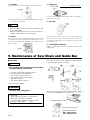
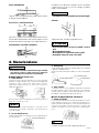
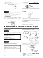
8. Maintenance
Oiling port
Grease port
Sprocket
Oiling port
A log lying on the ground
Saw down halfway, then roll the log over and cut from
the opposite side.
A log hanging off the ground
In area A, saw up from the bottom one-third and finish
by sawing down from the top. In area B, saw down from
the top one-third and finish by sawing up from the bot-
tom.
Cutting the limbs of Fallen Tree
First check to which side the limb is bent. Then make
the initial cut from the bent side and finish by sawing
from the opposite side.
WARNING
• Be alert to the springing back of a cut limb.
Pruning of Standing Tree
Cut up from the bottom, finish down from the top.
WARNING
• Do not overreach.
• Do not cut above shoulder height.
• Always use both your hands to hold the saw.
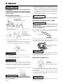
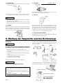
3. Guide bar
When the guide bar is dismounted, remove sawdust in the bar
groove and the oiling port.
Grease the nose sprocket from the feeding port on the tip of
the bar.
4. Others
Check for fuel leakage and loose fastenings and damage to
major parts, especially handle joints and guide bar mounting.
If any defects are found, make sure to have them repaired
before operating the saw again.
■ PERIODICAL SERVICE POINTS
1. Cylinder fins
Dust clogging between the cylinder fins will cause overheat-
ing of the engine. Periodically check and clean the cylinder
fins after removing the air cleaner and the cylinder cover. When
installing the cylinder cover, make sure that switch wires and
grommets are positioned correctly in place.
NOTE
Be sure to block the air intake hole.
WARNING
• Before cleaning, the inspecting or repairing the unit,
make sure that engine has stopped and is cool. Dis-
connect the spark plug to prevent accidental starting.
■ MAINTENANCE AFTER EACH USE
1. Air filter
Dust on the cleaner surface can be removed by tapping a
corner of the cleaner against a hard surface. To clean dirt in
the meshes, split the cleaner into halves and brush in gaso-
line. When using compressed air, blow from the inside.
To assemble the cleaner halves, press the rim until it clicks.
NOTE
When installing the main filter, make sure that the grooves
on the filter edge are correctly fit with the projections on
the cylinder cover.
2. Oiling port
Dismount the guide bar and check the oiling port for clogging.

GB-14
Place the file on the cutter and push straight forward.
Keep the file position as illustrated.
After each cutter has been filed, check the depth gauge
and file it to the proper level as illustrated.
4. Spark plug
Clean the electrodes with a wire brush and reset the gap to
0.65 mm as necessary.
5. Sprocket
Check for cracks and for excessive wear interfering with the
chain drive. If the wear is considerable, replace it with new
one. Never fit a new chain on a worn sprocket, or a worn chain
on a new sprocket.
6. Front and Rear dampers
Replace if adhered part is peeled or crack is observed on the
rubber part.
2. Fuel filter
(a) Using a wire hook, take out the filter from the filler port.
(b) Disassemble the filter and wash with gasoline, or replace
with a new one if needed.
NOTE
• After removing the filter, use a pinch to hold the end
of the suction pipe.
• When assembling the filter, take care not to allow fil-
ter fibers or dust inside the suction pipe.
3. Oil tank
With a wire hook, take out the oil filter through the filler port and
clean in gasoline. When putting the filter back into the tank,
make sure that it comes to the front right corner. Also clean off
dirt in the tank.
Fuel filter
9. Maintenance of Saw Chain and Guide Bar
Appropriate gauge checker
Champion NGK
CS40EM/45EM RCJ-6Y BPMR8Y
Depth gauge standard
21BP: .025
″″
″″
″ (0.64 mm)
33SL: .020
″″
″″
″ (0.51 mm)
Make the shoulder round
Oil filter
0.6 ~ 0.7 mm
■ Saw Chain
WARNING
• It is very important for smooth and safe operation
to always keep the cutters sharp.
The cutters need to be sharpened when:
• Sawdust becomes powder-like.
• You need extra force to saw in.
• The cut path does not go straight.
• Vibration increases.
• Fuel consumption increases.
Cutter setting standards:
WARNING
• Be sure to wear safety gloves.
Before filing:
• Make sure the saw chain is held securely.
• Make sure the engine is stopped.
• Use a round file of proper size for the chain.
Chain type: 21BP/20BP 33SL
File size: 3/16 in (4.76 mm) 5/32 in (3.97 mm)

G
B
GB-15
WARNING
• This saw is equipped with one of the following low
kickback bar/chain combinations:
HITACHI Part Number
Bar Size Guide Bar Saw Chain
16 107-72811-200 138-32625-20(21BP-66E)
18 105-72830-201 136-32578-20(21BP-72E)
• The bar rail should always be square. Check for wear
of the bar rail. Apply a ruler to the bar and the out-
side of a cutter. If a gap is observed between them,
the rail is normal. Otherwise, the bar rail is worn.
Such a bar needs to be corrected or replaced.
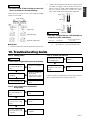
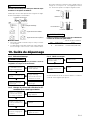
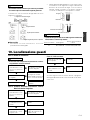
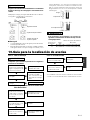
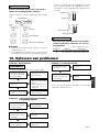
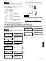
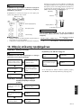
10. Troubleshooting Guide
Case 1. Starting failure
WARNING
• Make sure the icing prevention system is not working.
Check fuel for water
or substandard mix-
ture.
Replace with proper
fuel.
Check for engine
flooding.
Check spark ignition.
Remove and dry the
spark plug.
Then pull the starter
again with no choke.
Replace with a new
plug.
Case 2. Lack of power/Poor acceleration/
Rough idling
Case 3. Oil does not come out
Check fuel for water
or substandard mix-
ture.
Check air filter and
fuel filter for clog-
ging.
Check carburetor
for inadequate ad-
justment.
If the unit seems to need further service, please consult
with an authorized service shop in your area.
Replace with proper
fuel.
Clean.
Readjust speed
needles.
Check oil for sub-
standard quality.
Check oil passage
and ports for clog-
ging.
Replace.
Clean.
a
d
d
a
a
d
d
a
a
a
d
a
a
WARNING
• Be sure to round off the front edge to reduce the
chance of kickback or tie-strap breakage.
Make sure every cutter has the same length and edge
angles as illustrated.
■ Guide Bar
• Reverse the bar occasionally to prevent partial wear.
Cutter length
Filing angle
Side plate angle
Top plate cutting angle
Ruler
Gap
No gap
Chain tilts

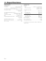
GB-16
11. Specifications
Power unit:
Displacement (cm
3
): ............................................. 49.3
Fuel: ................ Mixture (Gasoline 50 : Two-cycle oil 1)
Fuel tank capacity (cm
3
): ....................................... 550
Chain oil: ................................. Motor oil SAE# 10W-30
Oil tank capacity (cm
3
):.......................................... 260
Carburetor: ..................... Diaphragm type (Walbro WT)
ignition system: .....................................Pointless (CDl)
Spark plug:......................................Champion RCJ-6Y
Oil feeding system: ...... Automatic pump with adjuster
Sprocket (Teeth x Pitch): ............................ 7T x 0.325
″
Dimensions (L x W x H) (mm): ............ 410 x 235 x 265
Dry weight (kg): .................................................... 4.90
Cutting head:
Guide bar
Type: ................................................ Sprocket nose
Size (in. (mm)): ........................... CS40EM 16 (400)
CS45EM 18 (450)
Saw chain
Type: .................................................. Oregon 21BP
Pitch (in. (mm)):.................................... 0.325 (8.26)
Gauge (in. (mm)):................................. 0.058 (1.47)
Type: .................................................. Oregon 33SL
Pitch (in. (mm)):.................................... 0.325 (8.26)
Gauge (in. (mm)):................................. 0.050 (1.27)
Power (kw/min
-1
) ........................................ 2.51/10,000
Max speed (min
-1
) ............................................. 13,000
Idle speed (min
-1
) ................................................ 2,500
Specifications are subject to change without notice.

F
R
FR-1
CS40EM/45EM
MODE D’EMPLOI
TRONÇONNEUSES
Lire attentivement le manuel avant
d’utiliser la machine.

FR-2
EXPLICATION DES SYMBOLES ET REGLES DE SECURITE
Lire attentivement le manuel
avant d’utiliser la machine.
Porter casque,
lunettes de protection
et protège-oreilles.
Utiliser la
tronçonneuse en
se servant des
deux mains.
Avertissement !
Phénomène de rebond
dangereux.
Lisez, cherchez à
comprendre et suivez
toutes les instructions.
AVERTISSEMENT !!!
DANGER D’ATTEINTE A L’OUIE
L’OPERATEUR UTILISANT NORMALEMENT CETTE
MACHINE PEUT S’EXPOSER QUOTIDIENNEMENT
A UN BRUIT EGAL OU DEPASSANT
85 dB(A)
MODELE
CS40EM 49,3 cm
3
/45EM
NIVEAU SONORE
NIVEAU DE VIBRATION
ISO 22868
LpA
ISO 22868
Lw mesuré
2000/14/EC
LwA
103,6 dB(A)
110 dB(A)
ISO 22867
100,8 dB(A)
Poignée
avant
Poignée
arriére
5,5 m/s
2
7,2 m/s
2

F
R
FR-3
Sommaire
1. Pour la sécurité ..................................................................................... 4
2. Explication des symboles figurant sur la machine................................ 6
3. Description ............................................................................................ 7
4. Montage du guide-chaîne et de la chaîne ............................................ 8
5. Carburant et huile de chaîne ................................................................ 9
6. Moteur ..................................................................................................10
7. Travail à la tronçonneuse .................................................................... 12
8. Entretien .............................................................................................. 13
9. Entretien de la chaîne et du guide-chaîne .......................................... 14
10. Guide de dépannage .......................................................................... 15
11. Fiche technique .................................................................................. 16
Yoshio Osada
Direeteur
Signed in Chiba, Japan
DECLARATION DE CONFORMITE ”
(Directive 98/37/EC, EMC 89/336/EEC)
et aux réglementations prises pour sa
transposition Côntrole de production interne
LE FABRICANT : Nikko Tanaka Engineering Co., Ltd
3-4-29 Tsudanuma
Narasino
Chiba, Japan
DECLARE QUE LE MODELE DE LA MACHINE DESIGNEE CI – DESSOUS:
Désignation : CS40EM/45EM
Nº de série. : E57001 et suivants
Marque : Nikko Tanaka Engineering
EST CONFORME AUX DISPOSITION DE LA DIRECTIVE “MACHINE”
MODIFIEE (Directive 98/37/EC, EMC 89/336/EEC) ET AUX LEGISLATIONS
NATIONALES LA TRANSPOSANT A L’ETRANGER (ISO 11681-1, ISO 12100-
1 et -2, CISPR 12): et
A OBTENU UNE ATTESTATION DE TYPE “CE” N° 404/05/1070 PAR 404,
SMP SVENSK MASKINPROVNINGAB, FYRISBORGSGAIAN 3, SE-754 50,
Uppsala, Suède.
05/01/2007
Seite wird geladen ...
Seite wird geladen ...
Seite wird geladen ...
Seite wird geladen ...
Seite wird geladen ...
Seite wird geladen ...
Seite wird geladen ...
Seite wird geladen ...
Seite wird geladen ...
Seite wird geladen ...
Seite wird geladen ...
Seite wird geladen ...
Seite wird geladen ...
Seite wird geladen ...
Seite wird geladen ...
Seite wird geladen ...
Seite wird geladen ...
Seite wird geladen ...
Seite wird geladen ...
Seite wird geladen ...
Seite wird geladen ...
Seite wird geladen ...
Seite wird geladen ...
Seite wird geladen ...
Seite wird geladen ...
Seite wird geladen ...
Seite wird geladen ...
Seite wird geladen ...
Seite wird geladen ...
Seite wird geladen ...
Seite wird geladen ...
Seite wird geladen ...
Seite wird geladen ...
Seite wird geladen ...
Seite wird geladen ...
Seite wird geladen ...
Seite wird geladen ...
Seite wird geladen ...
Seite wird geladen ...
Seite wird geladen ...
Seite wird geladen ...
Seite wird geladen ...
Seite wird geladen ...
Seite wird geladen ...
Seite wird geladen ...
Seite wird geladen ...
Seite wird geladen ...
Seite wird geladen ...
Seite wird geladen ...
Seite wird geladen ...
Seite wird geladen ...
Seite wird geladen ...
Seite wird geladen ...
Seite wird geladen ...
Seite wird geladen ...
Seite wird geladen ...
Seite wird geladen ...
Seite wird geladen ...
Seite wird geladen ...
Seite wird geladen ...
Seite wird geladen ...
Seite wird geladen ...
Seite wird geladen ...
Seite wird geladen ...
Seite wird geladen ...
Seite wird geladen ...
Seite wird geladen ...
Seite wird geladen ...
Seite wird geladen ...
Seite wird geladen ...
Seite wird geladen ...
Seite wird geladen ...
Seite wird geladen ...
Seite wird geladen ...
Seite wird geladen ...
Seite wird geladen ...
Seite wird geladen ...
Seite wird geladen ...
Seite wird geladen ...
Seite wird geladen ...
Seite wird geladen ...
Seite wird geladen ...
Seite wird geladen ...
Seite wird geladen ...
Seite wird geladen ...
Seite wird geladen ...
Seite wird geladen ...
Seite wird geladen ...
Seite wird geladen ...
Seite wird geladen ...
Seite wird geladen ...
Seite wird geladen ...
Seite wird geladen ...
Seite wird geladen ...
Seite wird geladen ...
Seite wird geladen ...
Seite wird geladen ...
Seite wird geladen ...
Seite wird geladen ...
Seite wird geladen ...
Seite wird geladen ...
Seite wird geladen ...
Seite wird geladen ...
Seite wird geladen ...
Seite wird geladen ...
Seite wird geladen ...
Seite wird geladen ...
Seite wird geladen ...
Seite wird geladen ...
Seite wird geladen ...
-
 1
1
-
 2
2
-
 3
3
-
 4
4
-
 5
5
-
 6
6
-
 7
7
-
 8
8
-
 9
9
-
 10
10
-
 11
11
-
 12
12
-
 13
13
-
 14
14
-
 15
15
-
 16
16
-
 17
17
-
 18
18
-
 19
19
-
 20
20
-
 21
21
-
 22
22
-
 23
23
-
 24
24
-
 25
25
-
 26
26
-
 27
27
-
 28
28
-
 29
29
-
 30
30
-
 31
31
-
 32
32
-
 33
33
-
 34
34
-
 35
35
-
 36
36
-
 37
37
-
 38
38
-
 39
39
-
 40
40
-
 41
41
-
 42
42
-
 43
43
-
 44
44
-
 45
45
-
 46
46
-
 47
47
-
 48
48
-
 49
49
-
 50
50
-
 51
51
-
 52
52
-
 53
53
-
 54
54
-
 55
55
-
 56
56
-
 57
57
-
 58
58
-
 59
59
-
 60
60
-
 61
61
-
 62
62
-
 63
63
-
 64
64
-
 65
65
-
 66
66
-
 67
67
-
 68
68
-
 69
69
-
 70
70
-
 71
71
-
 72
72
-
 73
73
-
 74
74
-
 75
75
-
 76
76
-
 77
77
-
 78
78
-
 79
79
-
 80
80
-
 81
81
-
 82
82
-
 83
83
-
 84
84
-
 85
85
-
 86
86
-
 87
87
-
 88
88
-
 89
89
-
 90
90
-
 91
91
-
 92
92
-
 93
93
-
 94
94
-
 95
95
-
 96
96
-
 97
97
-
 98
98
-
 99
99
-
 100
100
-
 101
101
-
 102
102
-
 103
103
-
 104
104
-
 105
105
-
 106
106
-
 107
107
-
 108
108
-
 109
109
-
 110
110
-
 111
111
-
 112
112
-
 113
113
-
 114
114
-
 115
115
-
 116
116
-
 117
117
-
 118
118
-
 119
119
-
 120
120
-
 121
121
-
 122
122
-
 123
123
-
 124
124
-
 125
125
-
 126
126
-
 127
127
-
 128
128
-
 129
129
-
 130
130


Hitachi CS40EM Bedienungsanleitung
- Kategorie
- Kraftkettensägen
- Typ
- Bedienungsanleitung
- Dieses Handbuch eignet sich auch für
in anderen Sprachen
- English: Hitachi CS40EM Owner's manual
- français: Hitachi CS40EM Le manuel du propriétaire
- español: Hitachi CS40EM El manual del propietario
- italiano: Hitachi CS40EM Manuale del proprietario
- Nederlands: Hitachi CS40EM de handleiding
- português: Hitachi CS40EM Manual do proprietário
Verwandte Artikel
Andere Dokumente
-
McCulloch Mac20X Bedienungsanleitung
-
Jonsered 380 Bedienungsanleitung
-
MC CULLOCH CS330 Bedienungsanleitung
-
 IKRA Mogatec PC 26 TL Operating Instructions Manual
-
McCulloch CS 370 Bedienungsanleitung
-
Zenoah G621AVS Bedienungsanleitung
-
Ikra PCS 3835 Bedienungsanleitung
-
-
Husqvarna 50 Bedienungsanleitung
-
