Sachtler FSB 10 Benutzerhandbuch
- Kategorie
- Stative
- Typ
- Benutzerhandbuch

FSB 10 Fluid Head
User Guide
FSB 10 Fluid Head
Part No. S2045-0001
S2046-0001
EN DE
www.sachtler.com

Copyright © 2016
All rights reserved.
Original Instructions: English
All rights reserved throughout the world. No part of this publication may be stored in a retrieval system, transmitted, copied or reproduced in any
way, including, but not limited to, photocopy, photograph, magnetic or other record without the prior agreement and permission in writing of the Vitec
Group Plc.
Disclaimer
The information contained in this publication is believed to be correct at the time of printing. Vitec Videocom Ltd reserves the right to make changes
of the publication.
Should this publication not contain information on the core functionality of your product, please let us know. You may be able to access the latest
revision of this publication from our website.
Trademarks
All product trademarks and registered trademarks are the property of The Vitec Group Plc.
All other trademarks and registered trademarks are the property of their respective companies.
Published by:
Vitec Videocom Ltd
Email: [email protected]

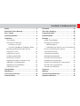
Contents / Inhaltverzeichnis
Safety.....................................2
About this Guide / Warranty
..................4
Box Contents
..............................5
Operating Elements
. . . . . . . . . . . . . . . . . . . . . . . . . 6
Installation.................................8
Touch Bubble
.............................8
Mounting the Fluid Head
....................8
Mounting to a Tripod
.....................8
...9
.......10
Fitting the Pan Bar
........................14
Adjusting the Pan Bar
.....................14
...................15
Balancing the Payload
.....................16
.......16
...............18
...............18
Adjusting the Drags
.......................20
Transportation
............................21
Maintenance
..............................22
Technical Specication
.....................23
General Notices
...........................24
Sicherheit ................................26
Über diese Anleitung
.......................28
Verpackungsinhalt
. . . . . . . . . . . . . . . . . . . . . . . . . 29
Bedienelemente
...........................30
Montage..................................32
.....................32
Montage des Fluidkopfes
..................32
Stativbefestigung
......................32
Umwandlung des Kopfes in einen Flachboden 33
Einsatz und Entnahme der Kamera
..........34
Schwenkarmmontage
.....................38
Schwenkarmverstellung
...................38
..................39
Einstellen der Kamerabalance
..............40
Einstellen des Schwerpunktes . . . . . . . . . . . . . . . 40
Zusätzliche Einstellung des Schwerpunktes
...42
Einstellen des Gegengewichts
..............42
Einstellen der Dämpfung
...................44
Transport.................................45
Wartung..................................46
Technische Spezikationen..................47
Allgemeine Hinweise
.......................48

2
Safety
Important information on the safe installation and operation of
this product. Read this information before operating the product.
For your personal safety, read these instructions.
Do not operate the product if you do not understand how to use
it safely.
Save these instructions for future reference.
Warning Symbols Used in these Instructions
Safety cautions are included in these instructions. These safety
instructions must be followed to avoid possible personal injury and
avoid possible damage to the product.
!
WARNING!
Where there is a risk of personal injury or injury to
others, comments appear supported by the word
‘WARNING’.
Health and Safety
!
WARNING! Risk of personal injury or injury to others. All
personnel must be fully trained and adhere to correct manual
handling techniques and Health & Safety regulations. It is the
responsibility of the local organisation to enforce safe working
practices at all times.
Mounting and Installation
!
WARNING! Do not
the combined mass of the head and its full payload.
!
WARNING! Risk of nger entrapment. Do not
!
CAUTION! Always lock the horizontal and vertical brakes when
head on the tripod.
!
CAUTION! Hold the camera securely when mounting or
adjustments to the tripod height or footprint.
!
CAUTION! Always hold the pan bar when making adjustments
to the counterbalance or camera position. Do not use the pan
!
CAUTION! Do not attach heavy items to the pan bar.
!
CAUTION! Always remove the camera before transporting.
!
CAUTION!
Where there is a risk of damage to the product,
associated equpment, process or surroundings,
comments appear supported by the word ‘CAUTION’.

3
Safety
Maintenance
!
WARNING!
effect the safety of the product. It may also invalidate the
terms and conditions of the product warranty.
!
CAUTION! When replacing the battery, only use the same or
an equivalent type of battery recommended for use with this
product.

4
About this Guide
smooth pan and tilt movement giving the operator total image control
through a wide range of angles.
This user guide has been produced to instruct the user on the correct
Intended Use
About this User Guide
Warranty
This product is covered by a one year warranty.
The warranty will be invalidated if:
• The head is improperly installed or used in a manner contrary to
this user guide.
• The head housing is opened by unauthorised personnel.
Extended Warranty
Please register at www.sachtler.com for an extended warranty
period.
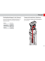
Serial Number Location
S2046 XXX XXXX

5
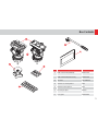
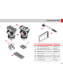
Box Contents
Item Description Part No
1
2 Tie down SKO12B0366
3 Touch & Go camera plate S 0364
4 Sideload camera plate S 0164
5 Pan bar plus right 0992SP
6 User guide
6
OR

6
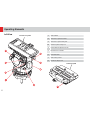
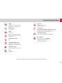
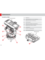
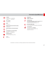
Operating Elements
1 Vertical brake
2 Touch & Go system lock lever
3 Touch & Go system safety lock
3a Sideload system safety lock
4
5 Illuminated touch bubble
6 Horizontal brake
7 Vertical drag control
8 Rosette for left pan bar
Left View
Touch & Go System
3a
Sideload system

7
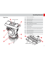
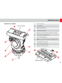
Operating Elements
1 Touch & Go camera plate S
1a Sideload camera plate S
2 Spare camera screws
2a Spare camera screws
3 Battery compartment for touch bubble
4 Horizontal drag control
5 Tie down mounting
6 Eyepiece leveller / accessory holder, attachment positions
7 Balance plate clamp knob
7a Balance plate clamp knob
8 Rosette for right pan bar
Right View
Touch & Go System
Sideload System
7a
2a
1a

8
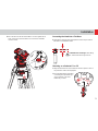
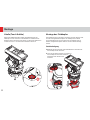
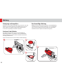
Installation
Mounting to a Tripod
1.
with one hand.
2.
the tie down loosely.
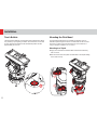
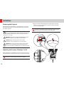
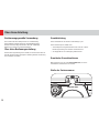
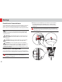
Touch Bubble
easy levelling in poor lighting conditions. The illumination is activated
approximately 20 seconds.
Mounting the Fluid Head
directly to a pedestal using the threaded holes in the ball base or
using an adaptor available as an accessory.

9
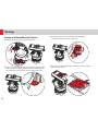
Installation
3. Move the head so that the level bubble is central. Tighten the tie
down, release the horizontal brake and check the level bubble
remains central.
Converting the Head Into a Flat Base
1.
lll
8 mm maximum
!
CAUTION! Risk of damage.
Pin, maximum thread length is 8 mm.
Mounting on a Pedestal Cl or Clll
1. Align the threaded holes in the ball base with the captive screws on
the pedestal or slider and fully tighten.
2.
or retracting the adjustable legs
on the pedestal so the level
bubble stays central.

10
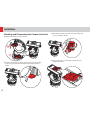
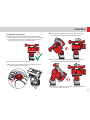
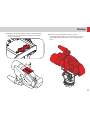
Installation
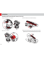
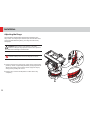
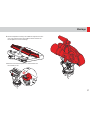
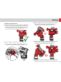
Mounting and Dismounting the Camera (S2046-1000)
1. Apply the horizontal and vertical brakes.
2. Hold the camera plate or camera with one hand. Grasp the locking
button.
3. With the safety button held down, move the locking lever
as far as possible to the left.
4. The camera plate or camera will be released from the
sliding balance plate.

11
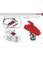
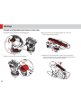
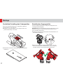
Installation
5. Attach the camera plate to the camera around its centre of gravity.
Additional screws are stored in the sliding balance plate assembly.
6. Mount the camera plate and camera onto the sliding balance plate.
It will lock automatically and the lock lever will click audibly back
into its initial position.

12
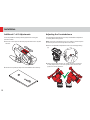
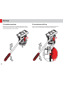
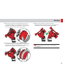
Installation
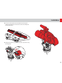
Mounting and Dismounting the Camera (S2045-1000)
1. Apply the horizontal and vertical brakes.
2. Release the clamp knob.
3.
4. Attach the camera plate to the camera around its centre of gravity,
observe the arrow on the plate indicating the direction of the arrow.
Additional screws are stored in the sliding balance plate assembly.
1
2

13
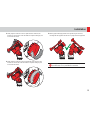
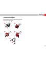
Installation
5. Place the camera plate into the dovetail and lower into place.
It will lock automatically and the lock lever will click audibly back
into its initial position.
6. Firmly lock the plate in position after the balance procedure using
the clamp knob.

14
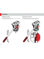
Installation
Fitting the Pan Bar
Fit and adjust the pan bar to the desired position, tighten the clamping
screw ensuring the teeth mesh fully.
Adjusting the Pan Bar
To adjust the position of the pan bar, loosen the clamping screw

15
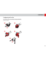
Installation
Conguring the Pan Bar
mounting, as follows:

16
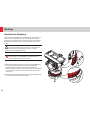
Installation
Balancing the Payload
and reliable operation.
!
WARNING! When balancing the payload, it is important to be
aware of the potential danger that an unbalanced payload will
balance is set correctly.
!
WARNING! Do not
!
CAUTION! Always hold the pan bar when making
adjustments to the counterbalance or camera position.
!
CAUTION! The camera, pan bars and all accessories must
head.
1.
drag to “0”. Set the counterbalance adjustment knob proportionate
.
Adjusting the Centre of Gravity (C of G)
of gravity. See “Mounting the Fluid Head” on page 8.
Moving the counterbalance from one setting to another requires
the head to pass the horizontal position to take affect.

17
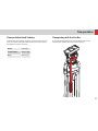
Installation
Counterbalance Adjustment
2.
Observe how the payload moves and where it stops.
3. If the payload falls away in either direction:
(a) Unlock the sliding balance plate by unscrewing the balance
plate adjuster on the balance plate.
(b)
(c)
(d)
are required, repeat steps 1 to 3.

18
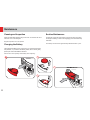
Installation
Additional C of G Adjustments
standard method:
1. Move the camera plate to offset the payload further in the required
direction.
2.
Adjusting the Counterbalance
accurately balance the payload.
Note, moving the counterbalance from one setting to another requires
the head to pass the horizontal position to take affect.
1.
2. Tilt the payload approximately 30° in both directions and release
it. If the payload stays in the same position when released, the
payload is correctly balanced.
Seite wird geladen ...
Seite wird geladen ...
Seite wird geladen ...
Seite wird geladen ...
Seite wird geladen ...
Seite wird geladen ...
Seite wird geladen ...
Seite wird geladen ...
Seite wird geladen ...
Seite wird geladen ...
Seite wird geladen ...
Seite wird geladen ...
Seite wird geladen ...
Seite wird geladen ...
Seite wird geladen ...
Seite wird geladen ...
Seite wird geladen ...
Seite wird geladen ...
Seite wird geladen ...
Seite wird geladen ...
Seite wird geladen ...
Seite wird geladen ...
Seite wird geladen ...
Seite wird geladen ...
Seite wird geladen ...
Seite wird geladen ...
Seite wird geladen ...
Seite wird geladen ...
Seite wird geladen ...
Seite wird geladen ...
Seite wird geladen ...
Seite wird geladen ...
-
 1
1
-
 2
2
-
 3
3
-
 4
4
-
 5
5
-
 6
6
-
 7
7
-
 8
8
-
 9
9
-
 10
10
-
 11
11
-
 12
12
-
 13
13
-
 14
14
-
 15
15
-
 16
16
-
 17
17
-
 18
18
-
 19
19
-
 20
20
-
 21
21
-
 22
22
-
 23
23
-
 24
24
-
 25
25
-
 26
26
-
 27
27
-
 28
28
-
 29
29
-
 30
30
-
 31
31
-
 32
32
-
 33
33
-
 34
34
-
 35
35
-
 36
36
-
 37
37
-
 38
38
-
 39
39
-
 40
40
-
 41
41
-
 42
42
-
 43
43
-
 44
44
-
 45
45
-
 46
46
-
 47
47
-
 48
48
-
 49
49
-
 50
50
-
 51
51
-
 52
52


Sachtler FSB 10 Benutzerhandbuch
- Kategorie
- Stative
- Typ
- Benutzerhandbuch
in anderen Sprachen
- English: Sachtler FSB 10 User manual
Verwandte Artikel
-
Sachtler FSB 4 Benutzerhandbuch
-
Sachtler Cine 30 HD Benutzerhandbuch
-
-
Sachtler Video 18 S2 Benutzerhandbuch
-
Sachtler video 18 S1 Benutzerhandbuch
-
Sachtler FSB 8 Manual Manual
-
-
-
-
Andere Dokumente
-
Vinten Vision blue5 Bedienungsanleitung
-
Vinten Vector 75 Operator Guide
-
Vinten Vision Blue 3 Bedienungsanleitung
-
-
-
Vinten Vector 750 Bedienungsanleitung
-
Vinten Vector 950 Bedienungsanleitung
-
-
ACE L MS CF 1011 Benutzerhandbuch
-