
Bedienungsanleitung
Manual
MAN_EL1002U
Version:
20211118
/ 13.12.2021
Freigabe:
T.W.
Seite 1 von 5
EL-100-2
Art.-Nr.: 0 4000 01 XX XX XX XX
eks Engel FOS GmbH & Co. KG
Schützenstraße 2-4
57482 Wenden-Hillmicke
Germany
Tel: +49 (0) 2762 9313-600
Fax: +49 (0) 2762 9313-7906
Internet: www.eks-engel.de
Rechtliche Hinweise
Legal Notice
Diese Anleitung enthält wichtige Anmerkungen und Warnungen, deren Nichtbe-
achtung zu ernsthaften Personen- oder Anlageschäden führen kann. Bitte lesen
Sie die Anleitung vor Inbetriebnahme der EL-100-2 Geräte aufmerksam durch.
Ordnungsgemäßer Transport, korrekte Lagerung und Installation sowie sorgfältige
Bedienung und Instandhaltung der EL-100-2 sind entscheidend für den sicheren
Betrieb.
This manual contains important notes and warnings. Their ignoration can cause
serious injuries or damages to the system. Please read the manual carefully
before using the equipment EL-100-2. Correct transport, proper storage and
installation as well as careful operation and maintenance of EL-100-2 are critical
for safe operation.

Bedienungsanleitung
Manual
MAN_EL1002U
Version:
20211118
/ 13.12.2021
Freigabe:
T.W.
Seite 2 von 5
Systembeschreibung
System description
Die Serie EL-100-2 sind 7-Port und 8-Port Unmanaged Industrial Ethernet
Layer 2 Switche. Sie zeichnen sich durch einfache Funktionalität und
Bedienfreundlichkeit wie Auto-Negotiation und Auto MDI/MDIX aus.
Die kompakte Bauform im industriellen Design zeichnet sich vor allem durch ihre
hohe Flexibilität bei der Konfiguration aus. So können bis zu 4 FX-Ports beliebig
bestückt werden. Als optische Anschlussvariante stehen neben ST und SC auch
E-2000® zur Verfügung. Alle Systeme können sowohl über zwei Fasern als auch
über eine Faser durch BIDI-Technik mit SC-Anschluss kommunizieren.
Als wichtige Leistungsmerkmale der Übertragung mit Kunststofffaser-, HCS,
Multimode- oder Singlemode-Lichtwellenleitern gelten die Unempfindlichkeit
gegenüber elektrischen und magnetischen Störungen, die Potenzialtrennung von
Sender und Empfänger sowie Reichweiten bis zu 40 km zwischen zwei LWL-
Systemen. LEDs und optional potenzialfreie Kontakte eines Fehlerrelais
signalisieren fehlerhafte Zustände.
Series EL-100-2 is 7-Port and 8-Port Unmanaged Industrial Ethernet Layer 2
Switches with Auto-Negotiation and Auto MDI/MDIX.
The rugged and compact housing allows a flexible FX-Port configuration. Up to 4
FX-Ports are available, each having a ST, SC or an E-2000® fiber optic
connector. All systems can communicate via two as well as one fiber with the help
of the BIDI-technology with SC port.
Important performance features of the transfer with POF, HCS, multimode or
singlemode fiber optic are the electromagnetic ruggedness, the potential
separation of transmitter and receiver, as well as ranges up to 40 km between two
fiber optic systems. LEDs and potential-free contacts (optional) of a fault detector
relay are able to signal defective states.
Anschlusshinweise
Hardware Installation
Achtung: Beim Betrieb elektrischer Betriebsmittel und Anlagen stehen zwangs-
läufig bestimmte Teile unter gefährlicher Spannung. Arbeiten an elektrischen
Anlagen oder Betriebsmitteln dürfen nur von einer Elektrofachkraft oder von
unterwiesenen Personen unter Anleitung und Aufsicht einer Elektrofachkraft,
den elektrotechnischen Regeln entsprechend, vorgenommen werden.
Schalten Sie die Systeme und Endgeräte spannungsfrei.
Rasten Sie das Gerät auf eine Tragschiene DIN EN auf, und überprüfen Sie den
sicheren Halt!
Achtung: Benutzen Sie nur die zugehörigen LWL-Anschlussstecker. Wir weisen
ausdrücklich daraufhin, dass der Anschluss mit falschen Steckverbinder
Schäden an den optischen Anschlüssen hervorrufen kann! Beachten Sie
zudem, dass die Stecker, die eine Verriegelung besitzen, nur in einer
definierten Position montiert werden können.
Achtung: Sehen Sie nicht in den optischen Sender! Das gebündelte und
abhängig von der Wellenlänge sichtbare oder unsichtbare Licht kann zu
Augenschäden führen!
Verbinden Sie den ankommenden Lichtwellenleiter mit dem optischen Empfänger
und den abgehenden LWL mit dem optischen Sender des LWL-System.
Benutzen Sie die beigefügten Stopfen, um Sender und Empfänger des LWL-
Systems im nicht eingebauten oder nicht benutzten Zustand vor Verunreini-
gungen oder Staub zu schützen.
Achtung: Knicken Sie das LWL-Kabel nicht zu stark und beachten Sie den
Biegeradius. Andernfalls kann das Kabel beschädigt werden und/oder die
Kommunikation zwischen den LWL-Wandlern nicht mehr gewährleistet werden.
Schalten Sie die Betriebsspannung für die LWL-Systeme ein. Zur Versorgung der
Systeme wird eine Betriebsspannung von 24 VDC benötigt, die an die
Klemmen VDC1 oder VDC2 und GND angelegt wird. VDC1 und VDC2 sind
redundante Versorgungsspannungseingänge mit Verpolungsschutz.
Achtung bei Systemen mit BIDI: Bei Verwendung von Systemen mit optischem
BIDI-Anschluss müssen immer die optischen Anschlüsse (Transceiver) vom
Typ A mit Typ B verbunden werden. Bei Systemen mit 2 FX-Ports ist der
optische Anschluss (Transceiver) mit dem Typ A immer der obere Anschluss.
Funktion der Status-LED´s:
VDC : +24 V Versorgungsspannung liegt an VDC1 oder VDC2
Link/Act : Datenverkehr
10/100 : leuchtet grün bei Datenverkehr mit 100 Mbit/s
Fehlerrelais (opt.):
An Klemmen K1 bis K3 befindet sich ein potentialfreier Fehlerrelaiskontakt; K2 ist
der gemeinsame Anschluss der Relais. Das Fehlerrelais fällt ab, wenn an den
VDC-Eingängen keine Versorgungsspannung anliegt.
Funktion der Kontakte K1 - K2: nicht belegt
Funktion der Kontakte K2 - K3: nicht belegt
Funktion des Kontakts K4: nicht belegt
Die Systeme verfügen über Auto-Negotiation und Auto MDI/MDIX.
Power off the devices, which will be connected.
Snap the system onto the DIN EN rail and check the correct holding!
Attention: Only use the correct optical connectors for the fiber optic system.
Using incorrect connectors can cause damage to the fiber optic system. Take
care that connectors with a latch can only be mounted in a defined position.
Attention: Don't stare into the optical cable or the transmitter of the fiber optic
system. Visible and non visible light (depending on its wavelength) of the optical
transmitter can cause eye-damages!
Connect the fiber optic system by using the correct fiber optic cable. Take care
that you always have to connect an optical transmitter and an optical receiver.
Use the plugs to save the unused optical receiver and transmitter against impurity.
Attention: Don't bend the fiber optic cable! Please refer to the specifications.
Otherwise the fiber optic cable can be damaged or the communication will be
disturbed.
Power on the devices. Please use a power supply of 24 VDC, connected to the
terminals marked with VDC1, VDC 2 and GND. Note that VDC 1 and VDC 2 are
redundant power inputs with reverse voltage protection.
Attention: BIDI Switches must always be connected from transceiver type A to a
transceiver type B. At switches with 2 FX-Ports always the upper one is the
transceiver type A.
Function of the Status-LEDs:
VDC : +24 V Power Supply at VDC1 or VDC2
Link/Act : data traffic
10/100 : lights green at 100 Mbit/s
Failure relay (optional):
There is a potential free failure relay contact at K1 – K3. K2 is the common
connector for the relays. The relay switches if there is no supply voltage at the
VDC inputs.
Function of K1 – K2: Not connected
Function of K2 – K3: Not connected
Function of K4: not connected
All switches features Auto-Negotiation und Auto MDI/MDIX..

Bedienungsanleitung
Manual
MAN_EL1002U
Version:
20211118
/ 13.12.2021
Freigabe:
T.W.
Seite 3 von 5
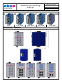
Ansicht / Views
8 TX
6 TX / 1 FX
6 TX / 2 FX
4 TX / 3 FX
2 TX / 4 FX
Anschlussbilder / Schematics

Bedienungsanleitung
Manual
MAN_EL1002U
Version:
20211118
/ 13.12.2021
Freigabe:
T.W.
Seite 4 von 5
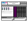
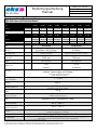
LWL-Anschlussvarianten / Fiber Optics Connectors Overview
Die Tabelle auf Seite 4 gibt nur einen Teil aller möglichen Artikelnummern wieder.
Nutzen Sie zusätzlich die Artikelnummern der Tabelle rechts. Weitere Systeme
auf Anfrage erhältlich.
Table on page 4 only shows a part of the possible article numbers. Please use
the table on the right side additionally. Please ask for additional articles.
ww / xx / yy / zz
Wellenlänge
Faser
Stecker
Reichweite
00
None
None
None
None
01
650
POF
ST
70 m
03
650
POF
SC
70 m
08
650
POF
Firecomms
70 m
09
650
POF
Klemm
70 m
11
850
HCS
ST
200 m
13
850
HCS
SC
200 m
15
850
HCS
E2000/0°
200 m
31
1300
Multimode
ST
5 km
33
1300
Multimode
SC
5 km
35
1300
Multimode
E2000/0°
5 km
36
1300/1550
Multimode
SC BIDI A
5 km
37
1550/1300
Multimode
SC BIDI B
5 km
51
1310
Singlemode
ST
30 km
53
1310
Singlemode
SC
30 km
55
1310
Singlemode
E2000/0°
30 km
56
1310/1550
Singlemode
SC BIDI A
30 km
61
1310
Singlemode
ST
60 km
63
1310
Singlemode
SC
60 km
66
1310
Singlemode
SC
100 km
76
1550/1310
Singlemode
SC BIDI B
30 km
Entsorgungshinweis
Disposal notes
Die Geräte dürfen nicht über den normalen Hausmüll entsorgt werden,
sondern können bei eks Engel FOS GmbH & Co. KG entsorgt werden.
The units must not be disposed with normal household waste but can
be returned to eks Engel FOS GmbH & Co. KG for disposal.

Bedienungsanleitung
Manual
MAN_EL1002U
Version:
20211118
/ 13.12.2021
Freigabe:
T.W.
Seite 5 von 5
Typenauswahl und Technische Daten*
Type Selection and Technical Data**
Typ EL-100-2
Type
8TX
6TX-1FX-
ST-MM
6TX-2FX-
ST-MM
4TX-3FX-
ST-MM
2TX-4FX-
ST-MM
6TX-1FX-
ST-SM
6TX-2FX-
ST-SM
4TX-3FX-
ST-SM
2TX-4FX-
ST-SM
Bestellnummer
Order No.
0 4000 01
00 00 00 00
0 4000 01
00 00 00 31
0 4000 01
00 00 31 31
0 4000 01
00 31 31 31
0 4000 01
31 31 31 31
0 4000 01
00 00 00 51
0 4000 01
00 00 51 51
0 4000 01
00 51 51 51
0 4000 01
51 51 51 51
100 FX ports
-
1 x ST
2 x ST
3 x ST
4 x ST
1 x ST
2 x ST
3 x ST
4 x ST
Typ EL-100-2
Type
8TX
6TX-1FX-
SC-MM
6TX-2FX-
SC-MM
4TX-3FX-
SC-MM
2TX-4FX-
SC-MM
6TX-1FX-
SC-SM
6TX-2FX-
SC-SM
4TX-3FX-
SC-SM
2TX-4FX-
SC-SM
Bestellnummer
Order No.
-
0 4000 01
00 00 00 33
0 4000 01
00 00 33 33
0 4000 01
00 33 33 33
0 4000 01
33 33 33 33
0 4000 01
00 00 00 53
0 4000 01
00 00 53 53
0 4000 01
00 53 53 53
0 4000 01
53 53 53 53
100 FX ports
-
1 x SC
2 x SC
3 x SC
4 x SC
1 x SC
2 x SC
3 x SC
4 x SC
Faserart
Fiber
-
Multimode
Singlemode
Fasertyp
Fiber type
-
50/125µm / 62,5/125µm
9/125µm
Faserspezifikation
Fiber specification
-
800 MHz*km / 500 MHz*km
Bandbreite / Bandwidth
3,5 ps/nm*km
Dispersionskoeffizient / Dispersion coeffcient
Wellenlänge
Wavelength
-
1300 nm
1310 nm
Budget
Budget
-
12 dB
3dB Systemreserve
16 dB
3dB Systemreserve
Distanzen max.
Distances max
-
5 km
(1 dB/km)
30 km
(0,3 dB/km)
Stromversorgung
Input power
12-30 VDC redundante Spannungsversorgung
(weitere Spannungen auf Anfrage)
12-30 VDC redundant power supply
(other voltages on request)
Leistungsverbrauch
Power consumption
5 – 6,4 W
Potentialtrennung
Insulation
500 V
Abmessungen B x H x T
Dimensions W x H x D
B: 60 mm, H: 120 mm, T: 110 mm
W: 60 mm, H: 120 mm, D: 110 mm
Gewicht
Weight
500 g
Gehäuse / Schutzart
Enclosure / IP-Code
Edelstahl, pulverbeschichtet / IP 20
Stainless steel, lacked / IP 20
MTBF
MTBF
900608,8116 h / 102,8092251 Jahre
Lagertemperatur
Storage temperature
-40 °C - +85 °C
Betriebstemperatur
Operation temperature
-10 °C - +50 °C
Feuchtigkeit
Humidity
Feuchtigkeit 5-95% RHD nicht kondensierend
Humidity 5-95% RHD non-condensing
EMV / EMC
EN61000-6-2 / EN55022 Class B +A1 + A2
LED Anzeige
LED indications
Systemfehler (rot) / Port LEDs (gelb/grün) / Stromversorgung (grün)
System failure (red) / Port LEDs (green/ yellow) / power supply (green)
* Sondertypen ergeben sich aus der Tabelle „ LWL-Anschlussvarianten“auf Seite 3
** Please refer for special solutions to table “Fiber Optics Connector Overview” on page 3
Technische Änderungen vorbehalten. Für Irrtümer und Druckfehler keine Haftung. © eks Engel FOS GmbH & Co. KG
Reserve technical changes. No liability is accepted for errors and printing errors. © eks Engel FOS GmbH & Co. KG
-
 1
1
-
 2
2
-
 3
3
-
 4
4
-
 5
5


in anderen Sprachen
- English: Eks EL-100-2 Owner's manual
Verwandte Artikel
-
Eks DL232-R Bedienungsanleitung
-
Eks DL-232MUX Benutzerhandbuch
-
-
-
-
-
-
-
-