
GB
FR
DE
ES
ASCO CONTROLS BV
P.O. Box 3, 3925 ZG Scherpenzeel, The Netherlands
Tel. +31(0)33 277 79 11 - Fax +31(0)33 277 45 61 / www.asconumatics.eu
DESCRIPTION
Series 307 are direct operated 3/2 AC-solenoid valves of the balanced
construction type with full flow capacity and screw type manual operator.
The solenoid valves have universal, normally closed or normally open operation.
The valve body is brass or stainless steel.
INSTALLATION
ASCO Numatics components are intended to be used only within the technical
characteristics as specified on the nameplate. Changes to the equipment
are only allowed after consulting the manufacturer or its representative.
Before installation depressurise the piping system and clean internally. The
equipment may be mounted in any position. Connect piping to valve according
to markings on valve body.
The pipe connections have to be in accordance with the size indicated on
the nameplate and fitted accordingly.
CAUTION:
• Reducingtheconnectionsmaycauseimproperoperationormalfunctioning.
• Fortheprotectionoftheequipmentinstallastrainerorltersuitablefor
the service involved in the inlet side as close to the product as possible.
• Iftape, paste,sprayora similarlubricantis used whentightening,
avoid particles entering the system.
• Useproper tools andlocate wrenches asclose aspossible tothe
connection point.
• Toavoiddamage to theequipment, DO NOT OVERTIGHTEN pipe
connections.
• Donotusevalveorsolenoidasalever.
• Thepipeconnectionsshouldnotapplyanyforce,torqueorstraintothe
product.
ELECTRICAL CONNECTION
In case of electrical connections, they are only to be made by trained person-
nel and have to be in accordance with the local regulations and standards.
CAUTION:
• Turnoffelectricalpowersupplyandde‑energisetheelectricalcircuit
and voltage carrying parts before starting work.
• Allelectricalscrewterminalsmustbeproperlytightenedaccordingto
the standards before putting into service.
• Dependentuponthevoltageelectricalcomponentsmustbeprovided
with an earth connection and satisfy local regulations and standards.
The equipment can have one of the following electrical terminals:
• SpadeplugconnectionsaccordingtoISO‑4400(whencorrectlyinstalled
this connection provides lP-65 protection).
• Embeddedscrewterminalsinmetalenclosurewith“Pg”cablegland.
• Flyingleadsorcables.
PUTTING INTO SERVICE
Before pressurising the system, first carry-out an electrical test. In case
of solenoid valves, energise the coil a few times and notice a muffled click
signifying the solenoid operation.
SERVICE
Most of the solenoid valves are equipped with coils for continuous duty
service. To prevent the possibility of personal or property damage do not
touch the solenoid which can become hot under normal operation conditions.
If the solenoid valve is easily accessible, the installer must provide protection
preventing accidental contact.
SOUND EMISSION
The emission of sound depends on the application, medium and nature of
the equipment used. The exact determination of the sound level can only be
carried out by the user having the valve installed in his system.
MAINTENANCE
Maintenance of ASCO Numatics products is dependent on service conditions.
Periodic cleaning is recommended, the timing of which will depend on the
mediaand service conditions.During servicing, componentsshould be
examined for excessive wear. A complete set of internal parts is available
as a spare parts kit. If a problem occurs during installation/maintenance or in
case of doubt please contact ASCO Numatics or authorised representatives.
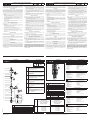
VALVE DISASSEMBLY
Disassembleinanorderlyfashion.Paycarefulattentiontoexplodedviews
provided for identification of parts.
1. Removeretaining clipand slipcoil off solenoidbase sub‑assembly.
CAUTION: when metal retaining clip disengages, it can spring upwards.
Removethespringwasher.
2. Unscrew solenoid base sub-assembly, remove its O-ring, and slip the
core with the core spring from the upper stem.
3. Unscrew the manual operator assembly and remove the manual operator
assembly and its O-rings, then remove the lower stem spring.
4. Insertasmallrodorasmallscrewdriverintothetransverseholeofthe
upper stem for extra grip and unscrew the lower stem from the upper stem.
5. Removetheupperstemdisc,thelowerstemdiscandthespacerfrom
betweentheupperandlowerstem.RemovethelowerstemO‑ring.
6. All parts are now accessible for cleaning or replacement.
VALVE REASSEMBLY
Reassemblein reverseorder ofdisassembly payingcareful attentionto
exploded views provided for identification and placement of parts.
1. NOTE:Lubricateallgaskets/O‑ringswithhighqualitysiliconegrease.
ReplacethemanualoperatorO‑ringsandthelowerstemO‑ring.
2. Replacetheupperstemdiscintheupperstemandreplacethelower
stem disc in the lower stem, then slip the spacer over the lower stem
and push the lower stem with the spacer into the underside of the valve
body.Applyloctite242sparinglytothelowerstemthreadandscrewthe
lower stem into the upper stem, torque the stem according to torque
chart.
3. Replacelowerstemspringandmanualoperatorassembly(option:rst
insert the manual operator assembly through the mounting bracket),
and torque manual operator assembly according to torque chart.
4. Slipthecoreovertheupperstemandreplacethecorespringintothe
core(placeclosedendontop).Lubricatetopcorefacewithalighthigh
grade machine oil.
5. Replace solenoidbase sub‑assemblyO‑ring andthe solenoid base
sub-assembly, and torque according to torque chart.
6. Install spring washer, coil and retaining clip.
7. After maintenance, operate the valve a few times to be sure of proper
operation.
MANUAL OPERATOR DISASSEMBLY
(Refertoexplodedview)
1. Driveouttherollpinwithasuitabledriftafterunscrewingthehousing
from valve body.
2. Removethestemandthespringfromthemanualoperatorhousing.
3. RemovetheO‑ringfromthemanualoperatorstem.
4. Allpartsarenowaccessibleforcleaningand/orreplacement.
MANUAL OPERATOR REASSEMBLY
Reassemblein reverseorder ofdisassembly payingcareful attentionto
explodedviewsprovidedforidenticationandplacementofparts.NOTE:For
stainless steel constructions it is highly advisable to use a suitable anti-seize
lubricant to avoid galling.
1. NOTE:Lubricateallgaskets/O‑ringswithhighqualitysiliconegrease.
ReplacetheO‑ringontothemanualoperatorstem.
2. Replacespringandstemintothemanualoperatorhousing.
3. Drivetherollpinintothemanualoperatorhousing.
4. Aftermaintenance,operatethevalveafewtimestobesureofproper
operation.
A separate Declaration of Incorporation relating to EEC‑Directive 89/392/
EEC Annex II B is available on request. Please provide acknowledge‑
ment number and serial numbers of products concerned. This product
complies with the essential requirements of the EMC‑Directive 89/336/
EEC and amendments as well as the 73/23/EEC + 93/68/EEC Low Voltage
Directives. A separate Declaration of Conformity is available on request.
DESCRIPTION
Lesvannes de lasérie 307font partie dela gammedes électrovannesà
commandedirecte3/2CA.Deconceptionlaconstructionestdite«équilibrée»
avecunecapacitédedébitcompletetà commandemanuelledetypevis.
Lesélectrovannesfonctionnentdemanièreuniverselle,normalementfermée
ounormalementouverte.Lecorpsestenbronzeouenacierinoxydable.
MONTAGE
LescomposantsASCONumaticssontconçuspourlesdomainesdefonc-
tionnementindiquéssurlaplaquesignalétiqueouladocumentation.Aucune
modicationnepeutêtreréaliséesurlematérielsansl’accordpréalabledu
fabricantoudesonreprésentant.Avantdeprocéderaumontage,dépressu-
riserlescanalisationseteffectuerunnettoyageinterne.Lesélectrovannes
peuventêtremontédansn’importequelleposition.Connecterlacanalisation
àl’électrovanneselonlesindicationsindiquéessurlecorpsdel’électrovanne.
Ladimensiondestuyauteriesdoitcorrespondreauraccordementindiqué
surlecorps,l’étiquetteoulanotice.
ATTENTION:
• Unerestrictiondestuyauteriespeutentraînerdesdysfonctionnements.
• Andeprotégerlematériel,installerunecrépineouunltreadéquat
enamont,aussiprèsquepossibleduproduit.
• Encasd’utilisationderuban,pâte,aérosolouunlubriantlorsduserrage,
veillezàcequ’aucuncorpsétrangernepénétredanslecircuit.
• Utiliserunoutillageappropriéetplacerlesclésaussiprèsquepossible
du point de raccordement.
• And’évitertoutedétérioration,NEPASTROPSERRERlesraccords
des tuyauteries.
• Nepasseservirdelavanneoudela têtemagnétiquecommed’un
levier.
• Lestubesderaccordementnedevrontexerceraucuneffort,coupleou
contrainte sur le produit.
RACCORDEMENT ÉLECTRIQUE
Leraccordementélectriquedoitêtreréaliséparunpersonnelqualiéetselon
lesnormesetrèglementslocaux.
ATTENTION:
• Avant touteintervention,couperl’alimentation électriquepourmettre
hors tension les composants.
• Touteslesbornesàvisdoiventêtreserréescorrectementavantlamise
en service.
• Selonlatension,lescomposantsélectriquesdoiventêtremisàlaterre
conformémentauxnormesetrèglementslocaux.
Selonlescas,leraccordementélectriques’effectuepar:
• ConnecteursdébrochablesISO‑4400(avecdegrédeprotectionIP‑65
lorsqueleraccordementestcorrectementeffectué).
• Bornesà vis solidairesdu bobinage,sous boîtier métalliqueavec
presse‑étoupeétanche“Pg”.
• Filsoucâblessolidairesdelabobine.
MISE EN SERVICE
Avantdemettrelecircuitsouspression,effectuerunessaiélectrique.Dans
lecasd’uneélectrovanne,mettrelabobine soustensionplusieursfoiset
écouterle«clic»sourdquisignalelefonctionnementdelatêtemagnétique.
FONCTIONNEMENT
Laplupartdesélectrovannescomportentdesbobinagesprévuspourmise
soustensionpermanente.Pourévitertoutebrûlure,nepastoucherlatêtema-
gnétiquequi,enfonctionnementnormaletenpermanencesoustension,peut
atteindreunetempératureélevée.Sil’électrovanneestfacilementaccessible,
l’installateurdoitprévoiruneprotectionempêchanttoutcontactaccidentel.
BRUIT DE FONCTIONNEMENT
Lebruit defonctionnement varieselonl’utilisation, leuide etle typede
matérielemployé.L’utilisateurnepourradétermineravecprécisionleniveau
sonoreémisqu’aprèsavoirmontélecomposantsurl’installation.
ENTRETIEN
L’entretiennécessaireauxproduitsASCONumaticsvarieavecleurscondi-
tionsd’utilisation.Ilestsouhaitabledeprocéderàunnettoyagepériodiquedont
l’intervallevariesuivantlanatureduuide,lesconditionsdefonctionnement
etlemilieuambiant.Lorsdel’intervention,lescomposantsdoiventêtreexa-
minéspourdétectertouteusureexcessive.Unensembledepiècesinternes
estproposéenpiècesderechangepourprocéderàlaréfection.Encasde
problèmelorsdumontage/entretienouen casde doute,veuillezcontacter
ASCONumaticsousesreprésentantsofciels.
DEMONTAGE DE LA VANNE
Démonterde façonméthodique. surles vuesen éclatéfourniesdans la
pochetteetdestinéesàl’identicationdespièces.
1. Ôter le clip de maintien et faire glisser le sous-ensemble base de
solénoïde.ATTENTION:lorsqueleclipdemaintienmétalliqueestôté,
ilpeutbondirverslehaut.Ôterlarondelleélastique.
2. Dévisserlesous‑ensembledebasedelatêtemagnétique,ôterson
joint torique et faire glisser le noyau avec le ressort du noyau hors de
latigesupérieure.
3. Dévisserlemontagedelacommandemanuelleetôterlemontagede
lacommandemanuelleetsesjointstoriques,puisôterleressortdela
tigeinférieure.
4. Insérerunepetitetigeouunpetittournevisdansletroutransversalde
latigesupérieurepourserrerdavantageetdévisserlatigeinférieure
delatigesupérieure.
5. Ôterledisquedelatigesupérieure,ledisquedelatigeinférieureetla
bagued’espacemententrelatigesupérieureetinférieure.Ôterlejoint
toriquedelatigeinférieure.
6. Vouspouvezdèsàprésentnettoyerouremplacertouteslespièces.
REMONTAGE DE LA VANNE
Remonterensensinverse.
1. NOTE: Lubriertous lesjoints d’étanchéité/jointstoriques avecde la
graissesilicone de hautequalité. Replacerlesjoints toriquesde la
commandemanuelleetlejointtoriquedelatigeinférieure.
2. Replacerledisquedelatigesupérieuredanslatigesupérieureetreplacer
ledisquedelatigeinférieuredanslatigeinférieure,puisfaireglisserla
bagued’espacementsurlatigeinférieureetpousserlatigeinférieureavec
labague d’espacementdans lapartiesituée endessous delavanne.
Appliquerunpeudeloctite242surleletagedelatigeinférieureetvisser
latigeinférieuredanslatigesupérieure,raccorderlatigeselonleschéma
de couple.
3. Replacerleressortdelatigeinférieureetlemontagedelacommande
manuelle(option:insérerd’abordlemontagedelacommandemanuelle
dans le support de montage, et raccorder le montage de la commande
manuelleselonleschémadecouple.
4. Faireglisserlenoyausurlatigesupérieureetreplacerleressortdu
noyaudanslenoyau(placerl’extrémitéferméesurlesommet).Lubrier
lafacesupérieuredunoyauavecdel’huilepourmachinesdehaute
qualité.
5. Replacerlejointtoriquedusous‑ensembledebasedelatêtemagné-
tiqueetlesous‑ensembledebasedelatêtemagnétique,puisraccorder
selonleschémadecouple.
6. Installerlarondelleélastique,labobineetleclipdemaintien.
7. Aprèsl’entretien, fairefonctionnerla vannequelques foisan de
s’assurerqu’elles’ouvreetsefermecorrectement.
DÉMONTAGE DE LA COMMANDE MANUELLE
(Consulterlavueenéclaté)
1. Extraireletourillondecylindre àl’aided’un mandrinadéquataprès
avoirdévisséleboîtierdelavanne.
2. Ôterlatigeetleressortduboîtierdelacommandemanuelle.
3. Ôter le joint torique de la tige de la commande manuelle.
4. Onpeutalorsaccéderàtouteslespiècespourlesnettoyeret/oules
changer.
REMONTAGE DE LA COMMANDE MANUELLE
Remonterensensinverse.NOTE:Pourlesconstructionsenacierinoxydable,
ilestfortementrecommandéd’utiliserunlubriantantigrippantcorrect.
1. NOTE:Lubriertouslesjointsd’étanchéité/jointstoriquesavecdela
graissesiliconedehautequalité.Replacerlejointtoriquesurlatige
de la commande manuelle.
2. Replacerleressortetlatigedansleboîtierdelacommandemanuelle.
3. Placerletourillondecylindredansleboîtierdelacommandemanuelle.
4. Aprèsl’entretien, fairefonctionnerla vannequelques foisan de
s’assurerqu’elles’ouvreetsefermecorrectement.
Conformément à la directive CEE 89/392/CEE Annexe II B, une Décla‑
ration d’incorporation peut être fournie sur demande. Veuillez nous
indiquer le numéro d’accusé de réception (AR) et les références ou codes
des produits concernés. Ce produit est conforme aux exigences essen‑
tielles de la Directive 89/336/CEE sur la Compatibilité Electromagnétique,
et amendements et les directives Basse Tension 73/23/CEE + 93/68/CEE.
Une déclaration de conformité peut être fournie sur simple demande.
BESCHREIBUNG
Bei der Baureihe 307 handelt es sich um direkt betätigte 3/2-Wege-Wechselstrom-
Magnetventileder Konstruktionsweise mitsogenanntem „entlastetem Ventil-
kolben“,vollem Durchußvolumen undmanuellem Betätigungselementin
Schraubausführung.DieMagnetventilesindfürdreiBetriebsartengeeignet:
universal,normalgeschlossenundnormal geöffnet.DasVentilgehäuseist
ausMessingoderEdelstahl.
EINBAU
DieASCONumatics‑KomponentendürfennurinnerhalbderaufdenTypen-
schildernangegebenen Daten eingesetztwerden. Veränderungenan den
Produktensind nur nachRücksprache mitASCO Numaticszulässig.Vor
demEinbauderVentilemußdasRohrleitungssystemdrucklosgeschaltet
undinnen gereinigt werden. DieEinbaulage derProdukteist generell
beliebig.Leitungenentsprechend den Markierungen amVentilgehäuse
mitdemVentilverbinden.
DieRohrleitungsanschlüssesolltenentsprechenddenGrößenangabenaufden
TypenschildernmithandelsüblichenVerschraubungendurchgeführtwerden.
VORSICHT:
• EineReduzierungderAnschlüssekannzuLeistungs‑undFunktions‑
minderungen führen.
• ZumSchutzderVentilesolltenfürdieBetriebsbedingungengeeignete
SchmutzfängeroderFiltersodichtwiemöglich indenVentileingang
integriert werden.
• BeiAbdichtungamGewindeistdaraufzuachten,daßkeinDichtungs-
materialindieRohrleitungoderdasVentilgelangt.
• ZumEinbaudarfnurgeeignetesWerkzeugverwendetwerden,dasso
nahewiemöglichamAnschlußpunktanzusetzenist.
• UmeineBeschädigungderProduktezuvermeiden,istdaraufzuachten,
daßdieRohranschlüsseNICHTZUSTARKANGEZOGENwerden.
• SpuleundFührungsrohrvonVentilendürfennichtalsGegenhalterbenutzt
werden.
• DieRohrleitungsanschlüsse solltenuchtenund dürfenkeine Span-
nungenaufdasVentilübertragen.
ELEKTRISCHER ANSCHLUSS
DerelektrischeAnschlußistvonFachpersonalentsprechenddengeltenden
VDE‑undCEE‑Bestimmungenauszuführen.
VORSICHT:
• VorBeginn der Arbeitenist sicherzustellen,daß alle elektrischen
LeitungenundNetzteilespannungslosgeschaltetsind.
• AlleAnschlußklemmensindnachBeendigungderArbeitenvorschriftsmäßig
entsprechend den geltenden Normen anzuziehen.
• JenachSpannungsbereichmußdasVentilnachdengeltendenBestim-
mungenundNormeneinenSchutzleiteranschlußerhalten.
DerMagnetantriebkann jenachBauartfolgendeelektrischeAnschlüsse
aufweisen:
• Flachsteckeranschlüsse gemäßISO‑4400 (beiordnungsgemäßer
Montage ist Schutzart lP-65 gewährleistet).
• AnschlüsseinnerhalbeinesMetallgehäusesmittelsSchraubklemmen.
KabeleinführunginsGehäusemitPG‑Verschraubung.
• EingegosseneKabelenden.
INBETRIEBNAHME
VorDruckbeaufaufschlagungdesProduktessollteeineelektrischeFunktions-
prüfung erfolgen: Bei Magnetventilen Spannung an der Magnetspule mehr-
malsein‑undausschalten.EsmußeingedämpftesKlickenzuhörensein.
BETRIEB
Diemeisten Magnetventile sindmit Spulen fürDauerbetrieb ausgerüstet.
ZurVermeidungvon Personen‑und Sachschäden solltejede Berührungder
Magnetspule vermieden werden, da diese unter normalen Betriebsbedingungen
sehrheiß werden kann.Bei leicht zugänglichemMagnetventil sollte vom
Installateur ein Schutz vorgesehen werden, um jegliches versehentliches
Berühren zu vermeiden.
GERÄUSCHEMISSION
DieGeräuschemissionhängtsehrstarkvomAnwendungsfall,demMedium,
mit denen das Produkt beaufschlagt wird, und der Art des verwendeten
Produktesab.Die exakteBestimmungdes Geräuschpegels kannaus
diesemGrundnurdurchdiePersondurchgeführtwerden,diedasVentilin
das jeweilige System eingebaut hat.
WARTUNG
DieWartung hängtvon denBetriebsbedingungen ab. Eswird empfohlen,
dasProduktregelmäßig zu reinigen,wobei sichdie Zeitabstände nachdem
Medium und den Betriebsbedingungen richten. Während der Wartung sollten
dieKomponentenaufübermäßigenVerschleißüberprüftwerden.FürdieÜber-
holung der ASCO Numatics-Produkte sind komplette Sätze mit internen Teilen
alsErsatzteilsätze erhältlich.TretenSchwierigkeitenbei Einbau,Betrieboder
WartungaufsowiebeiUnklarheiten,istmitASCONumaticsRücksprachezuhalten.
VENTILDEMONTAGE
DasVentil mußin der angegebenenReihenfolgezerlegt werden.Dabei
sinddieTeileexaktanhand dermitgelieferten Explosionszeichnungen
zu identifizieren.
1. KlammerhalterungentfernenundSpulevonHaltemutterabziehen.ACH-
TUNG:DieKlammerhalterungkannbeimLösennachobenwegfedern.
Federscheibeentfernen.
2. Haltemutter losschrauben,zugehörigen Dichtungsring entfernenund
MagnetankermitderMagnetankerfedervomoberenVentilschaftabziehen.
3. Manuelles Betätigungselement losschrauben und manuelles Betäti-
gungselementsowiezugehörigeDichtungsringeunddannFederdes
unterenVentilschaftsentfernen.
4. SchmalenStaboderkleinenSchraubendreheralszusätzlicheVerdreh-
sicherungindasQuerlochimoberenVentilschaftsteckenundunteren
VentilschaftvomoberenVentilschaftlosschrauben.
5. OberenVentilschaftteller,unteren Ventilschafttellerund Distanzstück
zwischenoberemundunteremVentilschaftausbauen.Dichtungsring
desunterenVentilschaftsentfernen.
6. Nun sind alle Teile, die gereinigt oder ausgetauscht werden müssen,
leicht zugänglich.
VENTILZUSAMMENBAU
Ventil inder umgekehrten Reihenfolgewie bei derDemontage zusam‑
menbauen.Dabeisind dieTeile anhandder Explosionszeichnungenzu
identifizieren und anzuordnen.
1. HINWEIS:AlleDichtungen/DichtungsringesindmithochwertigemSilikonfett
zuschmieren.Dichtungsringe desmanuellenBetätigungselementsund
DichtungsringdesunterenVentilschaftswiederanbringen.
2. OberenVentilschafttellerwiederamoberenVentilschaft,unterenVentil-
schafttellerwiederamunterenVentilschaftmontierenundDistanzstück
überdenunterenVentilschaftschiebenunddanndenunterenVentil-
schaftmitDistanzstückindieUnterseitedesVentilgehäusesdrücken.
Loctite242sparsamaufdasGewindedesunterenVentilschaftsauftra-
genundunterenVentilschaftindenoberenVentilschafteinschrauben.
Ventilschaft entsprechendden Angabenim Drehmomentdiagramm
anziehen.
3. Feder desunteren Ventilschaftsund manuelles Betätigungselement
wiedermontieren (Option: zunächstmanuelles Betätigungselement
durch die Montagehalterung führen) und manuelles Betätigungselement
entsprechenddenAngabenimDrehmomentdiagrammanziehen.
4. MagnetankerüberdenoberenVentilschaftschiebenundMagnetanker-
federwiederindenMagnetanker(mitgeschlossenemEndenachoben
zeigend) einsetzen. Oberseite des Magnetankers mit leichtflüssigem,
hochwertigem Maschinenöl schmieren.
5. Haltemutter‑Dichtungsringund Haltemutter wiedermontieren und
entsprechenddenAngabenimDrehmomentdiagrammanziehen.
6. Federscheibe,SpuleundHalteklammermontieren.
7. NachderWartungVentilmehrmalsbetätigen,umsicherzustellen,daßes
ordnungsgemäßfunktioniert.
DEMONTAGE DES MANUELLEN BETÄTIGUNGSELEMENTS
(SieheExplosionszeichnung)
1. GehäusevomVentilgehäuselosschraubenunddannWalzenzapfenmit
geeignetem Austreiber heraustreiben.
2. VentilschaftundFederausdemGehäusedesmanuellenBetätigungs-
elements ausbauen.
3. DichtungsringvomSchaftdesmanuellenBetätigungselementsentfernen.
4. SämtlicheTeilesind nunfürReinigungs‑ und/oderAustauschzwecke
zugänglich.
ZUSAMMENBAU DES MANUELLEN BETÄTIGUNGSELEMENTS
VentilinderumgekehrtenReihenfolgewiebeiderDemontagezusammenbau-
en.DabeisinddieTeileanhandderExplosionszeichnungenzuidentizieren
undanzuordnen.HINWEIS:BeiEdelstahlkonstruktionenwirddringenddieVer-
wendungeinesgeeignetenGleitmittelszurVermeidungvonAbriebempfohlen.
1. HINWEIS: AlleDichtungen/Dichtungsringe sindmithochwertigem
Silikonfettzuschmieren.Dichtungsringwieder aufmanuellesBetäti-
gungselement aufsetzen.
2. FederundVentilschaftwiederindasGehäusedesmanuellenBetäti-
gungselements einbauen.
3. Walzenzapfen in dasGehäuse desmanuellen Betätigungselements
eintreiben.
4. NachderWartungVentilmehrmalsbetätigen,umsicherzustellen,daßes
ordnungsgemäßfunktioniert.
Eine separate Herstellererklärung im Sinne der Richtlinie 89/392/EWG An‑
hang II B ist auf Anfrage erhältlich. Geben Sie bitte für die betreffenden
Produkte die Nummer der Auftragsbestätigung und die Seriennummer an.
Das Produkt erfüllt die wesentlichen Anforderungen der EMV‑Richtlinie
89/336/EWG und Ergänzungen sowie der Niederspannungsrichtlinien
73/23/EWG und 93/68/EWG. Eine separate Konformitätserklärung ist
auf Anfrage erhältlich.
DESCRIPCION
LaSerie307 estáformada porválvulas desolenoide deAC,de 3/2,de
accionamiento directo con construcción de tipo equilibrado, con capacidad
deujocompletoyoperadormanualdetipotornillo.Lasválvulasdesolenoide
son de funcionamiento universal, normalmente cerradas o normalmente
abiertas.Elcuerpodelaválvulaesdelatónoaceroinoxidable.
INSTALACION
LoscomponentesASCONumaticssólodebenutilizarsedentrodelasespeci-
cacionestécnicasqueseespecicanensuplacadecaracterísticas.Loscambios
enelequiposóloestaránpermitidosdespuésdeconsultaralfabricanteoasu
representante.Antesdelainstalación,despresuriceelsistemadetuberíasy
limpieinternamente.Elequipopuedeutilizarseencualquierposición.Conecte
latuberíaalaválvulasegúnindicanlasmarcasdelcuerpodelaválvula.
Lasconexionesalatuberíadebencorresponderaltamañoindicadoenla
placadecaracterísticasyajustarseadecuadamente.
PRECAUCIÓN:
• Lareduccióndelasconexionespuedecausaroperacionesincorrectas
o defectos de funcionamiento.
• Paralaproteccióndelequiposedebeinstalarenlapartedelaentraday
tan cerca como sea posible del producto un filtro o tamizador adecuado
para el servicio.
• Siseutilizaracinta,pasta,sprayuotroslubricantesenelajuste,sedebe
evitarqueentrenpartículasenelproducto.
• Sedebeutilizarlasherramientasadecuadasycolocar llaveslomás
cerca posible del punto de conexión.
• Paraevitardañosalequipo,NOFORZARlasconexionesalatubería.
• Noutilizarlaválvulaoelsolenoidecomopalanca.
• Lasconexionesalatuberíano produciránningunafuerza,aprieteo
tensión sobre el producto.
CONEXION ELECTRICA
Encaso derequerirseconexioneseléctricas,estas seránrealizadas por
personalcualicadoydeberánadaptarsealasnormasyregulacioneslocales.
PRECAUCIÓN:
• Antesde comenzar eltrabajo, desconecteel suministrodeenergía
eléctricaydesenergiceelcircuitoelectrónicoyloselementosportadores
de tensión.
• Todoslosterminaleseléctricosdebenestarapretadosadecuadamente
segúnnormasantesdesupuestaenservicio.
• Según el voltaje,los componenteselectrónicos deben disponerde una
conexión a tierra y satisfacer las normas y regulaciones locales.
Elequipopuedetenerunodelossiguientesterminaleseléctricos:
• Conexionesdesenchufablessegún lanormaISO‑4400 (cuando se
instala correctamente esta conexión proporciona una protección IP-65).
• Terminalesdetornilloconcarcasametálicaconentradadecablede
conexiónroscada«PG».
• Salidadecables.
PUESTA EN MARCHA
Sedebeefectuarunapruebaeléctricaantesdesometerapresiónelsis-
tema.Enelcasodelasválvulasdesolenoide,détensiónalabobinaunas
cuantas veces y escuche un clic, que indica el funcionamiento del solenoide.
SERVICIO
Lamayorpartedelasválvulassolenoidessesuministranconbobinaspara
unserviciocontinuo.Conelndeevitarlaposibilidaddedañospersonaleso
materiales no se debe tocar el solenoide, ya que puede haberse calentado en
condicionesnormalesdetrabajo.Silaelectroválvulaesdefácilacceso,elins-
talador debe prever una protección que impida cualquier contacto accidental.
EMISION DE RUIDOS
Laemisiónderuidosdependedelaaplicación,medioynaturalezadelequipo
utilizado. Una determinación exacta del nivel de ruido solamente se puede
llevaracaboporelusuarioquedispongalaválvulainstaladaensusistema.
MANTENIMIENTO
ElmantenimientodelosproductosASCONumaticsdependedelascondicio-
nes de servicio. Se recomienda una limpieza periódica, dependiendo de las
condicionesdelmedioydelservicio.Duranteelservicio,loscomponentes
deben ser examinados por si hubiera desgastes excesivos. Se dispone
de un juego completo de partes internas como recambio. Si ocurriera un
problema durante la instalación/mantenimiento o en caso de duda contactar
con ASCO Numatics o representantes autorizados.
DESMONTAJE DE LA VALVULA
Desmontelaválvulaordenadamente.Presteespecialatenciónalasvistas
ampliadas que se suministran para identificar las partes.
1. Retireel clipdesujecióny deslicelabobina delabaseauxiliar del
solenoide. PRECAUCION:aldesengancharse elclip desujeción
metálico,éstepuedesaltarhaciaarriba.Retirelaarandelaresorte.
2. Desatornillelabaseauxiliardelsolenoide,retirelajuntaydesliceel
núcleoconelresortedelnúcleodelaespigasuperior.
3. Desatornilleelconjuntodeloperadormanualyretirelasjuntas,acon-
tinuación retire el resorte de la espiga inferior.
4. Introduzcaunapequeñavarillaoundestornilladorpequeñoenelagu-
jero transversal de la espiga superior para mejor sujeción y desatornille
la espiga inferior de la espiga superior.
5. Retireeldiscodelaespigasuperior,eldiscodelaespigainferioryel
separadorquehayentrelasespigassuperioreinferior.Retirelajunta
de la espiga inferior.
6. Ahoratendráaccesoatodaslaspiezasparasulimpiezaosustitución.
REMONTAJE DE LA VALVULA
Vuelvaamontarlaválvulaenelordeninversodedesmontajeprestando
especial atención a las vistas ampliadas suministradas para identificar e
instalar las partes.
1. NOTA:Lubriquetodas lasguarniciones/juntascon grasade silicona
debuenacalidad.Vuelvaacolocarlasjuntasdeloperadormanualyla
junta de la espiga inferior.
2. Vuelvaacolocareldiscodelaespigasuperiorenlaespigasuperior
y vuelva a colocar el disco de la espiga inferior en la espiga inferior,
a continuación deslice el separador sobre la espiga inferior y empuje
la espiga inferior con el separador en la parte inferior del cuerpo de la
válvula.ApliqueLoctite242deformauniformeenlaroscadelaespiga
inferior y atornille la espiga inferior en la espiga superior, apriete la
espigasegúnelcuadrodeapriete.
3. Vuelvaacolocarelresortedelaespigainferioryelconjuntodeloperador
manual(opción:introduzcaprimeroelconjuntodeloperadormanual
atravésdelsoportede montaje)yapriete elconjuntodel operador
manualsegúnelcuadrodeapriete.
4. Desliceelnúcleosobrelaespigasuperioryvuelvaacolocarelresorte
delnúcleoenelnúcleo(pongaelextremocerradoarriba).Lubriquela
carasuperiordelnúcleoconaceitedemáquinaligerodealtogrado.
5. Vuelvaacolocarlajuntadela baseauxiliardel solenoideyla base
auxiliardelsolenoide,yaprietesegúnelcuadrodeapriete.
6. Instale la arandela resorte, la bobina y el clip de sujeción.
7. Despuésderealizadoelmantenimiento,operelaválvulaunascuantas
veces para asegurarse de su correcto funcionamiento.
DESMONTAJE DEL OPERADOR MANUAL
(Hagareferenciaalavistaampliada)
1. Quiteel patilla debalanceo conun punzón adecuadodespués de
desatornillarelcapotmetálicodelcuerpodelaválvula.
2. Retirelaespigayelresortedelcapotmetálicodeloperadormanual.
3. Retirelajuntadelaespigadeloperadormanual.
4. Ahorasepuedeaccederatodaslaspiezasparalimpiezay/osustitución.
RE‑INSTALACIÓN DEL OPERADOR MANUAL
Vuelvaamontarlaválvulaenelordeninversodedesmontajeprestando
especial atención a las vistas ampliadas suministradas para identificar e
instalarlaspartes.NOTA:Enelcasodefabricaciónenaceroinoxidable,es
muy recomendable utilizar un lubricante anti-agarre para evitar problemas.
1. NOTA:Lubriquetodas lasguarniciones/juntascon grasade silicona
debuenacalidad.Vuelvaacolocarlajuntaenlaespigadeloperador
manual.
2. Vuelvaacolocarelresorteylaespigaenelcapotmetálicodeloperador
manual.
3. Introduzcala patilla debalanceo enel capotmetálico deloperador
manual.
4. Despuésderealizadoelmantenimiento,operelaválvulaunascuantas
veces para asegurarse de su correcto funcionamiento.
Se dispone, por separado y bajo demanda, de una Declaración de Incor‑
poración conforme a la Directiva CEE 89/392/EEC Anexo II B. Rogamos
que nos faciliten los números de serie y de aceptación de pedido de los
productos correspondientes. Este producto cumple con los requisitos
esenciales de la Directiva CEM 89/336/CEE y sus correspondientes modifi‑
caciones y las directivas Baja Tensión 73/23/CEE + 93/68/CEE. Si lo desea,
podemos facilitarle una Declaración de Conformidad bajo demanda.
IM573-5 / pg. 1
123620-675
INSTALLATION AND MAINTENANCE INSTRUCTIONS
direct operated, full flow, balanced poppet
¼ to ½
INSTRUCTIONS D’INSTALLATION ET D’ENTRETIEN
àcommandedirecte,granddébit,àclapetéquilibré.
¼à½
BETRIEBSANLEITUNG
direktbetätigt,großerDurchuß,entlasteterVentilkolben
¼ bis ½
INSTRUCCIONES DE INSTALACION Y MANTENIMIENTO
de accionamiento directo, flujo completo, corredera equilibrada
¼ a ½
1
23
1
23
1
23
1
23
Seite wird geladen ...
-
 1
1
-
 2
2


in anderen Sprachen
- English: Asco Series 307 Owner's manual
- français: Asco Series 307 Le manuel du propriétaire
- español: Asco Series 307 El manual del propietario
- italiano: Asco Series 307 Manuale del proprietario
- Nederlands: Asco Series 307 de handleiding
Verwandte Artikel
-
Asco Series 307 Solenoid Valve AC Impuls Benutzerhandbuch
-
-
Asco Series 307 Benutzerhandbuch
-
-
-
-
-
-
Asco Series 327 Solenoid Valve G 1/4 SMXX Tamperproof Benutzerhandbuch
-