Yamaha MFC10 Bedienungsanleitung
- Kategorie
- Digitale Klaviere
- Typ
- Bedienungsanleitung

2
S
T
AT
U
S
D
A
TA
/
C
T
R
L
B
A
N
K
M
S
B
/
M
A
X
B
A
N
K
L
S
B
/
M
I
N
T
O
G
G
L
E
O
N
-
O
F
F
/
N
U
M
B
E
R
O
F
P
G
M
D
E
C
/
N
O
I
N
C
/
Y
E
S
M
E
M
O
R
Y
E
D
I
T
F
C
E
D
I
T
W
R
I
T
E
/
E
X
I
T
±
1
0

1
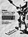
Congratulations!
Thank you for purchasing Yamaha’s MFC10 MIDI Foot Controller.
The MFC10 is a versatile MIDI foot control device that can transmit program changes and
control changes to control effectors, tone generators, keyboards, MIDI guitars, rhythm
machines, etc..
In addition to the onboard foot controller, up to 4 optional external foot controllers or
switches can also be connected to the MFC10 for increased control versatility.
In order to make full use of the MFC10’s features and functions, we recommend that you
read this manual thoroughly and keep it in a safe place for future reference.
Contents
Precautions................................................................................................................... 2
Power Supply ............................................................................................................... 3
Nomenclature ............................................................................................................... 4
Functions du MFC10.................................................................................................... 6
2 Modes .....................................................................................................6
Foot Controller Settings ...................................................................................7
All memory MIDI Channel Assign ........................................................................7
Bulk Dump ..................................................................................................7
Normal Mode ................................................................................................................ 8
Program Change Memory .................................................................................9
Program Change Memory Control (Transmit) ..........................................................9
Program Change Memory Edit .........................................................................10
Function Memory...........................................................................................12
Function Memory Control (Transmit) ..................................................................12
Edit Function Memory ...................................................................................13
About the TOGGLE ON-OFF/NUMBER OF PGM settings.................................18
MIX Mode ....................................................................................................................19
MIX Mode Memory Control (Transmit) ................................................................20
Editing MIX mode ........................................................................................21
The MIX mode’s Function Memory ............................................................21
Foot Controller ...........................................................................................................22
Editing FC (Foot Controller) data ......................................................................22
All Memory MIDI Channel Number Assign...............................................................24
Bulk Dump ..................................................................................................................25
Bulk Dump (Transmission) ..............................................................................25
Bulk Dump (Receive) .....................................................................................25
Initialize .......................................................................................................................26
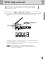
MFC10 Sample Setups...............................................................................................27
MIDI Guitar System........................................................................................27
MIDI Keyboard System ...................................................................................28
MIDI Effector System .....................................................................................28
MIDI Sequencer or Rhythm Programmer System .................................................29
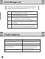
Error Messages ..........................................................................................................30
Trouble Shooting........................................................................................................30
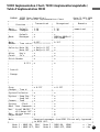
MIDI Implementation Chart ....................................................................................................... 31
MIDI data format ....................................................................................................................... 32
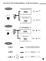
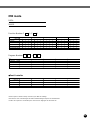
Operation Guide........................................................................................................................ 35
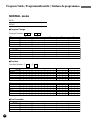
Program Table........................................................................................................................... 36
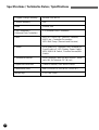
Specifications ............................................................................................................................ 40

2
Precautions
!! PLEASE READ THIS BEFORE PROCEEDING !!
■ Location
Do not expose the MFC10 to the following
conditions to avoid deformation, discoloration,
or more serious damage.
• Direct sunlight (e.g. near a window).
• High temperatures (e.g. near a heat source,
outside, or in a car during the daytime).
• Excessive humidity.
• Excessive dust.
• Strong vibration.
■ USE THE CORRECT POWER SUPPLY
• Power to the MFC10 should be supplied
only from the appropriate Yamaha AC
adaptor (the PA-3B or another adaptor
specifically recommended by Yamaha). Use
of another adaptor may cause serious
damage to the unit. Also make sure that the
adaptor you have is appropriate for the AC
mains supply voltage in the area where you
intend to use the MFC10. (The correct
input voltage is marked on the adaptor.)
■ Power Supply
• Turn the power switch OFF when the
instrument is not in use.
• The power adaptor should be unplugged
from the AC outlet if the MFC10 is not to
be used for an extended period of time.
• Unplug the MFC10 during electric storms.
• Avoid plugging the MFC10 into the same
AC outlet as appliances with high power
consumption, such as electric heaters or
ovens. Also avoid using multi-plug adaptors
since these can result in reduced sound
quality and possibly damage.
■ Turn Power OFF When Making Connections
• To avoid damage to the MFC10 and other
devices to which it is connected (a sound
system, for example), turn the power
switches of all related devices OFF prior to
connecting or disconnecting audio and MIDI
cables.
■ MIDI Connections
• When connecting the MFC10 to MIDI
equipment, be sure to use high-quality
cables made especially for MIDI data
transmission.
• Avoid MIDI cables longer than about 15
meters. Longer cables can pick up electrical
noise that can causes data errors.
■ Handling and Transport
• Never apply excessive force to the controls,
connectors or other parts of the instrument.
• Always unplug cables by gripping the plug
firmly, not by pulling on the cable.
• Disconnect all cables before moving the
instrument.
• Physical shocks caused by dropping,
bumping, or placing heavy objects on the
instrument can result in scratches and more
serious damage.
■ Cleaning
• Clean the cabinet and panel with a dry soft
cloth.
• A slightly damp cloth may be used to
remove stubborn grime and dirt.
• Never use cleaners such as alcohol or
thinner.
• Avoid placing vinyl objects on top of the
instrument (vinyl can stick to and discolor
the surface).
■ Electrical Interference
• This instrument contains digital circuitry
and may cause interference if placed too
close to radio or television receivers. If this
occurs, move the instrument further away
from the affected equipment.
■ Data Backup
• The MFC10 contains a special read-write
memory without a battery, that retains the
contents of its internal memory even when
the power is turned OFF.
■ Service and Modification
• The MFC10 contains no user serviceable
parts. Opening it or tampering with it in any
way can lead to irreparable damage and
possibly electric shock. Refer all servicing
to qualified YAMAHA personnel.
YAMAHA is not responsible for damage caused by improper handling or operation.

3
DC IN
POWER
ON/
OFF
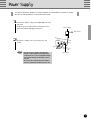
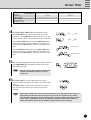
Power Supply
Use the PA-3B power adaptor (or another adaptor recommended by Yamaha) to supply
the MFC10 with power from a convenient wall socket.
2
Plug the AC adaptor into any convenient AC wall
socket.
1
Connect the adaptor’s plug into the [DC IN] jack on the
rear panel.
Wrap the power cord around the cord stopper hook to
prevent accidental unplugging during use.
Cord Stopper
Wall Socket
Power Adaptor
• Do not use an AC adaptor other than the
PA-3B, or other adoptors recommended by
Yamaha. The use of any incompatible adaptor
may result in damage, overheating, or fire to
the unit.
• Be sure to disconnected the power adaptor
from the outlet when the MFC10 is not in use.

4
Nomenclature
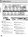
Front Panel
STATUS
DATA/CTRL
BANK MSB/MAX
BANK LSB/MIN
TOGGLE ON-OFF
/NUMBER OF PGM
DEC
/NO
INC
/YES
MEMORY
EDIT
FC
EDIT
WRITE
/EXIT
±10
8.8.8
.
1
2
4 3 5 6
7
8
0
9
POWER
ON/ OFF DC IN
FOOT
5432 OUTINWX IN
CONTROLLER/SWITCH MIDI
FOOT CONTROLLER 1
$
%^
&*
11
11
1 Parameter Lamp (see page 11, 16)
The currently selected parameter lamp will flash when
in the edit mode.
2 LED Display (see page 6)
Memory numbers, program changes and functions
(control changes) saved in memory, parameters, etc.,
are indicated in the display.
33
33
3 [INC/YES] (see page 11, 17)
Increases (INC) edit number values in the Play mode
and parameter data values in the Edit mode, and to
save data that has been edited, the YES button is used
to confirm the save operation.
44
44
4 [DEC/NO] (see page 11, 17)
Decreases (DEC) edit number values in the Play mode
and parameter data values in the Edit mode, and when
confirmation of the save operation of edited data is
requested, the NO button cancels the save operation.
55
55
5 [MEMORY EDIT] (see page 11, 16)
Enters the Memory Edit mode and selects edit param-
eters.
66
66
6 [FC EDIT] (see page 22)
Enters the Foot Controller Edit mode and selects edit
parameters.
77
77
7 [WRITE/EXIT] (see page 11, 17)
Exits the Edit mode and returns to the Normal control
mode. At this time it is necessary to press the [INC/
YES] button or [DEC/NO] button to either confirm or
cancel the data overwrite operation.
88
88
8 [FUNCTION] Foot switch (see page 6)
Switches between Program Change Memory and
Function Memory when in the Normal Mode.
In the Mix Mode, switches between Mix mode and
Function Memory.
■ Front Panel
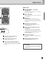
Rear Panel
* When the lamp above the [FUNCTION] foot switch
is lit, the MFC10 is in Function Memory.

5
!
MIDI WX NORMAL — MIX
FUNCTION
# @
99
99
9 [1]-[0] Foot switch (see page 9, 12)
Selects Memory Numbers.
00
00
0 [x10] Foot switch (see page 9, 12)
Select the 100's or 10's digit.
!!
!!
! Onboard Foot Controller (see page 22)
The Foot Controller can be used to transmit control
changes, after touch, pitch bend, etc., to external MIDI
devices.
Nomenclature
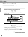
■ Rear Panel
@@
@@
@ [FUNCTION NORMAL — MIX] Switch
(see page 8, 19)
Selects the mode that the MFC10 is to be operated in,
Normal mode or Mix mode.
##
##
# [MIDI — WX] Switch
Selects whether MIDI data is received via the WX jack
or the MIDI IN jack.
$$
$$
$ [WX IN] Jack
A Yamaha Wind MIDI Controller WX7/11 can be
directly connected to this jack. (The MFC10 supplies
electric power to the WX7/11, so the BT-7 Power Box is
not needed.)
%%
%%
% [MIDI IN/OUT] Jacks (see page 27)
Using a MIDI cable, external MIDI devices can be
connect to the MFC10.
^^
^^
^ [FOOT CONTROLLER/SWITCH 2-5] Jacks
(see page 22)
These jacks allow the connection of up to 4 optional
foot controllers or foot switches to the MFC10. The
connected foot controllers or foot switches can be used
to control MIDI data in the same manner as the
onboard foot controller.
&&
&&
& [DC IN] Jack (see page 3)
Connect the power adaptor here to supply the MFC10
with power.
**
**
* [POWER ON/OFF] Switch (see page 8)
Turns the MFC10’s power on or off.
User Memo Sticker
The supplied User Memo Sticker can be applied
next to the number plate above each foot switch to
write memos on.

6
MFC10 Functions
When a foot switch is pressed, MIDI data (program changes/function data) stored in the
MFC10’s internal memory is transmitted to external MIDI devices.
• Program Change Data Program change data transmitted from the MFC10 can select
voices, etc., on other MIDI devices.
Bank select data can be transmitted along with program change
data as well.
• Function Data The MFC10 can transmit the following function data to control
other MIDI devices.
* Values in parentheses are shown in the display.
• NOTE ON/OFF (90-9F)
• CONTROL CHANGE (b0-bF)
• PROGRAM CHANGE (C0-CF)
• SONG SELECT (F3)
• START (FA)
• CONTINUE (Fb)
• STOP (FC)
• SECTION CONTROL (F0)
• TEMPO CONTROL (Ft)
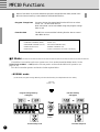
■ 2 Modes................................................................................................
Switch
STATUS
DATA/CTRL
BANK MSB/MAX
BANK LSB/MIN
TOGGLE ON-OFF
/NUMBER OF PGM
DEC
/NO
INC
/YES
MEMORY
EDIT
FC
EDIT
WRITE
/EXIT
±10
STATUS
DATA/CTRL
BANK MSB/MAX
BANK LSB/MIN
TOGGLE ON-OFF
/NUMBER OF PGM
DEC
/NO
INC
/YES
MEMORY
EDIT
FC
EDIT
WRITE
/EXIT
±10
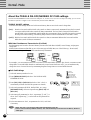
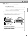
The MFC10’s foot switches can be set to operate in one of two modes (Normal Mode/Mix Mode). Use the
[FUNCTION NORMAL — MIX] switch on the rear panel to set the mode the MFC10 will operate in. (see
page 5, 8, 19)
How the foot switches operate in each mode is further explained below.
[In this mode, Program Change Memory and Function Memory are independent of each other.]
NORMAL — MIX
FUNCTION
• NORMAL mode
Function memory
(100 types)
Program change memory
(128 types)
Function lamp is lit
Function lamp is off

7
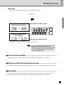
MFC10 Functions
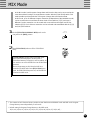
• MIX mode
STATUS
DATA/CTRL
BANK MSB/MAX
BANK LSB/MIN
TOGGLE ON-OFF
/NUMBER OF PGM
DEC
/NO
INC
/YES
MEMORY
EDIT
FC
EDIT
WRITE
/EXIT
±10
11
15
21
25
F06
F00
~
,
11 15
~
,
31 35
~
,
41 45
~
,
51 55
~
NORMAL — MIX
FUNCTION
Function memory (5 types)
Program change memory
(5 x 5 types)
[In this mode, Program Change Memory and Function Memory are mixed.]
Upper level foot switches [6]-[0]
Lower level foot switches [1]-[5]
• To access all 100 (F00-F99) Function Memory types, press
the [FUNCTION] switch, and it’s lamp will light.
• In the MIX mode, Program Change memory (25 memories)
is stored and played independent of Program Change
memory in the NORMAL mode.
■ Foot Controller Settings.....................................................................
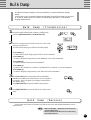
■ Bulk Dump ...........................................................................................
Internal data for the Normal mode Program Change Memory, the Mix mode Program Change Memory, and
Function Memory and Foot Controller Memory (1-5) can be transmitted via MIDI OUT. (see page 25)
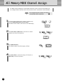
■ All Memory MIDI Channel Number Assign........................................
The settings for all MIDI channels, in all assigned memories, can be set to the same MIDI channel. (see page 24)
Sets parameters for the onboard Foot Controller and the external Foot Controllers 2-5. (see page 22)

8
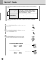
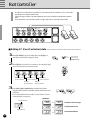
Normal Mode
Both Program Change Memory and Function Memory can be accessed in the Normal
Mode.
Press the [FUNCTION] to switch between Program Change Memory and Function
Memory.
There are 100 memory allocations for Function data
(control change etc.). By selecting a memory
number, its stored function data is transmitted to
external devices via the MIDI OUT terminal.
There are 128 memory allocations for Program
Change data. By selecting a memory number, its
stored program change is transmitted to external
devices via the MIDI OUT terminal.
Function Memory
Program Change Memory
1
Press the [POWER ON/OFF] switch on the rear panel to turn
the power on.
2
Set the [FUNCTION NORMAL—MIX] switch on the rear
panel to the [NORMAL] position.
• Program Change Memory (128 types)
• Function Memory (100 types)
Function lamp is lit.
Function lamp is off.
001 128
~
F00 F99
~
3
Press [FUNCTION] to switch between Program Change
Memory (see page 9) and Function Memory (see page 12).
POWER
ON/ OFF
NORMAL — MIX
FUNCTION

9
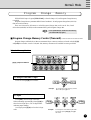
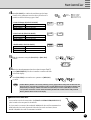
Normal Mode
If FUNCTION lamp is lit, press [FUNCTION], so that the lamp is off, and Program Change Memory
is enabled.
Program Change Memory transmits MIDI channel numbers 1-16 and program change data (001-128)
that are stored in memory.
There are 128 memory allocations in which Program Change data can be saved. Also, Bank
Select data (00=MSB, 20=LSB) can be transmitted along with Program Change data.
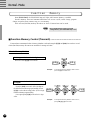
Program Change Memory
■ Program Change Memory Control (Transmit) ..................................
STATUS
DATA/CTRL
BANK MSB/MAX
BANK LSB/MIN
TOGGLE ON-OFF
/NUMBER OF PGM
DEC
/NO
INC
/YES
MEMORY
EDIT
FC
EDIT
WRITE
/EXIT
±10
8.8.8.
[1]-[0], [x10] foot switches
• Press [FUNCTION] to enable Function Memory
(the FUNCTION lamp lights).
084
081
Example: To change the current memory number
084 to 081 press [1] once.
To change or select the 1's digit.
To change and select both the 10's and
1's digits.
Press one of the [1]-[0] foot switches.
Press [x10]. (The 10's digit of the LED
flashes indicating input standby.) Press [1]-[0], to
select the 10's digit value. (The 1's digit flashes
indicating input standby.)
Once again press [1]-[0] to select the 1's digit
value.
Select a Memory Number
Example: To change the current Memory Number
023 to 082, press [x10], [8], and [2] in
that order.
023 082
Program changes and bank select data are transmitted when a memory number is selected with the [1]-[0]
and [x10] foot switches. A total of 128 (001-128) memory allocations are available for storing such data.

10
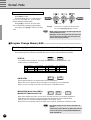
Normal Mode
To change and select all digits.
Press [x10] two times.
If the 100's digit value is 1, it will change to
0, if it is 0 it will change to 1. (The 10's digit
flashes indicating input standby.)
Press [1]-[0], to select the 10's digit value.
(The 1's digit flashes indicating input standby.)
Once again, press [1]-[0] to select the 1's digit
value.
• When [x10] is pressed twice, the 100's digit value will
alternate between 1 and 0.
• Attempting to select the number 000, will result in 001
being selected. Also, inputting any value above 128
will result in 128 being selected.
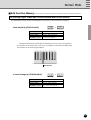
■ Program Change Memory Edit...........................................................
The following 4 types of MIDI data can be transmitted with Program Change Memory.
The transmitting Channel Number and MIDI data can be stored to individual Memory Numbers.
• STATUS
C0 CF
~
C0 Channel 1
C1 Channel 2
C2 Channel 3
C3 Channel 4
C4 Channel 5
C5 Channel 6
C6 Channel 7
C7 Channel 8
C8 Channel 9
C9 Channel 10
CA Channel 11
Cb Channel 12
CC Channel 13
Cd Channel 14
CE Channel 15
CF Channel 16
Cn (n=MIDI channel numbers 1-16) assigns the MIDI channel for voice selection. The
number is shown in hexadecimal.
Example: To change the current Memory Number 048 to
126, press [x10], [X10], [2], [6] in that order.
Two times
048 126
• BANK MSB (Bank Select MSB)
• BANK LSB (Bank Select LSB)
000oFF 127
~,
Bank select numbers are used to access voices other than the 128 voices normally available in
MIDI devices and GM devices. Program change data and bank select data (BANK MSB/
LSB:off, 000-127) must be transmitted together to access these voices.
Refer to the owner's manual of the receiving device for specific information on bank select data.
• DATA/CTRL
001 128
~
Sets program numbers (voice numbers 001-128) for transmission.
Refer to the owner's manual of the receiving device for details on voice assignments.
Refer to a GM voice map for the 128 voice allocations of GM MIDI devices.
• The default settings for each memory (001-128) is as
follows.
STATUS=C0 (Channel Number 1), DATA/CTRL=001-128
(same as the memory number), BANK MSB/MAX=off,
BANK LSB/MIN=off.

11
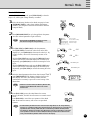
Normal Mode
How to Edit Memory
If the FUNCTION lamp is lit, press [FUNCTION], so that the
lamp is off, and Program Change Memory is enabled.
1
Select the Memory Number to be edited (see page 9). Press
[MEMORY EDIT] to edit to begin editing that Memory
Number. (The lamp above that foot switch and the STATUS
lamp will flash.)
2
Press [MEMORY EDIT] to cycle through the 4 edit param-
eters (the selected parameter’s light will flash).
3
Use [INC/YES] and [DEC/NO] to edit the parameter.
Press [INC/YES] to increase the value shown in the LED
display by 1, press [DEC/NO] to decrease the value by 1. By
holding a button, values will continuously increase or de-
crease.
Hold the [INC/YES] button and press the [DEC/NO] button
and the value shown in the LED display will increase by 10.
Repeatedly press [DEC/NO] to continue increasing the value
by 10.
Hold the [DEC/NO] button and press the [INC/YES] button
and the value shown in the LED display will decrease by 10.
Repeatedly press [INC/YES] to continue decreasing the value
by 10.
• TOGGLE ON-OFF/NUMBER OF PGM can not be
selected from Program Change Memory.
MEMORY
EDIT
Increase by 10
MEMORY
EDIT
DEC
/NO
INC
/YES
±10
DEC
/NO
INC
/YES
±10
001 128
128 001
DEC
/NO
INC
/YES
±10
DEC
/NO
INC
/YES
±10
Decrease by 10
WRITE
/EXIT
007
STATUS
DATA/CTRL
BANK MSB/MAX
BANK LSB/MIN
TOGGLE ON-OFF
/NUMBER OF PGM
STATUS settings
DATA/CONTROL settings
BANK MSB settings
BANK LSB settings
5
Press [INC/YES], to save the edited data to the current
Memory Number, The MFC10 will return to its normal control
mode.
Press [DEC/NO] to cancel the save operation of the edited
data. At this time the memory will revert to its pre-edited
contents.
DEC
/NO
INC
/YES
±10
DEC
/NO
INC
/YES
±10
• Another Memory Number from the same bank (10’s digit bank) can be easily edited by
pressing [1] - [0] without exiting from the edit mode. You must execute or cancel the save
operation for the currently edited data (the current Memory Number will flash) before
proceeding to edit the new number. Use [INC/YES] to execute or [DEC/NO] to cancel the
save operation. If data has not been edited, the Memory Number will not flash and the
newly selected Memory Number will be shown in the display.
4
After the desired parameters have been edited in steps 2 and 3,
press [WRITE/EXIT]. The Memory Number shown in the
LED display will flash. (The flashing number indicates
confirmation is necessary to proceed or cancel saving of the
edited data.)
• If data has not been edited, the Memory Number will
not flash and the MFC10 will return to its normal
control mode.

12
Normal Mode
Function Memory
Press [FUNCTION], the FUNCTION lamp will light, and Function Memory is enabled.
Function Memory stores and transmits MIDI data such as note on/off, control change, program
change, song select, start, continue, stop, etc., in its memory.
There are 100 (F00-F99) memory allocations in which Function Data can be saved.
• Press [FUNCTION] to enable to Program
Change Memory. (The FUNCTION lamp is off.)
■ Function Memory Control (Transmit) ................................................
Function data is transmitted when a Memory Number is selected using the [1]-[0] and [x10] foot switches. A total
of 100 (F00-F99) memory allocations are available for storing such data.
Example: To change the Memory Number “F84” to “F81”
press the [1] foot switch once.
Example: To change the Memory Number “F23” to “F47”,
press [x10], [4], [7] in that order.
F84
F81
Press one of the [1]-[0] foot switches.
Press the [x10] foot switch. (The 10's digit of
the LED flashes indicating input standby.) Press
[1]-[0], to select the 10's digit value. (The 1's digit
flashes indicating input standby.)
Once again press [1]-[0] to select the 1's digit
value.
To change and select the 1's digit.
To change and select both the 10's and
1's digits.
F23 F47
Select a Memory Number

13
Normal Mode
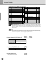
■ Edit Function Memory ........................................................................
The following 9 types of MIDI data can be transmitted with Function Memory.
The transmitting Channel Number and MIDI data can be stored to individual Memory Numbers.
DATA/CTRL 000-127 (Note Number)
BANK MSB/MAX 001-127 (Note On Velocity)
BANK LSB/MIN 001-127 (Note Off Velocity)
TOGGLE ON-OFF
Pn1-Pn4 (see page 18)
/NUMBER OF PGM
53
54 56 58 66 68 7061 63
55 57 59 60
C3
62 64 65 67 69 71
................
Transmits keyboard Note On/Off data. If a different note is set to each foot switch, the
foot switches can be used to play a scale. Also, if a sampler is connected to the MFC10 the
foot switches can be used to trigger samples.
•Control Change (b) [STATUS=b0-bF]
DATA/CTRL 000-127 (Control Number)
BANK MSB/MAX 000-127 (Switch On Data)
BANK LSB/MIN 000-127 (Switch Off Data)
TOGGLE ON-OFF
off, on, Pn1-Pn4 (see page 18)
/NUMBER OF PGM
Note Number
•Note On/Off (9) [STATUS=90-9F]
90 9F
~
b0 bF
~

14
Normal Mode
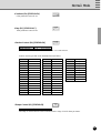
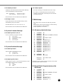
Control Change List (for GM, XG supported devices)
Control
Function GM XG
Number
0 Bank Select N Y
1 Modulation Y Y
5 Portamento Time N Y
6 Data Entry Y Y
7 Main Volume Y Y
10 Pan Pot Y Y
11 Expression Y Y
32 Bank Select N Y
38 Data Entry Y Y
64 Hold 1 (Damper Pedal) Y Y
65 Portamento N Y
66 Sostenuto (Chord Hold) N Y
67 Soft Pedal N Y
71 Harmonic Content N Y
72 Release Time N Y
73 Attack Time N Y
74 Brightness N Y
84 Portamento Control N Y
91 Extensive Use Effect 1 (Reverb) N Y
93 Extensive Use Effect 3 (Chorus) N Y
94 Extensive Use Effect 4 (Celeste) N Y
96 Data-Increment N Y
97 Data-Decrement N Y
98 NRPN(LSB) N Y
99 NRPN(MSB) N Y
100 RPN(LSB) Y Y
101 RPN(MSB) Y Y
120 All Sound Off N Y
121 Reset All Controllers Y Y
122 Local Control N Y
123 All Note Off Y Y
124 Omni Off N Y
125 Omni On N Y
126 Mono On N Y
127 Poly On N Y
GM (GM System Level 1)
[GM] (General MIDI is in addition to the MIDI standard which ensures that any GM-compatible
music data can be accurately played on any GM-compatible tone generator, regardless of the
maker. The GM mark is affixed to all software and hardware products that support the General
MIDI standard.
XG
[XG] is a MIDI format created by Yamaha which significantly imporves and expands upon the
General MIDI standard by providing a greater variety of high-quality Voices plus considerably
enhanced effect operations—while being fully compatible with GM.
GENERAL
•Program Change (C) [STATUS=C0-CF]
C0 CF
~
DATA/CTRL 001-128 (Program Number)
BANK MSB/MAX off, 000~127
BANK LSB/MIN off, 000~127
TOGGLE ON-OFF
Pn1-Pn4
(see page 18)
/NUMBER OF PGM
•Song Select (F3) [STATUS=F3]
F3
DATA/CTRL 000-127 (Song Number)
•Start (FA) [STATUS=FA]
Other parameters cannot be set.
FA
Y...Yes N...No

15
Normal Mode
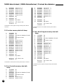
• Section Control (F0) [STATUS=F0]
* When c41 or c42 is selected, the device number must be set in BANK MSB/MAX.
F0
•Continue (Fb) [STATUS=Fb]
Other parameters cannot be set.
Fb
•Stop (FC) [STATUS=FC]
Other parameters cannot be set.
FC
DATA/CTRL c01-c42 (Section Number)
BANK MSB/MAX 01-16, - - -
(Device Number)
c17 Fill In AA1
c18 Fill In AA2
c19 Fill In AA3
c20 Fill In AA4
c21 Fill In AA5
c22 Fill In AA6
c23 Fill In AA7
c24 Fill In AA8
c25 Fill In AB1
c26 Fill In AB2
c27 Fill In AB3
c28 Fill In AB4
c29 Fill In AB5
c30 Fill In AB6
c31 Fill In AB7
c32 Fill In AB8
c33 Ending 1
c34 Ending 2
c35 Ending 3
c36 Ending 4
c37 Ending 5
c38 Ending 6
c39 Ending 7
c40 Ending 8
c41 Reset Start
c42 Stop & Rewind
c01 Intro 1
c02 Intro 2
c03 Intro 3
c04 Intro 4
c05 Intro 5
c06 Intro 6
c07 Intro 7
c08 Intro 8
c09 Main 1
c10 Main 2
c11 Main 3
c12 Main 4
c13 Main 5
c14 Main 6
c15 Main 7
c16 Main 8
Data for section types that can be transmitted are listed below.
• Tempo Control (Ft) [STATUS=Ft]
Ft
DATA/CTRL 030~250 (Tempo Value)
The tempo of external devices can be controlled within a range of 30-250 beats per minute.

16
Normal Mode
How to Edit Memory
1
Select the Function Memory to be edited, press [MEMORY
EDIT], to begin editing that memory number. (The lamp above
the foot switch and the STATUS lamp will flash.)
2
Press [INC/YES] and [DEC/NO] to select the Status (transmit
MIDI data and MIDI channel number) (the STATUS lamp will
flash).
The 1's digit (MIDI channel number 1-16) of Status is shown in
hexadecimal. (see page 10)
3
Press [MEMORY EDIT] to select the parameters set in the
procedures above for editing (the lamp will flash).
Song Select Start Continue Stop
STATUS F3 FA Fb FC
DATA/CTRL 0-127 –– –
BANK MSB/MAX ––––
BANK LSB/MIN ––––
TOGGLE ON-OFF
––––
/NUMBER OF PGM
Note On/Note Off Control Change Program Change
STATUS
90-9F b0-bF C0-CF
(0-F indicates MIDI channel numbers)
DATA/CTRL Note Number Control Number Program Number
BANK MSB/MAX Note On Velocity Switch On Data Bank MSB
BANK LSB/MIN Note Off Velocity Switch Off Data Bank LSB
TOGGLE ON-OFF
Pn1-Pn4
Toggle On/Off
Pn1-Pn4
/NUMBER OF PGM Pn1-Pn4
90...9F Transmit Note On/Off
b0...bF Transmit Control Change
CO...CF Transmit Program Change
F3 Transmit Song Select
FA Transmit Start
Fb Transmit Continue
FC Transmit Stop
FO Transmit Section Control
Ft Transmit Tempo Control
MEMORY
EDIT
MEMORY
EDIT
MIDI data
Channel number
90
STATUS
DATA/CTRL
BANK MSB/MAX
BANK LSB/MIN
TOGGLE ON-OFF
/NUMBER OF PGM
STATUS
DATA/CTRL
BANK MSB/MAX
BANK LSB/MIN
TOGGLE ON-OFF
/NUMBER OF PGM
DEC
/NO
INC
/YES
±10
DEC
/NO
INC
/YES
±10

17
Normal Mode
Increase by 10
Section Control Tempo Control
STATUS F0 Ft
DATA/CTRL c01 - c42 030- 250
BANK MSB/MAX Channel Number (if c41, c42 is used) –
BANK LSB/MIN ––
TOGGLE ON-OFF
––
/NUMBER OF PGM
4
Press [INC/YES] or [DEC/NO] to edit parameter values.
Press [INC/YES] to increase the value shown in the LED
display by 1, press [DEC/NO] to decrease the value by 1. By
holding a button, values will continuously increase or decrease.
Hold the [INC/YES] button and press the [DEC/NO] button
and the value shown in the LED display will increase by 10.
Repeatedly press [DEC/NO] to continue increasing the value
by 10.
Hold the [DEC/NO] button and press the [INC/YES] button
and the value shown in the LED display will decrease by 10.
Repeatedly press [INC/YES] to continue decreasing the value
by 10.
DEC
/NO
INC
/YES
±10
DEC
/NO
INC
/YES
±10
DEC
/NO
INC
/YES
±10
001 128
128 001
*(—) is displayed to indicate parameters that cannot be selected.
WRITE
/EXIT
F07
5
After the desired parameters have been edited in steps 3 and 4,
press [WRITE/EXIT]. The Memory Number shown in the
LED display will flash.
• If data has not been edited, the Memory Number will
not flash and the MFC10 will return to its normal
control mode.
6
Press [INC/YES], to save the edited data to the current
Memory Number, The MFC10 will return to its normal control
mode.
Press [DEC/NO] to cancel the save operation of the edited
data. At this time the memory will revert to its pre-edited
condition.
Decrease by 10
DEC
/NO
INC
/YES
±10
• Another Memory Number from the same bank (10’s digit bank) can be easily edited by pressing [1] - [0]
without exiting from the edit mode. You must execute or cancel the save operation for the currently
edited data (the current Memory Number will flash) before proceeding to edit the new number. Use [INC/
YES] to execute or [DEC/NO] to cancel the save operation. If data has not been edited, the Memory
Number will not flash and the newly selected Memory Number will be shown in the display.
DEC
/NO
INC
/YES
±10
DEC
/NO
INC
/YES
±10

18
About the TOGGLE ON-OFF/NUMBER OF PGM settings.
Normal Mode
TOGGLE ON-OFF/NUMBER OF PGM contains the settings for “on, off, Pn1, Pn2, Pn3, Pn4”. According to the setting, you can use the
foot switch to operate as a toggle on-off, or simultaneously transmit several MIDI data.
TOGGLE ON-OFF settings
TOGGLE ON-OFF settings can be used in Function Memory that are saved with control change data.
• [on]...... Press the foot switch and the MAX value (switch on data) is continuously transmitted. Press the foot switch
once again and the MIN value (switch off data) is transmitted. The foot switch’s lamp will flash from the
time the MAX value is transmitted, until the MIN value is transmitted. Even if another foot switch is pressed,
the lamp will remain flashing. (The flashing lamp indicates continuous transmission of the MAX value.)
• [oFF]....Hold the foot switch and the MAX value (switch on data) is transmitted. Release the foot switch and the
MIN value (switch off data) is transmitted.
MIDI Data Simultaneous Transmission (Pn1-Pn4)
Pn1-Pn4 settings can be used in Function Memory that are saved with Note ON/OFF, control change, and program
change data.
Within Function Memories F00-F49, up to 4 of the same type of MIDI data (one of the following— Note On/Off,
Control Change, Program Change) can be simultaneously transmitted.
Pn4
Pn3
Pn2
Pn1
Pn4
Pn3
Pn2
Pn1
Pn4
Pn3
Pn2
Pn1
F00 F01 F49
For example, you can transmit several note on/off data over the same MIDI channel to play chords, or transmit control
change data over several MIDI channels to simultaneously control external effectors. Also, you can simultaneously
change the voices of several devices by transmitting Program Change Data over several MIDI channels.
■ Pn1-Pn4 Settings
1
Select the memory number to be set.
2 Press [MEMORY EDIT] and select “TOGGLE ON-OFF/
NUMBER OF PGM”.
3 Press [INC/YES] or [DEC/NO] and select “Pn1” (“Pn1” is
automatically selected when the edit operation is entered).
4 Select each parameter (STATUS, DATA/CTRL, etc.) using
[MEMORY EDIT], and set as required using [INC/YES] and
[DEC/NO].
5 After setting all parameters for “Pn1”, repeat steps 2 and 3 to
select “Pn2”. Repeat step 4 to select and set each parameter as
required.
6 In the same manner as “Pn2”, set parameters for “Pn3”, and “Pn4”
if necessary.
MEMORY
EDIT
Pn1
DEC
/NO
INC
/YES
±10
DEC
/NO
INC
/YES
±10
Pn2
MEMORY
EDIT
STATUS
DATA/CTRL
BANK MSB/MAX
BANK LSB/MIN
TOGGLE ON-OFF
/NUMBER OF PGM
• When “Pn1-Pn4” is set, the toggle setting will automatically be set to ON.
• If data is stored in Memory Numbers F00-F49, “Pn1” will automatically be selected when the Memory Number is
edited again.

19
MIX Mode
In the MIX mode, both Program Change data and Function data can be accessed at the
same time without having to change between modes with the [FUNCTION] switch. This
mode provides quick transmission of Program Change data and Function data.
In this mode, up to 25 different Program memories (independent of the NORMAL mode)
can be saved and accessed from the lower level of foot switches [1]-[5], and up to 5
different Function memories can be saved and accessed from the upper level of foot
switches [6]-[0]. Each of those memories can be selected and transmitted with the [1]-[0]
and [x10] foot switches.
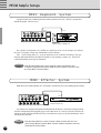
1
Set the [FUNCTION NORMAL-MIX] switch on the
rear panel to the [MIX] position.
NORMAL — MIX
FUNCTION
2
Press [FUNCTION] and turn off the FUNCTION
lamp.
If [FUNCTION] is pressed while in the MIX mode
(the FUNCTION lamp lights), the MIX mode’s
FUNCTION memory (see page 21) will be enabled. All
foot switches can access the MFC10’s 100 FUNCTION
memories.
The 10's digit setting is valid when the MFC10 is
returned to the MIX mode. Press [FUNCTION] once
again, the FUNCTION lamp turns off, and the MFC10
is returned to MIX mode.
* The contents of each Function Memory number is same data between NORMAL mode and MIX mode. Program
Change Memory exists independently in each mode.
* Default setting for Program Change Memory in the MIX mode.
11[C0, 00], 12[C0, 01], 13[C0, 02], 14[C0, 03], 15[C0, 04], 21[C0, 05], 22[C0, 06], ...
Seite wird geladen ...
Seite wird geladen ...
Seite wird geladen ...
Seite wird geladen ...
Seite wird geladen ...
Seite wird geladen ...
Seite wird geladen ...
Seite wird geladen ...
Seite wird geladen ...
Seite wird geladen ...
Seite wird geladen ...
Seite wird geladen ...
Seite wird geladen ...
Seite wird geladen ...
Seite wird geladen ...
Seite wird geladen ...
Seite wird geladen ...
Seite wird geladen ...
Seite wird geladen ...
Seite wird geladen ...
Seite wird geladen ...
-
 1
1
-
 2
2
-
 3
3
-
 4
4
-
 5
5
-
 6
6
-
 7
7
-
 8
8
-
 9
9
-
 10
10
-
 11
11
-
 12
12
-
 13
13
-
 14
14
-
 15
15
-
 16
16
-
 17
17
-
 18
18
-
 19
19
-
 20
20
-
 21
21
-
 22
22
-
 23
23
-
 24
24
-
 25
25
-
 26
26
-
 27
27
-
 28
28
-
 29
29
-
 30
30
-
 31
31
-
 32
32
-
 33
33
-
 34
34
-
 35
35
-
 36
36
-
 37
37
-
 38
38
-
 39
39
-
 40
40
-
 41
41


Yamaha MFC10 Bedienungsanleitung
- Kategorie
- Digitale Klaviere
- Typ
- Bedienungsanleitung
in anderen Sprachen
- English: Yamaha MFC10 Owner's manual
- français: Yamaha MFC10 Le manuel du propriétaire
- español: Yamaha MFC10 El manual del propietario
- italiano: Yamaha MFC10 Manuale del proprietario
- русский: Yamaha MFC10 Инструкция по применению
- Nederlands: Yamaha MFC10 de handleiding
- português: Yamaha MFC10 Manual do proprietário
- dansk: Yamaha MFC10 Brugervejledning
- polski: Yamaha MFC10 Instrukcja obsługi
- čeština: Yamaha MFC10 Návod k obsluze
- svenska: Yamaha MFC10 Bruksanvisning
- Türkçe: Yamaha MFC10 El kitabı
- suomi: Yamaha MFC10 Omistajan opas
- română: Yamaha MFC10 Manualul proprietarului
Verwandte Artikel
-
Yamaha DG100 Benutzerhandbuch
-
-
-
Yamaha NULL Bedienungsanleitung
-
-
-
-
-
-