protech Skystar Benutzerhandbuch
- Kategorie
- Ferngesteuertes Spielzeug
- Typ
- Benutzerhandbuch

Skystar - 1
INSTRUCTION MANUEL • GEBRUIKSAANWIJZING • PLAN DE MONTAGE • ANLEITUNG
T0352
WARNING ! This R/C kit and the model
you will build is not a toy.
LET OP ! Deze bouwdoos van een
radiobestuurd vliegtuig is geen
speelgoed.
ATTENTION ! Ce kit d’avion R/C n’est
pas un jouet.
ACHTUNG ! Dieser Bausatz von
ferngesteurte model
ist kein Spielzeug.
version: 06/08/2002 • T0352
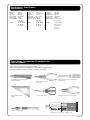
2500 g.
48,0 dm
2
1260 mm
1650 mm

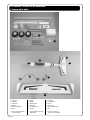
2 - Skystar
1. Fuselage
2. Tailplane
3. Rudder fin
4. Noseleg
5. Main landinggear
6. Wing
+ all necessary hardware
is also included
1. Romp
2. Stabilo
3. Richtingsroer
4. Neuswiel
5. Landingsgestel
6. Vleugel
+ alle toebehoren zijn ook
bijgeleverd
1
2
5
6
3
4
Kit content / Inhoud van de bouwdoos /
Contenu de la boîte
1. Fuselage
2. Stabilisateur
3. Dérive
4. Train avant
5. Train d’attérissage
6. Aile
+ Ainsi que toutes les
pièces d’accastillages.

Skystar - 3
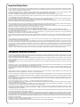
Important Safety Notes.
Be sure to read right through the instructions covering assembly and operation of your model before you attempt to operate it for the first time. You alone are responsible
for the safe operation of your radio-controlled model. Young people should only be permitted to build and fly these models under the instruction and supervision of an
adult who is aware of the hazards involved in this activity.
Use only matching polarised connectors. All cables, connectors and the battery if home-assembled must be insulated to prevent short circuits. Never attempt to combine
different types of plug and socket - e.g. tin-plated and gold-plated types - as such combinations are bound to be unreliable.
NC batteries are capable of holding and releasing enormous amounts of energy, and as such represent a constant hazard of explosion and fire.
We have no control over the way you build and operate your RC model aircraft, and for this reason we are obliged to deny all liability for accidents. All we can do is point
out the hazards and make sure you are aware of them.
If you need help, please enlist the aid of an experienced modeller, a model club or enrol at a model flying training school, Model shops and the specialist model press
are also good sources of information. The best course is always to join a club and fly at the approved model flying site.
Rubber bands deteriorate with age and become brittle. Replace them from time to time to maintain the safety and reliability of your model. Stretch all rubber bands
before use to check that they are still strong enough for their purpose.
Motors should only be run in the open air! The powerful suction of the propeller and the volume of air which it accelerates can easily lead to accidents in enclosed spaces
(e.g. pictures falling down, curtains sucked into the propeller). The model must be held securely by an assistant at all times.
Keep well clear of the rotational plane of propellers - don't stand in line with it or in front of it. You never know when some part may come loose and fly off at high speed,
hitting you or anybody else in the vicinity. Never touch the revolving propeller with any object.
There must be no chance of any object getting in the way of the propeller and preventing it rotating.
Take care with loose clothing such as scarves, loose shirts etc. Flapping cloth can easily be sucked into the area of the propeller and then get tangled in it.
If you start your motor when the model is standing on loose or sandy ground, the propeller will suck up sand and dust and hurl it around. and it could easily get in your
eyes. Wear protective goggles at such times.
Every time you intend to operate your model check carefully that it and everything attached to it (e.g. propeller, gearbox,RC components etc.) are in good condition and
undamaged. If you find a fault do not fly the model until you have corrected it.
Satisfy yourself that your frequency is vacant before you switch on. Radio interference caused by unknown sources can occur at any time without warning. If this should
happen, your model will be uncontrollable and completely unpredictable. Never leave your radio control system unguarded, as other people might pick it up and try to
use it.
Check that nothing is in the way of the propeller before you switch on the electric motor. Never attempt to stop the spinning propeller.Electric motors with a propeller
attached should only be run when installed securely.
lf you are to fly your model safely and avoid problems it is essential that you are aware of its position and attitude throughout each flight - so don't let it fly too far away!
lf you detect a control problem or interference during a flight,immediately land the model to prevent a potential accident Note that the transmitter throttle stick must be
set to the OFF (motor stopped) position before you switch on the power system. To avoid the electric motor starting unexpectedly, switch on the transmitter first. then the
receiving system. Use the reverse sequence when switching off: receiver first, then the transmitter. Check that the control surfaces move in the correct "sense" when you
operate the sticks.
Please don't misunderstand the purpose of these notes. We only want to make you aware of the many dangers and hazards which can arise if you lack knowledge and
experience, or work carelessly or irresponsibly. If you take reasonable care model flying is a highly creative, instructive, enjoyable and relaxing pastime.
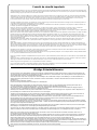
Belangrijke Veiligheidsinstructies
Lees de instructies betreffende montage en werking van je model vooraleer u het de eerste maal in gebruik neemt. U alleen bent verantwoordelijk voor de veilige
werking van uw radiobestuurd model. Kinderen zijn enkel toegestaan om deze modellen te bouwen en te vliegen onder het toeziend oog van een volwassene, die zich
bewust is van de gevaren die dit met zich meebrengt.
Gebruik enkel passende gepolariseerde verbindingsstukken. Alle kabels, verbindingsstukken en de batterij, indien deze zelf samengesteld is, moeten geïsoleerd
worden om kortsluiting te voorkomen. Poog nooit verschillende types van pluggen en contacten te kombineren (vb.tin-en goudcontacten), daar zulke combinaties
onbetrouwbaar zijn.
NC-batterijen zijn geschikt om enorme hoeveelheden energie vast te houden en vrij te geven. Zodoende vertegenwoordigt een batterij een constant risico op explosie
en brandgevaar.
Wij hebben geen controle over de manier waarop u het RC-vliegtuig bouwt en gebruikt. Daarom zijn wij verplicht om alle aansprakelijkheid voor ongevallen van de hand
te wijzen. Het enige dat in onze mogelijkheden ligt is u te waarschuwen voor de risico’s.
Als u hulp nodig heeft, roep dan de bijstand van een ervaren modelbouwer of een modelbouwclub in, of schrijf u in bij een modelvliegclub. Modelshops en de
gespecialiseerde pers zijn eveneens een geschikte bron van informatie. De beste les is echter zich aan te sluiten bij een club en te vliegen op de goedgekeurde
vliegplaatsen.
Rubber elastieken verslijten met het gebruiken en worden broos. Vervang ze tijdig, zodoende stelt u de veiligheid en de betrouwbaarheid van uw model veilig. Span alle
rubber elastieken op vooraleer u ze gebruikt om te controleren of ze nog sterk genoeg zijn.
Motoren mogen enkel buiten in openlucht lopen! De sterke zuigkracht van de propeller en de luchtverplaatsing die deze veroorzaakt, kan in kleine ruimten makkelijk een
ongeval tot gevolg hebben (vb. schilderijen die naar beneden vallen, een gordijn dat in de propeller gezogen wordt). Het model moet steeds stevig worden vastgehouden
door een helper.
Houdt de rotatiebaan van een propeller vrij, sta er nooit voor of in de lijn van de propeller. Er kan steeds een deel loskomen en met hoge snelheid wegvliegen, zodat het
uzelf of iemand anders in de omgeving kan verwonden. Raak de ronddraaiende propeller nooit met enig voorwerp aan. Vermijdt steeds dat welk voorwerp ook het
draaien van de propeller verhindert.
Pas op met losse kleding zoals sjaals, losse shirts, … Losse kleding kan makkelijk in de propeller gezogen worden.
Als u de motor start terwijl deze op losse of zanderige grond staat, zal de propeller het zand opzuigen en rondslingeren zodat het in je ogen kan komen. Draag dus
steeds een veiligheidsbril op zo’n momenten.
Controleer, elke keer als u een model wil gebruiken, zorgvuldig of het model en alles wat erbij hoort (vb. propeller, aandrijving, RC-onderdelen, …) in goede staat en
onbeschadigd is. Als u een fout bemerkt, vlieg dan niet met het model tot u de fout hebt opgelost.
Verzeker uzelf ervan dat de frequentie vrij is vooraleer u de zender aanzet. Radiostoringen veroorzaakt door vreemde bronnen kunnen op elk moment en zonder
waarschuwing voorkomen. Als dit gebeurt is je model oncontroleerbaar en volledig onvoorspelbaar. Laat uw radiobesturing nooit onbewaakt achter, andere mensen
zouden kunnen proberen het te gebruiken.
Controleer of er niets in de baan van de propeller is vooraleer u de electromotor aanzet. Probeer nooit de draaiende propeller te stoppen. Electromotoren verbonden met
een propeller mogen enkel lopen als deze veilig geïnstalleerd is.
Als u uw model veilig wil vliegen en u wil problemen vermijden, dan is het essentieel dat u zich bewust bent van zijn positite en hoogte tijdens iedere vlucht. Laat het dus
niet te ver weg vliegen ! Als u een controleprobleem of storingen ontdekt gedurende een vlucht, landt dan onmiddellijk om een mogelijk ongeval te voorkomen. Bemerk
dat de zenderstick voor de motorfunctie in de off-stand moet staan vooraleer u het systeem aanzet. Om te voorkomen dat de electromotor onverwacht start, zet eerst
de zender aan, later pas de ontvanger. Gebruik de omgekeerde volgorde bij het afzetten : eerst de ontvanger, dan de zender. Controleer of de roeren in de juiste richting
bewegen als u de sticks gebruikt.
Heb begrip voor het doel van deze opmerkingen. Wij willen u enkel opmerkzaam maken voor de vele gevaren en risico’s die zich kunnen voordoen als u kennis en
ervaring mist, nonchalant of onverantwoordelijk te werk gaat.
Als u redelijk zorg draagt, is modelvliegen een zeer creatieve, leerrijke, plezierige en ontspannende vrijetijdsbesteding.

4 - Skystar
Conseils de sécurité importants
Avant de tenter la première mise en service, la totalité des instructions de montage et d’utilisation devront être attentivement lues. Vous êtes seul responsable de la
sécurité d’utilisation de votre modèle volant R/C. Il est conseillé aux adolescents de se faire assister pour la construction et pour les premiers vols par un adulte déjà
familiarisé au danger que peut représenter un modéle radiocommandé.
Utilisez toujours des connecteurs adaptés, avec sécurité contre les inversions de polarité. Tous les conducteurs de courant, les connecteurs ainsi que les batteries
de propulsion de confection personnelle devront être parfaitement isolés contre les courts-circuits. N’utilisez jamais des combinaisons de connecteurs, par ex. des
contacts en métal ordinaire avec des contacts dorés, car dans ce cas aucune sécurité de fonctionnement ne peut être garantie. Evitez les court-circuits et les
inversions de polarité car la forte énergie contenue dans les batteries NC pourrait entraîner un danger d’explosion et d’incendie.
Un modèle volant R/C ne peut évoluer correctement que s’il a été construit et réglé conformément aux instructions de montage et seule une utilisation prudente et
responsable évitera de provoquer des dommages corporels ou matériels.
Le fabricant n’a cependant aucune possibilité d’influencer la construction et l’utilisation d’un modèle de sa production. C’est pourquoi nous attirons l’attention sur
les dangers représentés en dégageant toute responsabilité.
Faites-vous assister par un modéliste expérimenté, ou inscrivez - vous dans une association ou une école de pilotage. Vous pourrez en outre consulter votre
revendeur et la presse spécialisée sur le sujet. Le mieux est de faire partie d’un club d’aéromodélisme pour pouvoir voler sur un terrain autorisé.
Les bandes élastiques vieillissent, elles deviennent cassantes et inutilisables dans le temps. C’est la raison pour laquelle il conviendra de les remplacer régulièrement
par des neuves. Avant chaque utilisation, vérifier la solidité du caoutchouc par des essais de tension.
Effectuez les essais de fonctionnement uniquement à l’extérieur. La forte aspiration de l’hélice et la masse d’air rapidement accélérée derrière son champ de rotation
peuvent provoquer un accident dans une pièce fermée (la chute d’un tableau, l’aspiration des rideaux, etc.). Le modèle devra être fermement tenu par un aide.
Ne vous tenez jamais dans le champ de rotation de l’hélice! Une partie peut se détacher et être éjectée à très haute vitesse avec une forte inertie et vous toucher, ou
une tierce personne. Veillez également à ce qu’aucun objet quelconque ne vienne en contact avec l’hélice en rotation! Le blocage de l’hélice par un objet quelcon-
que doit être absolument exclu.
Veillez également aux vêtements flottants, tels qu’écharpe ou cravate qui peuvent être aspirés et s’enrouler sur l’hélice.Lorsqu’un modèle se trouve sur un sol
sablonneux avec l’hélice en rotation, celle-ci peut aspirer du sable ou des gravillons et vous les projeter dans les yeux. Portez des lunettes de protection si
nécessaire.
Avant chaque utilisation, contrôlez le modèle et toutes les pièces qui y sont rattachées (par ex. hélice, réducteur, élément R/C etc..) afin de vérifier leur fixation ou
détecter une possible détérioration. Ce n’est qu’après avoir remédié à tous les défauts éventuels que le modèle sera en ordre de vol. Assurez-vous que la fréquence
que vous utilisez est libre avant de mettre votre émetteur en contact! Une perturbation peut toujours se produire pour une cause inconnue, sans prévenir! Le modèle
devient alors incontrôlable et livré à lui-même! Ne laissez pas votre émetteur sans surveillance pour éviter une manipulation par un tiers.
Ne mettez le moteur électrique en contact que si aucun objet ou autre ne se trouve dans le champ de rotation de l’hélice. Ne tentez pas d’arrêter l’hélice à la main.
Ne faites tourner le moteur avec l’hélice que lorsqu’il est monté dans le modèle.
La position du modèle doit toujours être nettement identifiable durant tout le vol pour garantir un pilotage sûr. Si l’on remarque l’influence d’une perturbation durant
le vol, se préparer immédiatement à atterrir par mesure de sécurité.
Faites une vérification complète de l’installation R/C et de la portée de votre radiocommande ainsi que du modèle pour vous assurer du bon fonctionnement avant
chaque vol.
Assurez-vous que la commande du moteur soit sur la position ‘gaz coupé’ sur l’émetteur. Mettez d’abord l’émetteur en contact , ensuite la réception pour éviter un
démarrage incontrôlé du moteur électrique. Procédez inversement pour couper le contact : d’abord la réception, ensuite l’émetteur.
Vérifiez si les gouvernes bougent dans le sens correspondant au manche de commande.
Ces conseils mettent en évidence la diversité des dangers pouvant résulter d’une manipulation incorrecte et irresponsable. Ces observations vous permettront de
pratiquer en toute sécurité ce loisir créatif et éducatif que représente l’aéromodélisme. Bon vol.
Wichtige Sicherheitshinweise
Vor dem Versuch der ersten Inbetriebnahme muß die gesamte Betriebs- und Montageanleitung sorgfältig gelesen werden. Sie alleine sind verantwortlich für den
sicheren Betrieb Ihres RC-Flugmodells. Bei Jugendlichen muß der Bau und Betrieb von einem Erwachsenen, der mit den Gegebenheiten und möglichen Gefahren
eines RC-Flugmodells vertraut ist, verantwortlich überwacht werden.
Verwenden Sie immer nur passende, verpolungssichere Steckverbindungen. Alle stromführenden Leitungen, Steckverbindungen, sowie die Antriebsbatterie, bei
Selbstkonfektionierung, kurzschlußsicher isolieren. Kombinieren Sie niemals unterschiedliche, z. B. Blech- und Goldkontakte, da hier keine sichere Funktion
gewährleistet ist.
Kurzschlüsse und Falschpolungen vermeiden.
Durch die hohe Energie der NC-Batterien besteht Explosions- und Brandgefahr.
Ein RC-Flugmodell kann nur funktionsfähig sein und den Erwartungen entsprechen, wenn es im Sinne der Bauanleitung sorgfältigst gebaut wurde. Nur ein
vorsichtiger und überlegter Umgang beim Betrieb schützt vor Personen- und Sachschäden. Modelfliegen will gelernt sein.
Bitte, wenden Sie sich dazu an erfahrene Modellflieger, an Vereine oder Modellflugschulen. Ferner sei auf den Fachhandel und die einschlägige Fachpresse
verwiesen. Am besten als Club-Mitglied auf zugelassenem Modellflugplatz fliegen.
Gummiringe altern und werden mit der Zeit spröde und unbrauchbar. Sie müssen deshalb von Zeit zu Zeit gegen neue ausgetauscht werden. Überprüfen Sie vor
jeder Anwendung den verwendeten Gummi, durch Dehnversuche, auf seine Festigkeit.
Testläufe nur im Freien durchführen. Die starke Sogwirkung der Luftschraube und die schnell beschleunigte Lutftmenge kann in einem geschlossenen Raum zu
Unfällen (z.B durch herabfallende Bilder, Ansaugen von Vorhängen) führen. Das Modell muß von einem Helfer festgehalten werden.
Sich niemals in oder vor der Drehebene von Luftschrauben aufhalten! Es könnte sich doch einmal ein Teil davon lösen und mit hoher Geschwindigkeit und viel
Energie wegfliegen und Sie oder Dritte treffen. Darauf achten daß kein sonstiger Gegenstand mit einer Luftschraube in Berührung kommt !
Die Blockierung der Luftschraube durch irgendwelche Teile, muß ausgeschlossen sein.
Vorsicht bei losen Kleidungsstücken wie Schals, weiten Hemden usw : sie werden vom Propellerstrahl angesaugt und können in den Luftschraubenkreis gelangen.
Steht ein Modell mit drehender Luftschraub z.B. auf sandigem Grund, so werden Sand oder Schmutzpartikel angesaugt und herumgewirbelt, die u.ä. Augenschäden
hervorrugen können. Nötigenfalls Schutzbrille tragen.
Überprüfen Sie vor jeder Inbetriebnahme das Modell und alle an ihm gekoppelten Teile (z.B. Luftschrauben, Getriebe, RC-Teile usw) auf festen Sitz und mögliche
Beschädigungen. Das Modell darf erst nach Beseitigung aller Mängel in Betrieb genommen werden.
Vergewissern Sie sich, daß die verwendete Frequenz frei ist. Erst dann einschalten ! Funkstörungen, verursacht durch Unbekannte können stets ohne Vorwarnung
auftreten ! Das Modell ist dann steuerlos und unberechenbar ! Fernlenkanlage nicht unbeaufsichtigt lassen, um ein Betätigen durch Dritte zu verhindern.
Elektromotor nur einschalten, wenn nichts im Drehbereich der Luftschraube ist. Nicht versuchen die laufende Luftschraube anzuschalten. Elektromotor mit
Luftschraube nur im fest eingebauten Zustand laufen lassen.
Die Fluglage des Modells muß während des gesamten Fluges immer eindeutig erkennbar sein, um immer ein sicheres Steuern und Ausweichen zu gewährleisten.
Machen sich während des Fluges Funktionsbeeinträchtigungen/Störungen bemerkbar, muß aus Sicherheitsgründen sofort die Landung eingeleitet werden. Sie
haben anderen Luftfahrzeugen stets auszuweichen. Start- und Landeflächen müssen frei von Personen und sonstigen Hindernissen sein.
Dabei ist zu beachten, daß bei der Inbetriebnahme die Motorsteuerfunktion am Sender immer zuerst in AUS-Stellung gebracht wird. Danach Sender und dann erst
Empfangsanlage einschalten, um ein unkontrolliertes Anlaufen des Elektromotors zu vermeiden. Geleichfalls gilt immer zuerst Empfangsanlage ausschalten, danach
erst den Sender. Überprüfen ie, daß die Ruder sich entsprechend der Steuerknüppelbetätigung bewegen.
Mit diesen Hinweisen soll auf die vielfältigen Gefahren hingewiesen werden, die durch unsachgemäße und verantwortungslose Handhabung entstehen können.
Richtig und gewissenhaft betrieben ist Modellflug eine kreative, lehrreiche und erholsame Fernzeitgestaltung.

Skystar - 5
Sharp hobby knife / Scherp hobby mes
Couteau de modéliste
Needle nose pliers / Bek tang
Pince à becs
Philips screw driver / Philips schroevendraaier
Tournevis Philips
Triangle / Driehoeks meetlat
Equerre
Scissors / Schaar / Ciseaux Wire cutter / Draad stripper / Pince coupante
Drill / Boor / Foreuse manuelle
To assamble this airplane some tools are needed.
Voor het samenstellen van het vliegtuig zijn er enkele gereedschappen nodig.
Pour l’assemblage de cet avion, certains outils seront nécessaires.
Tools & items / Gereedschap & benodigdheden /
Outils et produits
Specifications / Specificaties /
Spécifications
Wing span: 1650 mm
Length: 1260 mm
Wing area: 48,0 dm
2
Wing loading: 52,08 g/dm
2
Flying weight: 2500 g
Radio required: 4 channel
radio with
4 std servos
Engine: 2C .40-.46 size
4C .52 size
I.C. Engine
Spanwijdte: 1650 mm
Lengte: 1260 mm
Vleugelopp.: 48,0 dm
2
Vleugelbel.: 52,08 g/dm
2
Vlieg gewicht: 2500 g
Radio besturing: 4 kanaals
radio met
4 std servo’s
Motor: 2C .40-.46 size
4C .52 size
I.C. motor
5 min epoxy glue / 5 min epoxy lijm / Colle époxy 5 min.
Envergure: 1650 mm
Longueur: 1260 mm
Surface alaire: 48,0 dm
2
Charge alaire: 52,08 g/dm
2
Poids en vol: 2500 g
Radio requise: 4 voies avec 4
servos stds
Moteur: 2T .40-.46 size
(6,5cc à 7,5cc)
4T .52 size
(8,5cc)
I.C. Engine

6 - Skystar
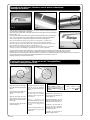
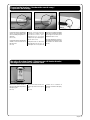
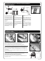
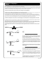
Assembling the ailerons / Monteren van de aileron scharnieren /
Montage des ailerons
Take one wing panel and remove the aileron (Pic. 1). Check carefully if all hinges are well glued
into the aileron by pulling firmly on the hinges.
Apply epoxy glue on both sides of all hinges and apply also epoxy glue in the slot of the aileron
torque rod (Pic. 2-3).
Place the aileron back into position ensuring that the hinges are fitted correctly into the hinge
slots. Leave a small gap of max. 0.5mm between wing and aileron. Remove immediately all
excess of epoxy glue (Pic. 4) Repeat this sequence also for the other wing panel.
Neem een vleugelhelft en demonteer het rolroer van de vleugel (Pic. 1). Verifieer of de
scharnieren in het rolroer goed verlijmd zijn door stevig aan de scharnieren te trekken.
Breng vervolgens 5 minuten epoxy aan op alle scharnieren aan beide zijden. Breng eveneens
epoxy lijm aan in de uitsparing van de rolroer aansturing (Pic. 2-3).
Monteer het rolroer terug aan de vleugel en laat een spleet van max. 0,5 mm. Verwijder alle
overtollige epoxy lijm onmiddellijk (Pic. 4) Herhaal dit voor de andere vleugelhelft.
Joining the wing halves / Monteren van de 2 vleugelhelften /
Préparation des panneaux d’aile
Apply epoxy glue on both sides
of one half of the wing joiner W18
(Drw. 1).
Apply also epoxy glue inside the
slot for the wing joiner W18
(Pic. 5).
Slide the wing joiner inside the
wing panel and move it several
times in and out to equaly distrib-
ute the glue.
Push the wing joiner into the slot
untill the end (Pic. 6).
Breng epoxy lijm aan op een halve
zijde aan de voor en achterkant
van de vleugelverbinding W18
(Drw. 1).
Breng eveneens epoxy lijm aan in
de sleuf waar de vleugel-
verbinding W18 ingeschoven
wordt (Pic. 5).
Monteer vervolgens de
vleugelverbinding W18 in de sleuf
en beweeg W18 enkele malen op
en neer om de lijm goed te
verdelen.
Druk de vleugelverbinding in de
vleugel tot deze niet meer verder
kan (Pic. 6).
W18
Pic. 1 Pic. 2
Pic. 3
Pic. 4
Pic. 5 Pic. 6
Drw. 1
Prenez un panneau d’aile et retirez l’aileron (Pic.1). Tirez fermement sur les charnières pour vérifier si elles sont bien collées.
Appliquez de la colle époxy de chaque côté des charnières ainsi que dans le logement de la commande d’aileron (Pic.2-3).
Installez l’aileron sur le panneau d’aile, vérifiez que toutes les charnières sont correctement placées dans leur logement, laissez un espace de
0,5mm entre l’aileron et le panneau d’aile. Retirez immédiatement tout excédant de colle (Pic. 4).
Répétez l’opération pour l’autre panneau d’aile.
Appliquez de la colle époxy sur
chaque face d’une moitié de la clé
d’aile W18 (Drw. 1)
Appliquez également de la colle
époxy dans le logement de la clé
d’aile du panneau d’aile (Pic.5)
Introduisez la clé d’aile dans le
panneau et tirez et poussez
quelques fois la clé d’aile afin de
bien répartir la colle.
Poussez la clé d’aile jusqu’au
fond du logement (Pic 6).

Skystar - 7
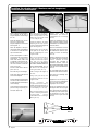
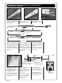
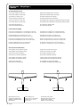
Joining the wing halves (Part 2) / Monteren van de 2 vleugelhelften (Deel 2) /
Assemblage de l’aile
Apply epoxy glue on both sides
of the other half of the wing joiner.
Apply also epoxy glue inside the
slot for the wing joiner W18.
Apply epoxy glue on both wing
ribs.
Assemble the 2 wing panels to-
gether and fix them with self ad-
hesive tape. Remove all excess
of epoxy glue immediately(Pic. 7).
Warning: Check carefully the di-
hedral of the wing (Drw 1a).
Breng epoxy lijm aan op de
andere zijde aan de voor en
achterkant van de vleugel-
verbinding W18.
Breng eveneens epoxy lijm aan in
de sleuf waar de vleugel-
verbinding W18 ingeschoven
wordt.
Breng epoxy lijm aan op de beide
vleugelribben.
Monteer vervolgens de 2
vleugelhelften tegen elkaar en
fixeer deze met kleefband.
Verwijder de overtollige epoxy lijm
onmiddellijk (Pic. 7).
Let op: Controleer of de
V-stelling juist is (Drw 1a).
Mounting the aileron servo holder / Monteren van de rolroerservo houder /
Montage du support du servo d’ailerons
Place the plywood aileron servo
holder over the servo slot in the
wing as shown in Pic 8.
Draw with a pen a line around the
servo holder.
Take the servo holder away and
cut with a sharp hobby knife 2mm
on the inside of the drawn line.
Remove the covering film in this
part. (Drw. 2)
Apply epoxy glue on the servo
holder and fit it back into the po-
sition.
Plaats het plaatje voor de
rolroerservo (W29) op de vleugel
zoals afgebeeld (Pic. 8).
Teken vervolgens met een pen
rond het plaatje om de omtrek van
het plaatje af te tekenen.
Snij vervolgens voorzichtig met
een scherp hobbymes 2 mm aan
de binnenzijde van de
afgetekende lijn.
Verwijder de folie. (Drw. 2)
Breng epoxy lijm aan op het
plaatje en lijm het op zijn plaats.
Pic. 7
Pic. 8
Drw. 2
Appliquez de la colle époxy sur
l’autre moitié de la clé d’aile.
Appliquez également de la colle
époxy dans le logement de la clé
d’aile.
Appliquez de la colle époxy sur
les faces internes des panneaux
d’aile.
Joignez les 2 panneaux et fixez-
lez avec du ruban adhésif.
Enlevez tout excédant de colle
immédiatement.
(Pic. 7)
Attention: Contrôlez
correctement le dièdre de l’aile
(Drw 1a).
Drw. 1a
Placez le support de servo en bois
sur le logement de servo de l’aile,
voir Pic 8.
Tracez à l’aide d’un feutre le con-
tour du support sur l’aile.
Enlevez le support et découpez à
l’aide d’un cutter 2mm à l’intérieur
de votre tracé, et enlevez le film de
recouvrement (Drw 2).
Appliquez de la colle époxy sur le
support servo et collez-le sur l’aile.

8 - Skystar
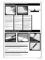
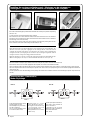
Assembling the elevator panel / Voorbereiden van het hoogteroer /
Assemblage du stabilisateur
Take the tailplane and remove the
elevator panel. Check carefully if
all hinges are well glued into the
elevator by pulling firmly on the
hinges.
Apply epoxy glue on both sides
of all hinges.
Place the elevator back into po-
sition ensuring that the hinges are
fitted correctly into the hinge
slots. Leave a small gap of max.
0.5mm between tailplane and el-
evator. Remove immediately all
excess of epoxy glue. (Pic. 10)
Mount the control horn on the el-
evator panel. (See Drw. 5-6)
Neem het stabilo en demonteer
het hoogteroer. Verifieer of de
scharnieren in het stuurvlak goed
verlijmd zijn door stevig aan de
scharnieren te trekken.
Breng vervolgens 5 minuten
epoxy aan op alle scharnieren aan
beide zijden.
Monteer het hoogteroer terug aan
het stabilo. Laat een spleet van
max. 0,5 mm. Verwijder
onmiddellijk alle overtollige epoxy
lijm. (Pic. 10)
Monteer vervolgens de stuurhevel
op het hoogteroer. (Zie Drw. 5-6)
Assembling the rudder panel / Voorbereiden van het richtingsroer
Assemblage de la dérive
Take the fin and remove the rud-
der panel. Check carefully if all
hinges are well glued into the rud-
der by pulling firmly on the hinges.
Apply epoxy glue on both sides
of all hinges.
Place the rudder back into posi-
tion ensuring that the hinges are
fitted correctly into the hinge
slots. Leave a small gap of max.
0.5mm between fin and rudder.
Remove immediately all excess of
epoxy glue. (Pic. 9)
Mount the control horn on the
rudder panel. (See Drw. 3-4)
Neem het richtingsroer en
demonteer het stuurvlak. Verifieer
of de scharnieren in het stuurvlak
goed verlijmd zijn door stevig aan
de scharnieren te trekken.
Breng vervolgens 5 minuten
epoxy aan op alle scharnieren aan
beide zijden.
Monteer het stuurvlak terug aan
het richtingsroer. Laat een spleet
van max. 0,5 mm. Verwijder
onmiddellijk alle overtollige epoxy
lijm. (Pic. 9)
Monteer vervolgens de stuurhevel
op het stuurvlak. (Zie Drw. 3-4)
M2X15
M2X15
TOP SIDE
Pic. 9 Drw. 3 Drw. 4
Pic. 10 Drw. 5 Drw. 6
Prenez la dérive et détachez la
gouverne de direction.
Tirez fermement sur les
charnières pour vérifier si elles
sont bien collées.
Appliquez de la colle époxy sur
chaque côté des charnières.
Insérez la gouverne dans la dérive
et vérifiez que les charnières sont
correctement installées. Laissez
un espace de 0,5mm entre la
dérive et la gouverne. Retirez
immédiatement tout excédant de
colle (Pic.9).
Montez le guignol sur la gouverne
de direction, voir Drw. 3-4.
Prenez le stabilisateur et détachez
la gouverne de profondeur.
Tirez fermement sur les
charnières pour vérifier si elles
sont bien collées.
Appliquez de la colle époxy sur
chaque côté des charnières.
Insérez la gouverne dans le
stabilisateur et vérifiez que les
charnières sont correctement
installées. Laissez un espace de
0,5mm entre le stabilisateur et la
gouverne. Retirez immédiatement
tout excédant de colle (Pic.10).
Montez le guignol sur la gouverne
de profondeur, (voir Drw. 5-6).

Skystar - 9
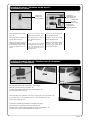
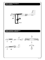
Mounting the wing dowels / Monteren van de houten dowels /
Montage des tourillons de fixation d’aile
Mount the 2 wooden dowels in
place and glue them into position
with epoxy glue.
(Pic. 14)
Monteer de houten dowels in de
romp en lijm deze vast met epoxy
lijm.
(Pic. 14)
Preparing the fuselage / Voorbereiden van de romp /
Préparation du fuselage
Cut open the slots for the tailplane
and fin. Use a sharp hobby knife
and cut carefully through the cov-
ering film.
(Pic. 11-12)
Cut open the slots for the wooden
dowels on the front and rear of
the wing seat.
(Pic. 13)
Maak de openingen waar het
richtingsroer en stabilo moeten
gemonteerd worden open.
Gebruik hiervoor een scherp
hobbymes en snij voorzichtig door
de folie. (Pic. 11-12)
Verwijder de folie voor de houten
elastiekhouders aan de voor- en
achterzijde van de romp.(Pic. 13)
Pic. 11 Pic. 12 Pic. 13
Pic. 14
Découpez sur l’arrière du fuselage
le film de recouvrement à l’endroit
du passage de la dérive et du
stabilisateur (Pic. 11-12).
Découpez également sur le fuse-
lage le film à l’endroit de passage
des tourillons de fixation d’aile
(Pic.13).
Installez les 2 tourillons et
sécurisez à l’aide de colle époxy
(Pic. 14).

10 - Skystar
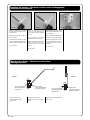
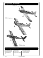
Installing the elevator panel / Monteren van het hoogteroer /
Installation du stabilisateur
Mark a centerline on the tailplane.
This centerline will be used to
align the tailplane on the fuselage
(Pic.15).
Slide the tailplane into the tail-
plane slot of the fuselage.
Align the tailplane as shown in the
drawing (Drw. 7).
When the tailplane is well posi-
tioned. Draw lines on the tailplane
as shown in Pic.16. Do this for the
top and bottom side.
Remove the tailplane. Cut with a
sharp hobby knife 1mm inside the
marked lines. DO NOT CUT
TRUE THE WOOD, ONLY THE
COVERING SHOULD BE RE-
MOVED. Remove the covering
film on the inside for a better ad-
hesion of the glue.
Do this for both sides of the tail-
plane. (Pic. 17)
Place the wing on the fuselage.
Apply epoxy glue to the exposed
wood on the tailplane.
Slide the tailplane into the taiplane
slot and use the marked lines for
a perfect alignment of the taiplane
to the fuselage.
Check from the front that the tail-
plane and wing are perfectly par-
allel. (Drw. 8) (Pic. 18)
Teken met een pen een lijn per-
fect in het midden van het stabilo.
Deze centerlijn dient voor het
uitlijnen van het hoogteroervlak
t.o.v. de romp (Pic.15).
Schuif het stabilo in de stabilo
uitsparing van de romp. Lijn het
hoogteroervlak uit zoals afgebeeld
op de tekening (Drw. 7).
Trek vervolgens met een pen aan
beide zijde van de romp alsook
aan de onderzijde lijnen op het
hoogteroervlak.
Neem het hoogteroervlak uit de
romp. Snij met een scherp
hobbymes 1mm binnen de lijn de
folie weg voor een betere
hechting van de lijm. NIET DOOR
HET HOUT SNIJDEN, ENKEL DE
FOLIE VERWIJDEREN. Doe dit
aan de boven en onderzijde van
het hoogteroervlak. (Pic. 17)
Plaats vervolgens de vleugel op
de romp.
Breng epoxy lijm aan op het
vrijgemaakte gedeelte van het
hoogteroervlak.
Schuif vervolgens het
hoogteroervlak in de romp en
gebruik de afgetekende lijnen op
het hoogteroervlak als referentie
voor de uitlijning t.o.v. de romp.
Neem vervolgens plaats voor het
toestel en verifieer goed dat het
hoogteroervlak perfect
horizontaal staat t.o.v. de vleugel.
(Drw. 8) (Pic. 18)
Pic. 15
Pic. 16
Pic. 17
Pic. 18
Drw. 7
Drw. 8
Tracez l’axe central du
stabilisateur, qui servira à
l’alignement sur le fuselage
(Pic.15).
Insérez le stabilisateur dans la
fente arrière du fuselage. Alignez
le stabilisateur comme indiqué sur
le dessin (Drw.7).
Quand le stabilisateur est bien
positionné, tracez sur les 2 faces
du stabilisateur à l’aide d’un stylo
à bille le contour du fuselage
(Pic. 16).
Retirez le stabilisateur, découpez
au cutter le film de recouvrement
1mm à l’intérieur de votre
tracé.NE PAS COUPER À
TRAVERS LE BOIS, SEUL LE
FILM DOIT ETRE RETIRE. Retirez
le film des 2 faces du stabilisateur
(Pic.17).
La colle adhère mieux sur le bois
et mal sur le film de recouvrement.
Fixez l’aile sur le fuselage avec
des élastiques.
Appliquez de la colle époxy sur
la zone en bois du stabilisateur
que vous venez de découvrir.
( appliquez sur les 2 faces).
Glissez le stabilisateur dans le
fuselage et utilisez les marquages
pour l’alignement sur le fuselage.
Contrôlez par des mesures que
le stabilisateur et l’aile sont
parfaitement alignés (Drw.8)
(Pic.18).

Skystar - 11
Installing the rudder / Monteren van het richtingsroer /
Installation de la dérive
Slide the fin into the fin slot of the
fuselage.
When the fin is well positioned. Draw
lines on the fin as shown in Pic. 19.
Do this for the left and right side.
Remove the fin. Cut with a sharp
hobby knife 1mm inside the marked
lines. Remove the covering film for a
better adhesion of the glue. DO NOT
CUT TRUE THE WOOD, ONLY THE
COVERING SHOULD BE REMOVED.
Do this for both sides of the fin.
(Pic. 20)
Apply epoxy glue to the exposed
wood on the fin.
Slide the fin into the fin slot. Make
sure that the fin is at a 90° angle to
the tailplane (Drw. 9)
Schuif het richtingsroer in de
uitsparing van de romp.
Teken met een pen een lijn op het
richtingsroervlak aan beide zijden
langsheen de romp
Snij met een scherp hobbymes 1mm
naast de lijn de folie weg voor een
betere hechting van de lijm. NIET
DOOR HET HOUT SNIJDEN, ENKEL
DE FOLIE VERWIJDEREN. Doe dit
aan de beide zijden van het
richtingsroervlak.
(Pic. 20)
Breng epoxy lijm aan op het
vrijgemaakte gedeelte alsook op de
plaatsen waar het richtingsroervlak de
romp raakt.
Schuif vervolgens het
richtingsroervlak in de romp en
verifieer goed dat het richtingsroer
haaks t.o.v. het hoogteroer staat.
(Drw. 9)
Installing main landing gear / Monteren van het landingsgestel /
Installation du train d’attérissage
Cut open the slot of the main landing gear with a sharp hobby knife (Pic.21).
Mount the 2 pre-bend undercarriage legs into position (Pic.22).
Place the plastic saddle clamps over the undercarriage legs. Drill 4 wholes with a 2mm drill(Pic.23).
Fix the plastic saddle clamps with the 4 supplied 2,9X13mm self-tapping screws (Pic.24).
Snij met een scherp hobbymes de uitsparing voor het landingsgestel uit (Pic.21).
Monteer de 2 verenstaal landingsbenen in de uitsparing (Pic.22).
Plaats de plastiekplaatjes over de landingsbenen en boor 4 gaatjes voor met een spiraalboor van
2mm (Pic.23).
Fixeer vervolgens de plastiek plaatjes met 4 zelftapschroeven van 2,9X13 mm.(Pic.24).
Pic. 19 Pic. 20
Drw. 9
Pic. 21
Pic. 22
Pic. 23
Pic. 24
Insérez la dérive dans le fuselage.
Quand elle est bien positionnée,
tracez une ligne sur les 2 côtés de la
dérive comme indiqué (Pic.19).
Retirez la dérive, découpez au
cutter le film de recouvrement
1mm à l’intérieur de votre tracé.
NE PAS COUPER À TRAVERS LE
BOIS, SEUL LE FILM DOIT ETRE
RETIRE. Retirez le film des 2
côtés de la dérive (Pic.20).
Appliquez de la colle époxy sur
la zone en bois de la dérive que
vous venez de découvrir.
(appliquez sur les 2 côtés).
Insérez la dérive dans le fuselage
et vérifiez avec une équerre
qu’elle est bien à 90° par rapport
au stabilisateur (Drw. 9).
Découpez au cutter le film de recouvrement à l’endroit du logement du train d’attérissage (Pic.21).
Installez les 2 jambes de train principal dans le logement (Pic.22).
Positionnez les 2 fixations en plastique sur le fuselage, marquez, percez 4 trous de 2 mm (Pic.23).
Vissez-les en place avec les vis à bois de 2,9x13mm fournies (Pic.24).

12 - Skystar
Installing the noseleg / Monteren van het voorste landingsgestel /
Installation du train avant
Slide the control arm over the
noseleg as shown and fix it with
a M3X6 screw.
Slide a plastic spacer on top of
the control arm.
Assemble the noseleg into the
holder and lock into position with
a brass collet and a M3X6 screw.
(Pic. 25-26-27)
Schuif de stuurarm over de
wielpoot zoals afgebeeld en
schroef deze vast met een M3X6
schroef.
Schuif vervolgens een platiek
afstandsbus over de wielpoot.
Monteer de wielpoot in de voorste
wielhouder en fixeer deze met een
messing stopper en een M3X6
schroef.
(Pic. 25-26-27)
Mounting the wheels / Monteren van de wielen /
Montage des roues
Fix the wheels on the
undercarriages as shown
(Drw. 10-11).
Bevestig de wielen zoals
afgebeeld op de tekening. (Drw.
10-11)
Plastic spacer
Kunststof afstandsbus
Entretoise plastique
Brass wheel collet
Messing wielstopper
Bague d’arrêt
Brass wheel collet
Messing wielstopper
Bague d’arrêt
Plastic spacer
Kunststof afstandsbus
Entretoise plastique
Drw. 10 Drw. 11
Pic. 25 Pic. 26
Pic. 27
Glissez le levier de contrôle sur la
jambe de train et bloquez -le avec
la vis M3x6mm.
Glissez l’entretoise en plastique
au-dessus du levier de contrôle.
Montez la jambe dans son sup-
port et maintenez en place avec
une bague d’arrêt et une vis
M3x6mm.
(Pic. 25-26-27)
Montez les roues comme illustré
(Drw. 10-11).

Skystar - 13
Assembling the fuel tank / Monteren van de brandstoftank /
Montage du réservoir
Assemble the fuel tank as shown.
Warning: the silicon tube with the
metal clunk need to be about 10
mm shorter than the length of the
fuel tank. The clunk need a 100%
free movement inside the tank in
all positions.
(Drw. 12)
Mount the fuel tank in the fuse-
lage. The rubber cap must fit into
the opening of the firewall. The
fuel tank can be held in place in-
side the fuselage with packing
foam. (Pic. 28)
Monteer de brandstoftank zoals
afgebeeld.
Let op: de slang met met de clunk
moet iets korter zijn dan de lengte
van de tank. De clunk moet in alle
posities vrij kunnen bewegen.
(Drw. 12)
Plaats de brandstoftank in de
romp. De rubber dop moet door
het gat van de motorspant komen.
De tank kan gefixeerd worden met
schuimrubber.
(Pic. 28)
Installing the engine / Monteren van de motor /
Installation du moteur
Place your engine on the motor mount as shown in Pic. 29 and drawing (Drw. 13).
Mark the mounting position of the engine using a sharp point.(Pic. 29)
Remove the engine and drill 4 holes of 3mm at the marked positions. (Pic. 30)
To mount the engine we use 4X M3X25 screws with washers and M3 nylstop nuts. (Pic. 31-32)
Plaats de motor op de motordrager zoals afgebeeld op foto Pic. 29 en tekening (Drw. 13).
Neem een puntslag en duid de gaten van de motor aan op de houten motordrager. (Pic. 29)
Neem de motor weg en boor 4 gaten op de aangeduide plaatsen met een spiraalboor van
3mm. (Pic. 30)
Voor het bevestigen van de motor gebruiken we 4X M3X25 schroeven met rondellen en M3
Nylstop moeren.(Pic. 31-32)
M3X20
TOP
Drw. 12
Pic. 28
Pic. 29
Pic. 30
Pic. 31
Pic. 32
Drw. 13
Assemblez le réservoir comme
illustré.
Attention: le tube silicone avec le
plongeur doit-être 10mm plus
court que la longueur du réservoir.
Le plongeur doit pouvoir bouger
dans toutes les positions
(Drw.12).
Installez le réservoir dans le fuse-
lage. Le capuchon du réservoir
doit entrer dans le logement
prévu. Le réservoir est Bloqué
dans le fuselage à l’aide de
mousse.(Pic. 28)
Installez le moteur sur le support comme montré (Pic.29) et illustration (Drw.13).
Utilisez une pointe pour marquer les endroits de perçage (Pic.29)
Enlevez le moteur et forez 4 trous de 3mm sur vos marques (Pic.30).
Fixez le moteur sur le support avec les 4 vis de M3x25mm, les rondelles M3 et les écrous
nylstop M3 (Pic. 31-32).

14 - Skystar
Assembling the push rods / Monteren van de stuurstangen /
Installation des commandes
Cut with a sharp hobby knife the
openings for the control rods as
shown in the pictures.
(Pic. 33-34-35)
Snij met een scherp hobbymes
de openingen voor de
stuurstangen vrij. (Pic. 33-34-35)
Assemble the push rods for the
elevator and rudder as shwon in
drawing. Use the plastic tubes
with a length of 480 mm. Do not
put on the plastic snap links yet.
The plastic snap links will be fit-
ted when the push rods are in
position.
(Drw. 14-15-16)
Monteer de stuurstangen voor het
hoogteroer en richtingsroer zoals
afgebeeld. Gebruik hiervoor de
kunststof buisjes van 480 mm. De
plastiek kwiklink moet nog niet
gemonteerd worden. De kwiklink
wordt gemonteerd als de
stuurstang op zijn plaats
geschoven wordt.
(Drw. 14-15-16)
640 mm
643 mm
Rudder - Richtingsroer - Direction
Elevator - Hoogteroer - Profondeur
Mount the plastic tube for the
throttle control rod as shown.
This plastic tube needs to be
glued into the firewall with a bit
of epoxy glue.(Drw. 18)
Mount the plastic tube for the
steerable front undercarriage as
shown with a bit of epoxy glue.
(Pic. 36) (Drw. 17)
Monteer het plastiek buisje voor
de gasstuurstang zoals
afgebeeld. Het plastiek buisje
wordt in de voorste motorspant
vastgelijmd met een beetje
epoxy lijm.(Drw. 18)
Monteer eveneens het plastiek
buisje voor de aansturing van
het neuswiel zoals afgebeeld en
fixeer met epoxy lijm.
(Pic. 36) (Drw. 17)
Plastic tube - Kunststof buisje - gaine
480 mm
Throttle tube
Buisje voor de carburator
Gaine vers le carburateur
Noseleg tube
Buisje voor het neuswiel
Gaine vers la roue AV
Firewall
Motorspant
Couple moteur
Pic. 33
Pic. 34
Pic. 35
Pic. 36
Drw. 14
Drw. 15
Drw. 16
Drw. 17
Drw. 18
Découpez avec un cutter le
passage des commandes.
(Pic. 33-34-35)
Assemblez les commandes de
profondeur et de direction comme
indiqué. Utilisez les gaines
plastiques d’une longueur de
480mm.
N’installez pas maintenant les
chapes, elles seront mises après.
(Drw. 14-15-16)
Montez la gaine pour la
commande du carburateur,
fixez-la au couple moteur avec
un peu de colle époxy.(Drw. 18)
Montez le gaine pour la
commande de la roue AV, fixez-
la avec un peu de colle époxy,
voir (Pic. 36) (Drw. 17)

Skystar - 15
Installing the servos / Monteren van de servo’s /
Installation des servos
Mount the aileron servo as shown
in Pic. 37.
Mount the 3 servos into the fuse-
lage as shown in Pic. 38.
Warning: the servos need to be
fixed with the rubber grommets,
brass bushings and the screws
which are supplied with your
servos.
Monteer de rolroerservo zoals
afgebeeld op de foto (Pic. 37).
Monteer de 3 servo’s in de romp
zoals afgebeeld op de foto
(Pic. 38).
Let op: de servo’s moeten steeds
bevestigd worden met de rub-
bers, messing busjes en de
schroeven die bij de servo’s
geleverd worden.
Installing the switch harness / Monteren van de schakelaar /
Installation de l’intérrupteur
Place the switch harness plate on the outside of the fuselage.
Mark with a pen the holes and cut-outs (Pic. 40).
Cut with a sharp hobby knife the openings in the fuselage (Pic. 41).
Mount the switch harness (Pic. 42).
Plaats het plaatje van de schakelaar op de romp en teken de gaten af met een pen.(Pic. 40)
Snij vervolgens met een scherp hobbymes de vorm van de schakelaar uit (Pic. 41).
Monteer de schakelaar (Pic. 42).
Aileron servo
Rolroer servo
Servo d’ailerons
Rudder servo
Richtingsroer servo
Servo de direction
Elevator servo
Hoogteroer servo
Servo de profondeur
Throttle servo
Gas servo
Servo de gas
Pic. 37
Pic. 38
Pic. 39
Pic. 40
Pic. 41
Pic. 42
Installez le servo d’ailerons
comme indiqué (Pic.37)
Installez 3 servos sur la platine
dans le fuselage (Pic.38)
Attention: Pour la fixation, utilisez
toujours les petits blocs
caoutchouc, les rivets et les vis
fournis avec les servos.
Positionnez la plaquette de l’intérrupteur sur l’extérieur du fuselage.
Marquez les trous et la découpe à l’aide d’une pointe (Pic. 40).
Découpez avec un cutter la fenêtre de passage du bouton d’intérrupteur (Pic. 41).
Percez les 2 trous de vis. Vissez l’intérrupteur en place (Pic. 42).

16 - Skystar
Installing the receiver and battery pack / Monteren van de ontvanger en
batterijpack / Installation de la batterie de réception et du récepteur
Place the receiver batterypack just behind the fuel tank and securely fix in position with packing
foam (Pic. 43).
Connect all servos to the appropriate receiver channels.
We recommand to use a servo extension lead (PL013.25) for the aileron servo. This extension
lead need to be connected to the aileron channel of the receiver. With the use of an extension
lead the wing can be removed easely.
Place the receiver in front of the servos and securely fix in position with packing foam (Pic.45).
Drill a small hole in the side of the fuselage for the aerial.(Pic. 46)
Plaats de batterij juist achter de brandstoftank en fixeer de batterij met schuimrubber.(Pic. 43)
Sluit alle servo’s aan op de juiste uitgangen van de ontvanger. Om de rolroerservo aan de
ontvanger aan te sluiten raden wij aan een verlengsnoer van ongeveer 20cm te gebruiken. Dit
verlengsnoer wordt op de uitgang van de rolroerservo op de ontvanger aangesloten. Met dit
verlengsnoer kan de vleugel eenvoudig gedemonteerd worden.
Plaats de ontvanger voor de servo’s en fixeer de ontvanger met voldoende schuimrubber (Pic.45).
Maak een klein gaatje in de romp voor de antennedraad naar buiten te voeren. (Pic. 46)
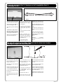
Steering modes / Stuurmode’s /
Mode de pilotage
To fly radio control models, 2 kind
of flying modes are used.
This will depend on your local fly-
ing club or instructor.
You can choose between mode
1 and mode 2 (Drw. 19-20).
Meestal worden er 2 soorten
mode’s gebruikt om te vliegen.
Dit hangt af meestal af wat er bij
u in de vliegclub of door uw
instructeur gebruikt wordt.
Ofwel gebruikt u mode 1 of mode
2 (Drw. 19-20).
MODE 1
MODE 2
Pic. 43 Pic. 45Pic. 44
Pic. 46
Drw. 19 Drw. 20
Placez la batterie de réception juste derrière le réservoir et bloquez sa position avec de la mousse (Pic.43)
Raccordez les servos sur les sorties appropriées du récepteur. (voir notice de votre télécommande).
Nous conseillons d’utiliser une allonge de 25cm (réf: PL013.25) entre le récepteur et le servo d’ailerons, cela facilite la mise en place de l’aile.
Placez le récepteur devant les servos et bloquez sa position avec de la mousse, il ne peut pas bouger en vol et doit être protégé des vibrations et
salissures (Pic.45).
Percez un petit trou sur le côté du fuselage pour le passage de l’antenne vers l’extérieur et fixez-la en fin de fuselage (ne jamais couper l’antenne).
(Pic.46).
Il existe 2 principaux mode de vol,
vous avez le choix d’utiliser le
Mode 1 ou Mode 2.
L’utilisation de l’un ou l’autre
dépend de votre localisation et/
ou de votre instructeur.
(Drw. 19-20).

Skystar - 17
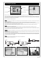
Connecting the push rods
Before you start to connect the push rods to the servos, you need to check that the servos are in their neutral position.
Turn-on your transmitter and receiver. The sticks and the trims on the transmitter have to be in the center position. If all sticks and trims are in the
center position, the arms on the servos have to be perfectly horizontal or vertical. If the servo horn is not perfectly horizontal or vertical aligned,
remove the servo horn and align it to the correct position.
Now you are ready to connect the push rods.
Rudder:
Remove the servo horn from the rudder servo. On the servo horn you need to mount the brass rod connector to connect the push rod from the
steerable noseleg (Drw. 22).
Slide the rudder push rod inside the plastic tube going to the rudder. Connect the end with the Z-bend to the rudder servo horn.
On the other end you can mount the plastic snap link and connect the plastic snap link to the rudder control horn. Adjust the length of the push
rod by turning on the plastic snap link till the rudder is straight (Pic. 47-50).
Slide the push rod from the steerable noseleg into the brass rod connector from the rudder servo and fix it with a M3X6 screw (Pic. 51).
Elevator:
Remove the servo horn from the elevator servo.
Slide the elevator push rod inside the plastic tube going to the elevator. Connect the end with the Z-bend to the elevator servo horn.
On the other end you can mount the plastic snap link and connect the plastic snap link to the elevator control horn. Adjust the length of the push
rod by turning on the plastic snap link till the elevator is level (Pic. 47-49).
Carburator:
Remove the servo horn from the throttle servo. On the servo horn you need to mount the brass rod connector to connect the push rod from the
carburator. (Pic. 47)
Slide the throttle push rod inside the plastic tube going to the carburator. Slide the push rod from the carburator into the brass rod connector from
the throttle servo and fix it with a M3X6 screw (Drw. 22).
When your throttle stick is in the idle position, the carburator should be slightly open (Drw. 20). When your throttle stick is in the full power position,
the carburator should be opened completely (Drw. 21). When you move your throttle stick to the idle position as well your trim completely down,
the carburator should be closed completely.
Ailerons:
Prepare 2 M2 push rods with a Z-bend with a plastic snap link on the threaded end.
Connect the push rods as shown in Pic. 48.
To the noseleg
To the carburator
To the elevator
To the rudder
Aileron servo
Elevator control horn Rudder control horn Noseleg
Pic. 47
Drw. 20
Pic. 48
Pic. 49
Pic. 50
Pic. 51
Drw. 21
Drw. 22

18 - Skystar
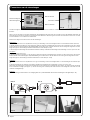
Connecteren van de stuurstangen
Voordat we beginnen met het aansluiten van de stuurstangen aan de servo’s moeten we controleren of de servo’s zich in de neutraal positie
bevinden.
Hiervoor moet u de zender en ontvanger aanschakelen. De stuurknuppels alsook de trims van de zender moeten in de middelste stand staan. Als
dit het geval is moeten de servoarmen mooi horizontaal of verticaal staan. Is dit niet het geval, schroef de servoarm dan los van de servo en verzet
de arm totdat deze mooi horizontaal of vertikaal staat.
Nu kunnen we beginnen met het monteren van de stuurstangen.
Richtingsroer:
Neem de servoarm van de servo. Op deze arm moet nog een stuurstang connector bevestigd worden voor het stuurbaar neuswiel. (Drw. 22)
Schuif de stuurstang in het buisje voor het richtingsroer. Sluit het einde met de Z-buiging aan de servoarm van de richtingsroerservo aan. Aan het
andere uiteinde van de stuurstang kan de plastiek kwiklink geschroefd worden en aan de stuurhevel van het richtingsroer aangesloten worden.
Regel de lengte van de stuurstang zo af dat het stuurvlak mooi recht staat (Pic. 47-50).
Schuif vervolgens de stuurstang van het stuurbaar neuswiel in het buisje en blokkeer de stuurstang met de stuurstang connector op de servo arm..
Hoogteroer:
Neem de servoarm van de servo.
Schuif de stuurstang in het buisje voor het hoogteroer. Sluit het einde met de Z-buiging aan de servoarm van de hoogteroerservo aan. Aan het
andere uiteinde van de stuurstang kan de plastiek kwiklink geschroefd worden en aan de stuurhevel van het hoogteroer aangesloten worden.
Regel de lengte van de stuurstang zo af dat het stuurvlak mooi recht staat. (Pic. 47-49)
Carburator:
Neem de servoarm van de servo. Op deze arm moet ,og een stuurstang connector bevestigd worden voor de stuurstang van de carburator (Pic.
47).
Schuif de stuurstang van de carburator in het buisje en blokkeer de stuurstang met de stuurstang connector op de servo arm.
Als de stick van het gas zich in de onderste positie bevindt, moet de carburator nog een klein beetje open zijn (Pic. 20). In de bovenste stick positie
moet de carburator volledig open zijn (Pic. 21). Als de stick terug in de onderste positie staat en de trim ook volledig naar onder staat, moet de
carburator volledig dicht zijn.
Rolroeren:
Maak 2 stuurstangen met M2 draad en een Z-buiging klaar met 2 plastiek kwiklinks. Monteer deze stuurstangen zoals afgebeeld (Pic. 48).
Naar het neuswiel
Naar de carburator
Naar het hoogteroer
Naar het richtingsroer
Rolroerservo
Hoogteroer stuurhevel Richtingsroer stuurhevel Neuswiel
Pic. 47
Drw. 20
Pic. 48
Pic. 49
Pic. 50
Pic. 51
Drw. 21
Drw. 22

Skystar - 19
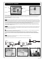
Raccordement des commandes
Avant de raccorder les commandes aux servos, vous devez vous assurez qu’ils sont en position neutre.
Pour cela, allumé votre émetteur et votre récepteur, placez les trims et sticks en position centrale (neutre), maintenant les palonniers sur les
servos doivent être parfaitement horizontaux ou verticaux. Si ce n’est pas le cas, dévissez la vis centrale du servo et otez le palonnier et
pivotez sur le crantage.
Maintenant vous êtes prêt pour raccorder les commandes.
Direction:
Enlevez le palonnier du servo de direction. Installez sur ce palonnier le connecteur de tringle pour la commande de roue avant, (voir Drw.22).
Glissez la tringle de commande dans la gaine jusqu’ à la gouverne de direction.Raccordez la terminaison en Z au palonnier de servo (au besoin
agrandissez le trou du palonnier, mais pas trop car il ne doit pas y avoir de jeu). Montez à l’autre extrémité de la tringle une chape plastique et
raccordez-la au guignol de direction. Attention, votre servo étant au neutre par conséquent votre gouverne de direction devrait l’être aussi. Si
ce n’est pas le cas, ajustez la longueur de la commande en vissant ou dévissant la chape plastique.(Pic.47-50).
Glissez la tringle de commande de roue avant dans la gaine, connectez l’extrémité en Z à la roue avant (vous devrez redémonter le train),
connectez l’autre extrémité au raccord de tringle que vous avez installé sur le palonnier de servo de direction. Ajustez pour que la roue soit
droite et serrez la vis M3x6 (Pic.47-51).
Profondeur:
Enlevez le palonnier du servo de profondeur. Glissez la tringle dans la gaine jusqu’à la gouverne de profondeur. Raccordez l’extrémité en Z au
palonnier de servo, à l’autre extémité vissez une chape plastique et connectez au guignol sur la gouverne de profondeur. N’oubliez pas de
contrôler et d’ajuster au besoin (Pic.47-49).
Gas:
Enlevez le palonnier du servo de gas.Installez sur ce palonnier un connecteur de tringle (Drw. 22) . Glissez la tringle dans la gaine jusqu’à la
commande du carburateur et raccordez les extrémités (Pic. 47).
Quand votre stick de commande de gas est en position de ralenti (position basse), le carburateur doit être un peu ouvert (Drw.20).
Quand votre stick de commande de gas est en position plein gas (position haute), le carburateur doit être ouvert au maximum (Drw.21).
Lorsque vous amenez votre stick de commande en position ralenti et que vous baissez en plus le trim, le carburateur doit être totalement
fermé.
Ailerons:
Utilisez les 2 petites tiges aux terminaisons filetées et en Z. Installez et raccordez comme indiqué Pic.48.
Contrôlez la position neutre, ajustez si besoin.
Sécurisez toutes les chapes plastiques en glissant de petits morceaux de tube silicone sur celles-ci.(Pic.49)
Roue avant
Au carburateur
Profondeur
Direction
Ailerons
Guignol de profondeur Guignol de direction Train avant
Pic. 47
Drw. 20
Pic. 48
Pic. 49
Pic. 50
Pic. 51
Drw. 21
Drw. 22
Tube silicone

20 - Skystar
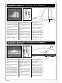
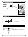
Connecting the fuel lines / Verbinden van de brandstofslangen /
Raccordement des durites à carburant
To the exhaust
Naar de uitlaat
Vers échappement
Fuel filler
Om te tanken
Pour le remplissage
To the carburator
Naar de carburator
Vers le carburateur
Pic. 52
Pic. 53
Spinner & Propeller / Spinner en propeller /
Cône d’hélice et hélice
Fixing the wing / Bevestiging van de vleugel /
Fixation de l’aile
Use rubber band to fix the wing on the fuselage (min.6pcs).
Gebruik elastieken voor het bevestigen van de vleugel op de romp
(min. 6 stuks).
Utilisez des élastiques plats et larges pour fixer l’aile sur le fuselage
(min.6 pcs).
To assembled the spinner see the drawing.
Stel de spinner samen zoals afgebeeld op de tekening.
Installez le cône d’hélice et l’hélice comme illustré sur le dessin.
(veillez a bien serrer l’écrou)
Rubber Band 125x10mm Ref: MA120
Seite wird geladen ...
Seite wird geladen ...
Seite wird geladen ...
Seite wird geladen ...
-
 1
1
-
 2
2
-
 3
3
-
 4
4
-
 5
5
-
 6
6
-
 7
7
-
 8
8
-
 9
9
-
 10
10
-
 11
11
-
 12
12
-
 13
13
-
 14
14
-
 15
15
-
 16
16
-
 17
17
-
 18
18
-
 19
19
-
 20
20
-
 21
21
-
 22
22
-
 23
23
-
 24
24


protech Skystar Benutzerhandbuch
- Kategorie
- Ferngesteuertes Spielzeug
- Typ
- Benutzerhandbuch
in anderen Sprachen
- English: protech Skystar User manual
- français: protech Skystar Manuel utilisateur
- Nederlands: protech Skystar Handleiding
Verwandte Artikel
-
protech Airblade Benutzerhandbuch
-
-
-
-
-
-
-
-
-