WALTHER PILOT PILOT WA 650 Bedienungsanleitung
- Kategorie
- Power-Feinsprühsysteme
- Typ
- Bedienungsanleitung

Betriebsanleitung / Operating Instructions
PILOT WA 650
Automatische Spritzpistole / Automatic Spray Guns

32
PILOT WA 650
Stand: Juni 2017
28
30
6
5
4
3
2
1
7
12
11
9
10
8
23
22
21
20
17
15
29
25
24
14
13
26
27
28
37
31
36
33
32
39
39
38
34
35
38
11
9
8
7
6
10
14
13
12
40
Seite 4 - 17
Page 18 - 31

54
EG / EU Konformitätserklärung
Wir, der Gerätehersteller, erklären in alleiniger Verantwortung, dass das Produkt in der
untenstehenden Beschreibung den einschlägigen grundlegenden Sicherheits- und
Gesundheitsanforderungen entspricht. Bei einer nicht mit uns abgestimmten Änderung
an dem Gerät oder bei einer unsachgemäßen Verwendung verliert diese Erklärung ihre
Gültigkeit.
Hersteller WALTHER Spritz- und Lackiersysteme GmbH
Kärntner Str. 18 - 30
D - 42327 Wuppertal
Tel.: +49(0)202 / 787 - 0
Fax: +49(0)202 / 787 - 2217
www.walther-pilot.de • e-mail: [email protected]
Typenbezeichnung Automatische Spritzpistole
PILOT WA 650 V 22 600
Verwendungszweck Verarbeitung spritzbarer Materialien
Angewandte Normen und Richtlinien
EG-Maschinenrichtlinien 2006/42/EG
2014/34/EU (ATEX Richtlinien)
EN ISO 12100
DIN EN 1953 DIN EN 13463-1
DIN EN 1127-1 DIN EN 13463-5
Spezifikation im Sinne der Richtlinie 2014/34/EU
Kategory 2 Gerätebezeichnung II 2 G c T 5
Tech.File,Ref.:
2418
Bevollmächtigt mit der Zusammenstellung der technischen Unterlagen:
Nico Kowalski, WALTHER Spritz- und Lackiersysteme GmbH, Kärntner Str. 18 - 30
D- 42327 Wuppertal
Besondere Hinweise :
Das Produkt ist zum Einbau in ein anderes Gerät bestimmt. Die Inbetriebnahme ist
so lange untersagt, bis die Konformität des Endproduktes mit der Richtlinie
2006/42/EG festgestellt ist.
Wuppertal, den 14. März 2017
Name: Torsten Bröker
Stellung im Betrieb: Leiter der Konstruktion und Entwicklung
Diese Erklärung ist keine Zusicherung von Eigenschaften im Sinne der Produkthaftung. Die Sicherheitshinweise
der Produktdokumentation sind zu beachten.
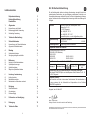
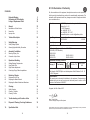
Inhaltsverzeichnis
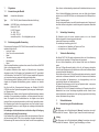
Explosionszeichnung 2
Konformitätserklärung 5
Ersatzteilliste 6
1. Allgemeines 8
1.1 Kennzeichnung des Modells 8
1.2 Bestimmungsgemäße Verwendung 8
1.3 Sachwidrige Verwendung 9
2. Technische Beschreibung 9
3. Sicherheitshinweise 9
3.1 Kennzeichnung der Sicherheitshinweise 9
3.2 Allgemeine Sicherheitshinweise 10
4. Montage 10
4.1 Spritzpistole befestigen 10
4.2 Versorgungsleitungen anschließen 11
5. Bedienung 11
5.1 Inbetrieb- und Außerbetriebsetzen 11
5.2 Spritzbildprobe erzeugen 11
5.3 Spritzbild verändern 12
5.4 Mängel des Spritzbildes beheben 13
6 Umrüstung / Instandsetzung 13
6.1 Luftkopf wechseln 13
6.2 Materialdüse wechseln 14
6.3 Materialnadel und Membrane wechseln 14
7. Reinigung 14
7.1 Sicherheitshinweise 14
7.2 Grundreinigung 15
7.3 Routinereinigung 16
8. Fehlersuche und -beseitigung 16
9. Entsorgung 16
10. Technische Daten 17
ppa.

76
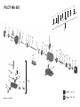
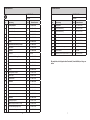
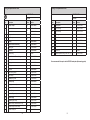
Ersatzteilliste
PILOT WA 650
V 22 600
Pos. Bezeichnung Stck. Ersatzteilnummer
1
Luftkopf komplett
1
V 10 151 30 039
2
Materialdüse 0,5 mm ø
1
V 10 151 41 053
Materialdüse 0,3 mm ø V 10 151 40 033
3
Innensechskantschraube
4
V 20 410 37 003
4
Pistolenvorderkörper
1
V 21 100 02 000
5
O-Ring
4
V 09 103 50 001
6
Pos. 40 (beinhaltet Pos. 6 - 14)
Materialnadel Vorderkörper kompl.
1 V 21 100 30 033
7
Stützscheibe
1
V 21 100 04 000
8 Membrane 1 V 21 100 05 000
9 Druckstück 1 2324340
10 Materialnadel Kolbengehäuse
1 V 21 100 19 003
11 Stützscheibe 1 V 21 100 07 000
12 Klemmbuchse 1 V 21 100 08 000
13 O-Ring 1 V 09 103 35 001
14 Nutring 1 V 09 220 25 000
15 Kolbengehäuse komplett 1 V 22 600 01 000
17 Kolben kompl. 1 V 22 600 21 000
20 Nadelfederteller 1 V 21 100 23 003
21 Nadelfeder 1 V 21 100 22 003
22 Mitnehmer kompl. 1 V 21 100 10 500
23 Sechskantmutter 1 V 20 900 15 003
24 Kolbenfeder 1 V 21 100 14 003
25 Gewindebuchse komplett 1 V 20 410 27 000
26 Nadelfeder 1 V 21 100 15 003
27 Regelkappe komplett 1 V 22 650 11 000
28 Adapter kompl. (Beinhaltet Pos. 31-39)
1 V 22 600 03 000
29 Rund-/Breitstrahlregelung kompl.
2 V 22 600 16 000
30 Nadelzentrierwerkzeug 1 V 21 100 50 000
Ersatzteilliste
PILOT WA 650
V 22 600
Pos. Bezeichnung Stck. Ersatzteilnummer
31
Pos. 28 (beinhaltet Pos. 31 - 39)
Adapterplatte
1
V 21 100 03 003
32
Steckverschraubung
1
V 66 001 53 304
33
Steckverschraubung
1
V 66 101 53 318
34
O-Ring
2
V 09 102 38 001
35
Schraube
2
V 21 100 03 303
36
O-Ring
2
V 09 104 13 001
37
Unterlegscheibe
2
V 20 679 85 000
38
Gerade Verschraubung
2
2342357
39
Überwurfmutter
2
2321490
40
Nadel-Rep.-Satz easy (Beinhaltet Pos. 6-14)
1
V 22 600 30 003
Wir empfehlen, alle fettgedruckten Ersatzteile (Verschleißteile) auf Lager zu
halten.

98
1 Allgemeines
1.1 Kennzeichnung des Modells
Modell: Automatische Spritzpistole
Type: PILOT WA 650 (Umlauf-Niederdruck-Membran Ausführung)
Hersteller: WALTHER Spritz- und Lackiersysteme GmbH
Kärntner Str. 18-30
D-42327 Wuppertal
Tel.: 0202 / 787-0
Fax:
0202 / 787-2217
www.walther-pilot.de • Email:[email protected]
1.2 Bestimmungsgemäße Verwendung
Die automatische Spritzpistole PILOT WA 650 dient ausschließlich der Verarbeitung
spritzbarer Medien wie z.B:
• Lacke und Farben
• Fette, Öle und Korrosionsschutzmittel
• Kleber
• Trennmittel
• Keramikglasuren
• Beizen
Wenn Sie andere Materialien verspritzen wollen, wenden Sie sich bitte an WALTHER
Spritz- und Lackiersysteme GmbH.
Die spritzbaren Materialien dürfen lediglich auf Werkstücke bzw. Gegenstände
aufgetragen werden. Die Temperatur des Spritzmaterials darf 80°C grundsätzlich
nicht überschreiten. Das Modell PILOT WA 650 ist keine handgeführte Spritzpistole
und muss deshalb an einer geeigneten Halterung befestigt werden.
Die bestimmungsgemäße Verwendung schließt auch ein, dass alle Hinweise und
Angaben der vorliegenden Betriebsanleitung gelesen, verstanden und beachtet
werden.
Das Gerät erfüllt die Explosionsschutz-Forderungen der Richtlinie 2014/34/EU
(ATEX) für die auf dem Typenschild angegebene Explosionsgruppe, Gerätekategorie,
und Temperaturklasse.
Beim Betreiben des Gerätes sind die Vorgaben dieser Betriebsanleitung unbedingt
einzuhalten. Die vorgeschriebenen Inspektions- und Wartungsintervalle sind einzu-
halten. Die Angaben auf den Geräteschildern bzw. die Angaben in dem Kapitel
technische Daten sind unbedingt einzuhalten und dürfen nicht überschritten werden.
Eine Überlastung des Gerätes muss ausgeschlossen sein. Das Gerät darf in explo-
sionsgefährdeten Bereichen nur nach Maßgabe der zuständigen Aufsichtsbehörde
eingesetzt werden.
Der zuständigen Aufsichtsbehörde bzw. dem Betreiber obliegt die Festlegung
der Explosionsgefährdung (Zoneneinteilung).
Es ist betreiberseitig zu prüfen und sicherzustellen, dass alle technischen Daten und
die Kennzeichnung gemäß ATEX mit den notwendigen Vorgaben übereinstimmen.
Bei Anwendungen, bei denen der Ausfall des Gerätes zu einer Personengefährdung
führen könnte, sind betreiberseitig entsprechende Sicherheitsmaßnahmen vorzuse-
hen.
Falls im Betrieb Auffälligkeiten erkannt werden, muss das Gerät sofort stillgesetzt
werden und es ist mit WALTHER Spritz- und Lackiersysteme GmbH Rücksprache zu
halten.
Erdung / Potentialausgleich
Es muss sichergestellt werden, dass die Spritzpistole separat oder in Verbindung mit
dem Gerät auf dem sie aufgebaut ist, ausreichend geerdet ist (maximaler Widerstand
10
6
Ω).
1.3 Sachwidrige Verwendung
Die Spritzpistole darf nicht anders verwendet werden, als es im Abschnitt
Bestimmungsgemäße Verwendung geschrieben steht.
Jede andere Verwendung ist sachwidrig.
Zur sachwidrigen Verwendung gehören z.B.:
• das Verspritzen von Materialien auf Personen und Tiere
• das Verspritzen von flüssigem Stickstoff.
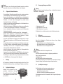
2 Technische Beschreibung
Das Modell PILOT WA 650 arbeitet vollautomatisch über eine Druckluftsteuerung
und wird über ein bauseitiges 3/2-Wege-Steuerventil angesteuert.
Die sonst übliche Nadelpackung wird bei diesem Modell durch eine Membrane
ersetzt.
Wird das 3/2-Wege-Steuerventil betätigt, tritt die für die Steuerung erforderliche
Druckluft in den Zylinderraum der Spritzpistole ein und öffnet den Zerstäuberluftkanal
und anschließend die Materialzufuhr.
Wird die Steuerluft durch das 3/2-Wege-Steuerventil wieder unterbrochen, entweicht
zunächst die im Kolbenraum befindliche Druckluft. Der Federdruck der Kolbenfeder
drückt anschließend die Materialnadel in ihre Ausgangsstellung zurück und
verschließt die Material- und Zerstäuberluftzufuhr.
Die Material-Durchflussmenge und die Form des Spritzstrahls (breit / rund) werden
mit Regelschrauben an der Pistole eingestellt.
Das Modell PILOT WA 650 (Niederdruck-Ausführung) mit Doppelanschluss für die
Materialzufuhr kann in eine Umlaufanlage eingebunden werden. Hiermit können
mehrere Spritzpistolen gleichzeitig durch die ringförmig angeordnete Umlaufleitung
mit dem Spritzmaterial versorgt werden.
3 Sicherheitshinweise
3.1 Kennzeichnung der Sicherheitshinweise
Warnung
Das Piktogramm und die Dringlichkeitsstufe „Warnung“ kennzeichnen eine mögli-
che Gefahr für Personen. Mögliche Folgen: schwere oder leichte Verletzungen.
Achtung
Das Piktogramm und die Dringlichkeitsstufe „Achtung“ kennzeichnen eine mögli-
che Gefahr für Sachwerte. Mögliche Folgen: Beschädigung von Sachen.

1110
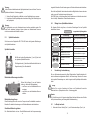
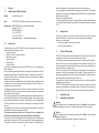
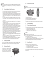
4.2 Versorgungsleitungen anschließen
Warnung
Achten Sie darauf, dass die Anschlüsse der Steuer- und Spritzluft nicht vertauscht
werden - Verletzungsgefahr.
1 = Materialanschluss G 1/8“
2 = Spritzluftanschluss ø 6 mm außen
3 = Steuerluftanschluss ø 4 mm außen
Die Spritzpistole ist nun vollständig montiert und kann in Betrieb gesetzt werden.
5 Bedienung
5.1 Inbetrieb- und Außerbetriebsetzen
Bevor Sie die Spritzpistole in Betrieb setzen können, müssen folgende
Voraussetzungen erfüllt sein:
• Der Steuerluftdruck muss an der Spritzpistole anstehen
• Der Zerstäuberluftdruck muss an der Spritzpistole anstehen
• Der Materialdruck muss an der Spritzpistole anstehen.
Achtung
Der Materialdruck darf nicht höher eingestellt sein als
• 2,0 bar,
da sonst kein funktionssicherer Betrieb der Spritzpistole gewährleistet ist.
Stellen Sie den Steuerluftdruck auf
• mindestens 5 bar,
damit die Spritzpistole in Betrieb gesetzt werden kann.
Sie können die Spritzpistole in und außer Betrieb setzen, indem Sie das 3/2-Wege-
Steuerventil betätigen (siehe Betriebsanleitung des Anlagenherstellers).
5.2 Spritzbildprobe erzeugen
Eine Spritzbildprobe sollte immer dann erzeugt werden, wenn
• die Spritzpistole zum ersten Mal in Betrieb gesetzt wird
• das Spritzmaterial ausgetauscht wird
• die Pistole zur Wartung oder Instandsetzung zerlegt wurde.
Die Spritzbildprobe kann auf ein Probewerkstück, Blech, Pappe oder Papier abge-
geben werden.
Hinweis
Das Piktogramm und die Dringlichkeitsstufe „Hinweis“ kennzeichnen zusätzliche
Informationen für das sichere und effiziente Arbeiten mit der Spritzpistole.
3.2 Allgemeine Sicherheitshinweise
• Die einschlägigen Unfallverhütungsvorschriften sowie die sonstigen anerkannten
sicherheitstechnischen und arbeitsmedizinischen Regeln sind einzuhalten.
• Benutzen Sie die Spritzpistole nur in gut belüfteten Räumen. Im Arbeitsbereich ist
Feuer, offenes Licht und Rauchen verboten. Beim Verspritzen leichtentzündlicher
Materialien (z. B. Lacke, Kleber, Reinigungsmittel usw.) besteht erhöhte
Gesundheits-, Explosions- und Brandgefahr.
• Schalten Sie vor jeder Wartung und Instandsetzung die Luft- und Materialzufuhr zur
Spritzpistole drucklos - Verletzungsgefahr.
• Halten Sie beim Verspritzen von Materialien keine Hände oder andere Körperteile
vor die unter Druck stehende Düse der Spritzpistole - Verletzungsgefahr.
• Um eine elektrostatische Aufladung zu vermeiden, muss die Halterung des
Spritzapparats geerdet sein.
• Richten Sie die Spritzpistole nicht auf Personen und Tiere - Verletzungsgefahr.
• Beachten Sie die Verarbeitungs- und Sicherheitshinweise der Hersteller von
Spritzmaterial und Reinigungsmitteln. Insbesondere aggressive und ätzende
Materialien können gesundheitliche Schäden verursachen.
• Tragen Sie im Arbeitsbereich der Spritzpistole einen Gehörschutz. Der erzeugte
Schallpegel der Spritzpistole von ca. 86 dB (A) kann einen Gehörschaden verursa-
chen.
• Die partikelführende Abluft ist vom Arbeitsbereich und Betriebspersonal fernzuhal-
ten. Tragen Sie dennoch vorschriftsgemäßen Atemschutz und vorschriftsgemäße
Arbeitskleidung, wenn Sie mit der Spritzpistole Materialien verarbeiten.
Umherschwebende Partikel gefährden Ihre Gesundheit.
• Achten Sie stets darauf, dass nach den Montage- und Wartungsarbeiten alle
Muttern und Schrauben fest angezogen sind.
• Verwenden Sie nur Original-Ersatzteile, da WALTHER Spritz- und Lackiersysteme
GmbH nur für diese eine sichere und einwandfreie Funktion garantieren kann.
• Bei Nachfragen zur gefahrlosen Benutzung der Spritzpistole wenden Sie sich bitte
an WALTHER Spritz- und Lackiersysteme GmbH, Wuppertal.
4 Montage
Die Spritzpistole mit Adapterplatte ist werkseitig komplett montiert. Bevor Sie die
Spritzpistole in Betrieb setzen können, sind die folgenden Tätigkeiten durchzuführen:
4.1 Spritzpistole befestigen
Befestigen Sie die Spritzpistole an einer
geeigneten, standsicheren Halterung.
Benutzen Sie hierzu die 6,2 mm ø Bohrung (1)
in der Adapterplatte und die beiden M5 Stifte
(2) zum Fixieren.
1
2
32
1

1312
Warnung
Achten Sie beim Inbetriebsetzen der Spritzpistole darauf, dass sich keine Person im
Spritzbereich befindet - Verletzungsgefahr
1. Setzen Sie die Spritzpistole in Betrieb, um eine Spritzbildprobe zu erzeugen
2. Kontrollieren Sie die Spritzbildprobe und verändern Sie ggf. die Einstellungen an
der Spritzpistole
Warnung
Die Spritzpistole muss nach Arbeitsende immer drucklos geschaltet werden. Die
unter Druck stehenden Leitungen können platzen und nahestehende Personen
durch das ausströmende Material verletzen.
5.3 Spritzbild verändern
Sie können an der Spritzpistole PILOT WA 650 durch die folgenden Einstellungen
das Spritzbild verändern:
Spritzluft einstellen
Materialdurchflussmenge einstellen
Materialdruck regulieren
Diese Einstellung können Sie nur an der Pumpe oder am Druckbehälter vornehmen.
Beachten Sie dabei die Anweisungen und Sicherheitshinweise des Herstellers.
Zerstäuberluftdruck regulieren
Der Zerstäuberluftdruck wird am Druckluft-Reduzierventil der Kompressoranlage
eingestellt. Beachten Sie die Anweisungen und Sicherheitshinweise des Herstellers.
Wenn Sie das Spritzbild über die bereits erwähnten Möglichkeiten hinaus verändern
wollen, muss die Spritzpistole umgerüstet werden.
WALTHER Spritz- und Lackiersysteme GmbH bietet dazu eine Vielzahl unterschied-
licher Luftkopf-/ Materialdüse-/ Nadel-Kombinationen an.
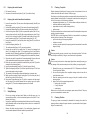
5.4 Mängel eines Spritzbildes beheben
Die folgende Tabelle zeigt Ihnen, mit welchen Einstellungen Sie das Spritzbild
beeinflussen können.
Spritzbildprobe Abweichung erforderliche Einstellung
Spritzbild ist in der Mitte zu
dick
• breitere Spritzstrahlform einstel-
len
Spritzbild ist an den Enden zu
dick
• rundere Spritzstrahlform einstel-
len
Spritzbild ist ziemlich grob-
tropfig
• Zerstäuberluftdruck erhöhen
Materialauftrag ist in der
Spritzbildmitte sehr dünn
• Zerstäuberluftdruck verringern
Spritzbild ist in der Mitte
gespalten
• Düsendurchmesser erhöhen
• Zerstäuberluftdruck verringern
• Materialdruck erhöhen
Spritzbild ist sehr ballig
• Materialdruck verringern
• Zerstäuberluftdruck erhöhen
6 Umrüstung / Instandsetzung
Die zum Spritzmaterial passende Luftkopf-/ Materialdüse-/ Nadel-Kombination bil-
det eine aufeinander abgestimmte Einheit - die Düseneinlage. Tauschen Sie immer
die komplette Düseneinlage aus, damit die gewünschte Spritzbildqualität erhalten
bleibt.
Warnung
Schalten Sie vor jeder Umrüstung die Steuer- und Zerstäuberluft sowie die
Materialzufuhr zur Spritzpistole drucklos - Verletzungsgefahr.
Hinweis
Zur Durchführung der im Folgenden aufgeführten Arbeitsschritte benutzen Sie bitte
die Explosionszeichnung am Anfang dieser Betriebsanleitung.
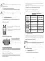
6.1 Luftkopf wechseln
1. Schrauben Sie den Luftkopf (Pos. 1) vom Pistolenvorderkörper (Pos. 4) ab.
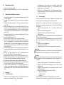
Drehen Sie die Kappe (1) aus der Grundein-
stellung (= Kerbe am Kolbengehäuse).
• nach innen, um den Materialdurchfluss zu
verringern
• nach außen, um den Materialdurchfluss zu
erhöhen.
1
1 2
Mit Hilfe der beiden Regelschrauben (1) und (2) lässt sich
ein optimales Spritzbild einstellen.
Die Regelschraube (1) beeinflusst die Breitstrahlluft und die
Regelschraube (2) die Rundstrahlluft.
angestrebtes Spritzergebnis

1514
• Im Arbeitsbereich ist Feuer, offenes Licht und Rauchen verboten. Beim
Verspritzen leichtentzündlicher Materialien (z. B. Reinigungsmittel) besteht
erhöhte Explosions- und Brandgefahr.
• Beachten Sie die Sicherheitshinweise des Reinigungsmittel-Herstellers.
Insbesondere aggressive und ätzende Reinigungsmittel können gesundheitli-
che Schäden verursachen.
7.2 Grundreinigung
Damit die Lebensdauer und die Funktion der Spritzpistole lange erhalten bleibt,
muss die Spritzpistole regelmäßig gereinigt und geschmiert werden.
Verwenden Sie zur Reinigung der Spritzpistole nur Reinigungsmittel, die vom
Hersteller des Spritzmaterials angegeben werden und die folgenden Bestandteile
nicht enthalten:
• halogenierte Kohlenwasserstoffe (z. B. 1,1,1, Trichlorethan, Methylen-Chlorid
usw.)
• Säuren und säurehaltige Reinigungsmittel
• regenerierte Lösemittel (sog. Reinigungsverdünnungen)
• Entlackungsmittel.
Die o.g. Bestandteile verursachen an galvanisierten Bauteilen chemische Reaktionen
und führen zu Korrosionsschäden.
Für Schäden, die aus einer derartigen Behandlung herrühren, übernimmt WALTHER
Spritz- und Lackiersysteme GmbH keine Gewährleistung. Reinigen Sie die
Spritzpistole
• vor jedem Farb- bzw. Materialwechsel
• mindestens einmal wöchentlich
• materialabhängig und je nach Verschmutzungsgrad mehrfach wöchentlich.
Achtung
Legen Sie die Spritzpistole nie in Lösemittel oder ein anderes Reinigungsmittel. Die
einwandfreie Funktion der Spritzpistole kann sonst nicht garantiert werden.
Achtung
Verwenden Sie zur Reinigung keine harten oder spitzen Gegenstände. Präzisionsteile
der Spritzpistole könnten sonst beschädigt werden und das Spritzergebnis ver-
schlechtern.
1. Zerlegen Sie die Pistole gemäß 6.2/ 6.3 Materialdüse und -nadel wechseln.
2. Reinigen Sie den Luftkopf und die Materialdüse mit einem Pinsel und dem
Reinigungsmittel.
3. Reinigen Sie alle übrigen Bauteile und den Pistolenkörper mit einem Tuch und
dem Reinigungsmittel.
4. Bestreichen Sie folgende Teile mit einem dünnen Fettfilm:
• Manschette des Kolbens
• O-Ring des Kolbens
• Nadelfeder
Verwenden Sie dazu ein säurefreies, nicht harzendes Fett und einen Pinsel.
Anschließend wird die Spritzpistole in umgekehrter Reihenfolge zusammengesetzt.
6.2 Materialdüse wechseln
1. Entfernen Sie zunächst den Luftkopf.
2. Entfernen Sie danach die Materialdüse (Pos. 2) (SW 7) vom Pistolenvorderkör-
per.
6.3 Materialnadel und Membrane wechseln
1. Lösen Sie die Schrauben (Pos. 35) und entfernen den Adapter kompl. (Pos. 28)
von der Spritzpistole.
2. Schrauben Sie die Regelkappe (Pos. 27) ab und entnehmen die Nadelfeder
(Pos. 26).
3. Schrauben Sie die Gewindebuchse (Pos. 25) ab und entnehmen die Kolbenfe-
der (Pos. 24).
4. Halten Sie den Mitnehmer (Pos. 22) mit einem Maulschlüssel (SW 5,5 mm)
fest, lösen und entfernen die Mutter (Pos. 23) mit einem Maulschlüssel (SW
5,5 mm) und ziehen den Mitnehmer (Pos. 22) ohne zu drehen nach hinten
heraus. Entnehmen Sie danach die Nadelfeder (Pos. 21) und den Nadelfeder-
teller (Pos. 20).
5. Lösen Sie die Schrauben (Pos. 3) und ziehen das Kolbengehäuse (Pos. 15) aus
dem Pistolenvorderkörper (Pos. 4).
6. Lösen Sie die Klemmbuchse (Pos. 12).
7. Die kompl. Nadel (Pos. 6 bis Pos. 12) kann jetzt getauscht werden.
8. Schrauben Sie das Nadelhinterteil (Pos. 10) ab, entfernen die Klemmbuchse
(Pos. 12), die Stützscheibe (Pos. 11), das Druckstück (Pos. 9) und anschließend
die Membrane (Pos. 8). Tauschen Sie die Membrane aus. Achten Sie darauf,
dass sich beim Einbau der Membrane die weiße PTFE-Schicht auf der Material-
seite (vorne) bendet.
9. Schrauben Sie das Nadelhinterteil auf die komplette Nadel auf. Achten Sie auf
den festen Sitz der Membrane zwischen den beiden Druckstücken (Pos. 7 und
Pos. 9).
10. Bevor die neue Nadel eingebaut wird muss das Nadelzentrierwerkzeug
(Pos. 30) in das Vorderteil (Pos. 4) eingeschraubt werden.
11. Legen Sie die kompl. Nadel (Pos. 6 bis Pos. 12) in das Vorderteil (Pos. 4) ein.
12. Ziehen Sie die Klemmbuchse (Pos. 12) im Vorderteil mit einer Kraft von 11 Nm
an. Danach schrauben Sie das Nadelzentrierwerkzeug wieder heraus.
13. Die Montage der restlichen Bauteile erfolgt in umgekehrter Reihenfolge.
14. Achten Sie bei der Montage des Kolbengehäuses (Pos. 15) auf das Vorderteil
(Pos. 4) darauf, dass die O-Ringe (Pos. 5) nicht verloren gehen.
15. Schrauben Sie die Regelkappe (Pos. 27), die als letztes aufgeschraubt wird,
soweit ein bis der Kappenrand zwischen den beiden Markierungsringen auf
dem Kolbengehäuse (Pos. 15) liegt. Dieses sorgt für ausreichend Druck auf der
Nadel.
7 Reinigung
7.1 Sicherheitshinweise
• Schalten Sie vor jeder Reinigung die Steuer- und Zerstäuberluft sowie die
Materialzufuhr zur Spritzpistole drucklos - Verletzungsgefahr.

1716
7.3 Routinereinigung
Bei regelmäßigen Farbwechseln oder (materialabhängig) nach Arbeitsende können
Sie die Spritzpistole auch reinigen, ohne diese dabei zerlegen zu müssen.
Hinweis
Reinigen und schmieren Sie die Spritzpistole regelmäßig gemäß Abschnitt 7.2
Grundreinigung. Sie erhalten so die sichere Funktion der Spritzpistole.
Um die Routinereinigung durchführen zu können, müssen Sie die folgenden
Arbeitsschritte durchführen:
1. Befüllen Sie den gesäuberten Materialbehälter mit einem geeigneten
Reinigungsmittel. Lediglich der Materialdruck muss an der Spritzpistole
anstehen. Das Reinigungsmittel sollte nicht zerstäubt werden.
2. Setzen Sie die Spritzpistole in Betrieb (siehe 5.1 Inbetrieb setzen).
3. Setzen Sie die Spritzpistole erst außer Betrieb, wenn diese nur noch klares
Reinigungsmittel verspritzt.
8 Fehlersuche und -beseitigung
Warnung
Schalten Sie vor jeder Wartung und Instandsetzung die Steuer- und Zerstäuberluft
sowie Materialzufuhr zur Spritzpistole drucklos -Verletzungsgefahr.
Fehler Ursache Abhilfe
Pistole tropft
Materialnadel oder
-düse verschmutzt
Materialnadel oder
-düse beschädigt
siehe 6.2/ 6.3 Materialnadel oder -düse
ausbauen und reinigen
siehe 6.2/ 6.3 Materialnadel oder -düse
austauschen
Pistole öffnet nicht Steuerluft zu niedrig Steuerluftdruck erhöhen auf min. 4,5 bar
Material tritt an der
Leckagebohrung aus
Membrane ist undicht
Klemmbuchse
(Pos. 12) ist lose
siehe 6.3 Membrane austauschen
Klemmbuchse mit Maulschlüssel (SW10)
etwas anziehen
Stoßweiser oder flat-
ternder Spritzstahl
zu wenig Material im
Materialbehälter
Material auffüllen (siehe Betriebs-
anleitung des Anlagenherstellers)
9 Entsorgung
Die bei der Reinigung und Wartung anfallenden Materialien sind den Gesetzen und
Vorschriften entsprechend sach- und fachgerecht zu entsorgen.
Warnung
Beachten Sie insbesondere die Hinweise des Herstellers der Spritz- und
Reinigungsmittel. Unachtsam entsorgtes Material gefährdet die Gesundheit von
Mensch und Tier.
10 Technische Daten
Düsengrößen: 0,3 / 0,5 mm ø
Gewicht: 645 g
Anschluss:
Zerstäuberluft 6 mm ø außen
Steuerluft 4 mm ø außen
Materialzufuhr G 1/8“
Druckbereiche:
Steuerluft mind. 5 bar
Materialdruck max. 2 bar
Zerstäuberluft max. 8 bar
max. Betriebstemperatur
der Spritzpistole 80 °C
Schallpegel
(gemessen in ca. 1 m
Abstand zur Spritzpistole) 86 dB (A)
Technische Änderungen vorbehalten.

1918
EC / EU Declaration of Conformity
We, the manufacturers of the equipment, hereby declare under our sole responsibility
that the product(s) described below conform to the essential safety requirements. This
declaration will be rendered invalid if any changes are made to the equipment without
prior consultation with us.
Manufacturer WALTHER Spritz- und Lackiersysteme GmbH
Kärntner Str. 18 - 30
D - 42327 Wuppertal
Tel.: +49(0)202 / 787 - 0
Fax: +49(0)202 / 787 - 2217
www.walther-pilot.de • e-mail: [email protected]
Type Designation Automatic Spray Gun
PILOT WA 650 V 22 600
Intended purpose Processing of sprayable media
Applied Standards and Directives
EU-Mechanical Engineering Directives 2006/42/EC
2014/34/EU (ATEX Directives)
EN ISO 12100
DIN EN 1953 DIN EN 13463-1
DIN EN 1127-1 DIN EN 13463-5
Specification according 2014/34/EU
Category 2 Part marking II 2 G c T 5
Tech.File,Ref.:
2418
Authorized with the compilation of the technical file:
Nico Kowalski, WALTHER Spritz- und Lackiersysteme GmbH, Kärntner Str. 18 - 30
D- 42327 Wuppertal
Special remarks :
The named product is intended for installation in other equipment. Commissioning is
prohibited until such time as the end product has been proved to conform to the
provision of the Directives 2006/42/EC.
Wuppertal, the 14th of March 2017
Name: Torsten Bröker
Position: Manager, Design and Development
This Declaration does not give assurance of properties in the sense of product liability. The safety instructions
provided in the product documentation must be observed at all times.
Contents
Exploded Drawing 2
Declaration of CE-Conformity 19
Listing of Replacement Parts 20
1. General 22
1.1 Identification of Model Version 22
1.2 Normal Use 22
1.3 Improper Use 23
2. Technical Description 23
3. Safety Warnings 23
3.1 Safety Warting Symbols 23
3.2 Generally Applicable Safety Precautions 24
4. Assembly / Installation 24
4.1 Mounting of Spray Gun 24
4.2 Connection of Input Lines 25
5. Operational Handling 25
5.1 Starting/Stopping Requirements 25
5.2 Spray Pattern Test 25
5.3 Spray Pattern Adjustments 26
5.4 Correcting of Spray Pattern Imperfections 27
6 Retooling / Repairs 27
6.1 Replacement of Air Cap 27
6.2 Replacing the Material Nozzle 28
6.3 Replacing the Material Needle and Membrane 28
7. Cleaning 28
7.1 Safety Warnings 28
7.2 Cleaning - Complete 29
7.3 Cleaning - Routine 29
8. Trouble shooting and Corrective Action 30
9. Disposal of Cleaning / Servicing Substances 30
10. Specification Data 31
p.p.

2120
Listing of Replacement Parts
PILOT WA 650
V 22 600
Item Description Piece Parts No.
1
Air Cap compl.
1
V 10 151 30 039
2
Material Nozzle 0,5 mm ø
1
V 10 151 41 053
Material Nozzle 0,3 mm ø V 10 151 40 033
3
Hexagon socket screw
4
V 20 410 37 003
4
Front Body
1
V 21 100 02 000
5
O-Ring
4
V 09 103 50 001
6
Pos. 40 (contains Pos. 6 - 14)
Material Needle Front Body
1 V 21 100 30 033
7
Backing disc
1
V 21 100 04 000
8 Membrane 1 V 21 100 05 000
9 Pressure ring 1 2324340
10 Material Needle Piston Casing
1 V 21 100 19 003
11 Backing disc 1 V 21 100 07 000
12 Clamping bush 1 V 21 100 08 000
13 O-Ring 1 V 09 103 35 001
14 Lip Seal 1 V 09 220 25 000
15 Piston Casing compl. 1 V 22 600 01 000
17 Piston compl. 1 V 22 600 21 000
20 Needle spring collar 1 V 21 100 23 003
21 Needle spring 1 V 21 100 22 003
22 Driving tenon compl. 1 V 21 100 10 500
23 Hexagonal Nut 1 V 20 900 15 003
24 Piston Spring 1 V 21 100 14 003
25 Threaded Ring compl. 1 V 20 410 27 000
26 Needle Spring 1 V 21 100 15 003
27 Regulating Cap compl. 1 V 22 650 11 000
28 Adapter compl. (contains items 31-39)
1 V 22 600 03 000
29 Round / wide jet control compl.
2 V 22 600 16 000
30 Needle centring tool 1 V 21 100 50 000
Listing of Replacement Parts
PILOT WA 650
V 22 600
Item Description Piece Parts No.
31
Pos. 28 (contains Pos. 31 - 37)
Adapterplate
1
V 21 100 03 003
32
Push-in-fitting
1
V 66 001 53 304
33
Push-in-fitting
1
V 66 101 53 318
34
O-Ring
2
V 09 102 38 001
35
Screw
2
V 21 100 03 303
36
O-Ring
2
V 09 104 13 001
37
Washer
2
V 20 679 85 000
38
Straight union
2
2342357
39
Sleeve nut
2
2321490
40
Needle-repair-set easy (contains Pos. 6-14)
1
V 22 600 30 003
It is recommended to keep in stock all BOLD-faced parts (fast wearing parts).

2322
1 General
1.1 Identification of Model Versions
Models: Automatic Spray Gun
Type: PILOT WA 650 (Circulating low-pressure membrane version)
Manufacturer: WALTHER Spritz- und Lackiersysteme GmbH
Kärntner Str. 18-30
D-42327 Wuppertal
Tel.: 0202 / 787-0
Fax:
0202 / 787-2217
www.walther-pilot.de • Email:[email protected]
1.2 Normal Use
The automatic spray gun PILOT WA 650 is exclusively designed for use with spra-
yable material types and grades such as:
• paints and lacquers
• greases, oils and corrosion preventives
• adhesive compounds
• Separating agent
• ceramic glazes
• pickling solutions
To spray other materials please contact WALTHER Spritz- und Lackiersysteme
GmbH, Wuppertal.
Please note that sprayable material may only be applied to work pieces and/or simi-
lar items. The temperature of the sprayed material must generally not exceed 80°C.
The PILOT WA 650 model is no hand-guided spray gun and needs to be fastened
therefore with a suitable holder.
The term normal use also implies that any and all safety warnings, operational hand-
ling details, etc., as stated in these operating instructions, must be carefully read,
understood and duly complied with.
This equipment complies with the explosion protection requirements of Directive
2014/34/EU (ATEX) for the explosion group, equipment category and temperature
class indicated on the type plate.
When using the equipment, the requirements specified in these Operating Instructions
must be observed at all times. The technical data indicated on the equipment rating
plates and the specifications in the chapter „Technical Data“ must be complied with
at all times and must not be exceeded. An overloading of the equipment must be
ruled out.
The equipment may be used in potentially explosive atmospheres only with the
authorisation of the relevant supervisory authority.
The relevant supervisory authority or the operator of the equipment are
responsible for determining the explosion hazard (zone classification).
The operator must check and ensure that all technical data and the marking of the
equipment in accordance with ATEX are compliant with the necessary requirements.
The operator must provide corresponding safety measures for all applications in
which the breakdown of the equipment might lead to danger to persons.
If any irregularities are observed while the equipment is in operation, the equipment
must be put out of operation immediately and WALTHER Spritz- und Lackiersysteme
GmbH must be consulted.
Grounding / Equipotential Bonding
You must ensure that the spray gun is properly earthed (grounded) either separately
or in connection with the equipment with which it is being used (maximum resistance
10
6
Ω).
1.3 Improper Use
This spray gun shall not be used for purposes other than set forth in the above
Chapter Normal Use. Any other form of use and/or application is prohibited.
Improper use is for example:
• spraying of material onto persons and animals
• spraying of liquid nitrogen, etc.
2 Technical Description
The PILOT WA 650 model works fully automatically via compressed air control and
is selected by a 3/2-way control valve provided by the customer.
The otherwise customary needle pack is replaced by a membrane with this model.
When the 3/2-way control valve is triggered, the compressed air required by the
control enters into the cylinder chamber of the spray gun and opens the atomizer air
channel and finally the material supply.
If the control air through the 3/2-way valve is interrupted again, the compressed air
remaining in the piston compartment will first escape. The spring pressure of the
piston spring subsequently pushes the material needle back to its original position,
closes the material supply and finally the atomizer air.
The material flow rate and the shape of the spray jet (wide / round) is adjusted with
regulating screws on the gun.
The PILOT WA 650 model (low-pressure version) with dual connector for material
supply can be integrated into a circulating system. This allows for the simultaneous
supply of several spray guns through the circular ring line with spraying material.
3 Safety Warnings
3.1 Safety Warning Symbols
Warning
This pictograph and the accompanying warning note „Warning“ indicate possible
risks and dangers for yourself. Possible consequences: Injuries of any kind.
Caution
This pictograph and the accompanying warning note „Caution“ indicate possible
damage to equipment.
Possible consequences: Damage to equipment, workpieces, etc.

2524
4.2 Connection of Input Lines
Warning
Make sure not to confuse the control and atomizing air connections -risk of injury.
1 = Material inlet fitting G 1/8“
2 = Atomizing air inlet fitting outside-diameter 6 mm
3 = Control air inlet fitting outside-diameter 4 mm
The spray gun is now properly installed and connected and ready for operation.
5 Operational Handling
5.1 Starting / Stopping Requirements
The following requirements must be met before taking this spray gun into operation:
• control air must be available at the gun
• atomizing air must be availabe at the gun
• material pressure must be availabe at the gun.
Caution
The material pressure shall not exceed
• 2 bar, as, otherwise, the functional reliability of the spray gun will suffer.
Adjust the control air pressure to
• at least 5 bar, in order to operate the spray gun.
The operation of the spray gun can be started/stopped by way of the 3/2-way control
valve (see the Operating Instructions of the plant systems manufacturer).
5.2 Spray Pattern Test
Spray pattern tests should be performed whenever:
• the spray gun is taken into operation for the first time
• the spraying medium is changed
• the spray gun was taken apart for servicing or repairs.
The spray pattern can be tested using a work piece sample, a sheet of metal, card-
board or paper.
Notice
This pictograph and the accompanying note „Notice“ indicate additional and useful
information to help you handling the spray gun with even greater confidence and
efficiency.
3.2 Generally Applicable Safety Precautions
• It is important that all applicable accident prevention directives as well as industri-
al safety and health rules and regulations are duly complied with.
• Use this spray gun in well ventilated rooms. Open fires, naked lights and smoking
are prohibited in the working area. Spraying of readily flammable media such as
paints, lacquers, cleaning agents, etc., causes a potential health, explosion and
fire risk.
• Prior to any servicing and repair work: Make sure that the spray gun is in unpres-
surized condition, i.e. all air and material inputs must be shut off - if not, imminent
risk of injury.
• Keep your hands and other extremities away from the front of the spray gun
- imminent risk of injury.
• The holder of the spraying unit must be grounded to prevent electrostatic charging.
• Never point the spray gun at persons or animals - imminent risk of injury.
• It is important that all processing specifications and safety warnings issued by the
manufacturers of spraying and cleaning media are duly complied with. Especially
aggressive and corrosive media can cause personal health problems.
• Wear suitable hearing protections while working with the spray gun. Spray guns
produce sound levels of up to 86 dB (A), which may cause hearing defects.
• Air-borne particles must be kept away from the working area and personnel. Wear
proper respiratory protection masks and protective overalls when working with
spraying media. Air-borne particles represent a health hazard.
• Check that nuts and screws are tightened properly after performing servicing and
repair work.
• Make sure you use original WALTHER Spritz- und Lackiersysteme GmbH replace-
ment parts designed for functional reliability and efficiency.
• Should you have any questions concerning the safe operation of the spray gun,
please contact WALTHER Spritz- und Lackiersysteme GmbH, Wuppertal.
4 Assembly / Installation
This spray gun with adaptor plate is delivered in completely assembled condition.
Before taking the spray gun into operation perform the following preparations:
4.1 Mounting of Spray Gun
Install the gun in a suitable and stable
mounting device. For this purpose use
the dia. 6.2 mm ø hole (1) in the adapter
plate and the two M5 pins (2) for fixing.
1
2
1
32

2726
Warning
Make sure that nobody is present in the spraying zone when the gun is started
- imminent risk of Injury.
1. Start the gun to produce a spray pattern sample
2. Inspect the sample and readjust the settings of the gun as may be required
Warning
It is important to remember that the spray gun must be relieved of all pressures
whenever work is terminated. Lines left in pressurized condition could burst, with
their contents likely to injure anybody present nearby.
5.3 Spray Pattern Adjustments
The spray pattern of the spray gun PILOT WA 650 can be adjusted as follows:
Adjusting the jet pattern
Adjustment of the material flow rate
Adjustment of the Material Pressure
This adjustment can only be made at the controls of the pump or the material pres-
sure tank. Please comply with the operating instructions and safety warnings issued
by the manufacturers concerned.
Adjustment of the Atomizing Air Pressure
The atomizing air pressure is adjusted at the air pressure reducing valve of the com-
pressor system. Please comply with the operating instructions and safety warnings
issued by the manufacturer.
If you wish to change the spraying pattern beyond the adjustments outlined so far,
you must retool the spray gun.
WALTHER Spritz- und Lackiersysteme GmbH offers a great variety of air control
head/-material control nozzle/ needle combinations for this purpose.
5.4 Correcting of Spray Pattern Imperfections
The following table shows what to do to correct a spray pattern.
Spray pattern test Deviation Required adjustment
Spray pattern is split in the centre • setting a wider spray pattern
Spray pattern is too thick at the
ends
• Setting a more rounded spray
pattern
The spray pattern shows rather
large droplets
• Increase the nozzle air pres-
sure
Material application in the centre
of the spray pattern is very thin
• Decrease the nozzle air pres-
sure
Spray pattern is split in
the centre
• Increase the nozzle diameter
• Reduce nozzle air pressure
• Increase material pressure
Spray pattern is very spherical
• Reduce material pressure
• Increase nozzle air pressure
6 Retooling / Repairs
Combinations of air control head, material control nozzle and needle, designed to
match specific spraying media tpyes and grades, form a unit - namely the nozzle
insert assembly. In order maintain the desired spray-finish quality standard always
replace the complete nozzle insert assembly.
Warning
Prior to retooling: Make sure that the spray gun is in unpressurized condition, i.e. all
air and material inputs must be shut off - if not, imminent risk of injury.
Notice
In order to perform the following procedures please use the drawing at the beginning
of these operating instructions.
6.1 Replacement of Air Cap
1. Unscrew the air cap (item 1) from the front body (item 4).
Turn cap (1) from the standard position
(= notch mark on the piston housing)
• to the inside in order to decrease the mate-
rial flow rate.
• to the outside in order to increase the mate-
rial flow rate.
1
1 2
An optimum spray pattern can be adjusted by using adju-
sting screws (1) and (2).
The adjusting screw (1) regulates the wide jet, the adjusting
screw (2) the round jet.
desired spray result

2928
7.2 Cleaning - Complete
Regular cleaning and lubrication of the spray gun has to be performed, in order to
increase the service life and the function of the spray gun.
Clean the gun only with cleaning solutions recommended by the manufacturer of the
spraying material used at the time. It is important to make sure that cleaning soluti-
ons do not contain any of the following constituents:
• halogenated hydrocarbons (e.g. 1,1,1-trichloroethane, methylene chloride, etc.)
• acids and acidiferous cleaning solutions
• regenerated solvents (so-called cleaning dilutions)
• paint removers.
The above constituents cause chemical reactions with the electroplated components
resulting in corrosion damage.
WALTHER Spritz- und Lackiersysteme GmbH is not responsible for any damages
resulting from such treatment. Clean the spray gun
• prior to each change of the spraying medium
• at least once a week
• as often as may be required by the spraying medium handled and the resultant
degree of fouling.
Caution
Never immerse the spray gun in solvent or any other cleaning solution. The functio-
nal reliability and efficiency of the gun can otherwise not be guaranteed.
Caution
Do not use any hard, pointed or sharp-edged objects when cleaning the spray gun.
Any damage of the precision-made parts are likely to affect your spraying results.
1. Dismantle the spray gun in accordance with 6.2/ 6.3 Replacement of Material
Control Nozzle and Needle.
2. Use a soft brush together with a compatible cleaning sulotion to clean the air
control head and nozzle.
3. Clean the remaining parts and the spray gun body with a suitable cloth and
cleaning solution.
4. Apply a thin film of the appropriate grease to the:
• sealing collar of the piston
• O-ring of the piston
• needle spring
Make sure to use a non-acidic, non-resinogenic grease and a soft brush. The spray
gun is then reassembled in reverse order.
7.3 Cleaning - Routine
The spray gun need not necessarily be dismantled for cleaning if and when the
spraying medium is changed in regular intervals or upon termination of work (depen-
ding on the material used).
6.2 Replacing the material nozzle
1. First remove the air cap.
2. Now remove the material nozzle (item 2) (size 7) from the front body.
6.3 Replacing the material needle and membrane
1. Loosen the screws (item 35) and remove the adapter assembly (item 28) from
the spray gun.
2. Unscrew the regulating cap (item 27) and remove the needle spring (item 26).
3. Unscrew the threaded ring (item 25) and remove the piston spring (item 24).
4. Hold the driving tenon (item 22) with an open-ended spanner (size 5.5 mm),
loosen and remove the nut (item 23) with an open-ended spanner (size 5.5 mm)
and pull out the driving tenon (item 22) toward the back without turning it. Re-
move the needle spring (Pos. 21) and the needle spring collar (Pos. 20).
5. Loosen the screws (item 3) and pull the piston casing (item 15) from the front
body (item 4).
6. Loosen the clamping bush (item 12).
7. The needle assembly (items 6 to 12) can now be replaced.
8. Unscrew the rear part of the needle (item 10), remove the clamping bush
(item 12), the backing disc (item 11), the pressure ring (item 9) and then the
membrane (item 8). Replace the membrane. Pay attention during installation of
the membrane that the white PTFE coating points to the material side (forward).
9. Screw the rear part of the needle onto the needle assembly. Ensure a rm seat
of the membrane between the two pressure rings (items 7 and 9)
10. Before the new needle is installed the needle centring tool (item 30) must be
screwed into the front part (item 4).
11. Insert the needle assembly (items 6 to 12) into the front part (item 4).
12. Tighten the clamping bush (item 12) in the front part with a torque of 11 Nm. Now
unscrew the needle centring tool again.
13. The assembly of the remaining components takes place in reverse order.
14. Make sure when mounting the piston casing (item 15) on the front part (item 4)
that the O-rings (item 5) will not be lost.
15. Screw down the regulating cap (item 27), which is screwed on last, far enough
until the edge of the cap rests between the two marking rings on the piston
casing (item 15). This ensures adequate pressure on the needle.
7 Cleaning
7.1 Safety Warnings
• Prior to any servicing and repair work: Make sure that the spray gun is in
unpressurized condition, i.e. all air and material inputs must be shut off - if not,
imminent risk of injury.
• No open fires, naked light and smoking allowed in the work area. When spraying
readily flammable media such as cleaning solutions, there is an increased risk
of fire and explosion.
• Observe the safety warnings issued by the manufacturer. Aggressive and
corrosive media represent risks and hazards to personal health.

3130
Notice
Clean and lubricate the spray gun frequently in accordance with Chapter 7.2
Cleaning - Complete. This will ensure functional reliability of the spray gun.
The following requirements must be met before the routine cleaning work can be
performed:
1. The material tank must be clean and then be filled with a compatible cleaning
solution. Material pressure has to be available at the spray gun. The cleaning
solution should not be sprayed.
2. Take the spray gun into operation (see 5.1 Starting the Spray Gun).
3. Do not stop the spray gun until clear cleaning solution emerges from the nozzle.
8 Troubleshooting and Corrective Action
Warning
Prior to any servicing and repair work: Make sure that the spray gun is in unpressu-
rized condition, i.e. all air and material inputs must be shut off - if not imminent Risk
of Injury.
Fault Cause Corrective Action
Gun is dripping
Material control nozzle
or needle fouled
Material control nozzle
or needle damaged
see 6.2/ 6.3 Removing Material Control
Nozzle or Needle and cleaning
see 6.2/ 6.3 Replacing Material Control
Nozzle or Needle
Gun fails to open Control air pressure too
low
Increaese control air pressure to at least 4,5
bar
Material leaks from
leakage boring
Membrane leaking
Clamping bush
(Item. 12) is loose
see 6.3 Replacing the membrane
Slightly tighten the clamping bush with the
open-ended spanner (size 10)
Spray jet pulsating
or unsteady
Level in material tank
too low
Top-up material level (see operating instruc-
tions of plant systems manufacturer)
9 Disposal of Cleaning / Servicing Substances
Disposal of any such substances must be in accordance with all applicable local and
national regulations, directives and laws.
Warning
Pay special attention to all processing specifications and safety warnings issued by
the manufacturers of spraying and cleaning media. The improper disposal of any
toxic waste material represents a serious threat to the environment, i.e. to the health
of mankind and animal life.
10 Specification Data
Nozzle Sizes: 0,3 / 0,5 mm ø
Weight: 645 g
Connections:
Atomizing Air 6 mm ø außen
Control Air 4 mm ø außen
Material Inlet G 1/8“
Pressure Ranges:
Control Air Pressure mind. 5 bar
Material pressure max. 2 bar
Atomizing Air max. 8 bar
max. Operating
Temperature of Spray gun 80 degs. C
Sound Level (measured at
a distance of 1 m from the
spray gun) 86 dB (A)
Right to effect technical changes reserved.

Das WALTHER PILOT-Programm
• Hand-Spritzpistolen
• Automatik-Spritzpistolen
• Niederdruck-Spritzpistolen
(System HVLP)
• Materialdruckbehälter
• Drucklose Behälter
• Rührwerk-Systeme
• Airless-Geräte und Flüssigkeitspumpen
• Materialumlaufsysteme
• Kombinierte Spritz- und Trockenboxen
• Absaugsysteme mit
Trockenabscheidung
• Absaugsysteme mit Nassabscheidung
• Trockner
• Zuluft-Systeme
• Atemschutzsysteme und Zubehör
The WALTHER PILOT Programme
• Hand-Held Spray Guns
• Automatic Spray Guns
• Low Pressure Spray Guns
(System HVLP)
• Material Pressure Tanks
• Nonpressurized Tanks
• Agitator Systems
• Airless Equipment and Transfer Pumps
• Material Circulation Systems
• Combined Spraying and Drying Booths
• Dry Back Overspray Extraction Systems
• Wet Back Overspray Extraction
Systems
• Dryers
• Ventilation Systems
• Protective Respiratory Systems and
Accessory Items
Walther Spritz- und Lackiersysteme GmbH
Kärntner Straße 18 -30
.
D-42327 Wuppertal
T +49 202 787-0
.
F +49 202 787-2217
info@walther-pilot.de
.
www.walther-pilot.de
Technische Änderungen und Irrtümer vorbehalten. © WALTHER PILOT 08/2017
-
 1
1
-
 2
2
-
 3
3
-
 4
4
-
 5
5
-
 6
6
-
 7
7
-
 8
8
-
 9
9
-
 10
10
-
 11
11
-
 12
12
-
 13
13
-
 14
14
-
 15
15
-
 16
16
-
 17
17


WALTHER PILOT PILOT WA 650 Bedienungsanleitung
- Kategorie
- Power-Feinsprühsysteme
- Typ
- Bedienungsanleitung
in anderen Sprachen
Verwandte Artikel
-
WALTHER PILOT V 20 340 Bedienungsanleitung
-
-
-
-
-
-
-
-
-