
Sicherheitstechnik GmbH
Montage- und Betriebsanleitung
Zentralbatteriesystem
CPS 220 / 20 / J-SV / J-SKÜ
CPS 220 / 64 / J-SV / J-SKÜ
Mounting- and Operating Instructions
Central Battery System
CPS 220 / 20 / J-SV / J-SKÜ
CPS 220 / 64 / J-SV / J-SKÜ


3
CPS 220/64/SV Montage- und Betriebsanleitung
CPS 220/64/SV Mounting and Operating Instructions
Inhalt
1. Allgemeine Hinweise 6
1.1. Symbolerklärung 6
1.2. Haftung und Gewährleistung 6
1.3. Ersatzteile 6
1.4. Entsorgung 6
1.5. Fehlerbeseitigung 6
2. Sicherheitshinweise 7
2.1. Bedienungsanleitung 7
2.2. Reparaturen 7
3. Transport und Lagerung 7
3.1. Kontrolle bei Anlieferung 7
3.2. Lagerung 7
4. Produktbeschreibung 8
4.1. CPS 220 / 64, CPS 220 / 20, CPUS 220 / 64 8
4.1.1. Aufbau der CPS 220/20 und CPS 220/64 10
4.2. CPUSB 220 / 64 / 16,
CPUSB 220 / 64 / 8 – 1,
CPUSB 220 / 64 / 8 – 9,
CPUSB 220 / 64 / 1 – 2A,
CPUSB 220 / 64 / 1 – 4A 13
4.2.1. Aufbau der CPUSB - Systeme 14
4.3 CPUSB 220 / 64 / 1 – 2x2,5A/24V 15
4.3.1. Aufbau 15
4.4 CPUSB 220 / 64 / 24V 16
5. Technische Daten 17
5.1. CPS 220 / 64, CPS 220 / 20, CPUS 220 / 64 17
5.2 CPUSB 220 / 64 / 16,
CPUSB 220 / 64 / 8 – 1,
CPUSB 220 / 64 / 8 – 9,
CPUSB 220 / 64 / 1 - 2A,
CPUSB 220 / 64 / 1 – 4A
CPUSB 220 / 64 / 1 - 2,5A / 24V 21
5.3 CPUSB 220 / 64 / 24V 22
6. Aufstellung, Anschluss 23
6.1. Montage 23
6.2. Batterie 24
6.2.2. 2 Batterieschränke mit 1 Strang
á 18 Blöcke 26
6.2.3. 2 Batterieschränke mit 2 Strängen
á 18 Blöcke 26
6.2.4.Batteriemontage auf Batteriegestell 27
6.2.5. Batterieschränke 2000mmm 27
6.3. Elektrischer Anschluss 27
6.3.1. Systemaufbau 27
6.3.2. CPS 220 / 20 …, CPS 220 / 64 …,
CPUS 220 / 64 …, CPUSB 220 / 64 / 16,
CPUSB 220 / 64 / 8 … 28
6.3.3. CPUSB 220 / 64 / 1 … 33
6.3.4. CPUSB 220 / 64 / 24V 36
Contents
1. General information 6
1.1. Explanation of symbols 6
1.2. Liability and warranty 6
1.3. Spare parts 6
1.4. Disposal 6
1.5. Correction of faults 6
2. Safety instructions 7
2.1. Operating instructions 7
2.2. Repairs 7
3. Transport and storage 7
3.1. Examination on delivery 7
3.2. Storage 7
4. Product description 8
4.1 CPS 220/64, CPS 220/20, CPUS 220/64 8
4.1.1. Layout CPS 220/20 and CPS 220/64 10
4.2 CPUSB 220/64/16,
CPUSB 220/64/8–1,
CPUSB 220/64/8–9,
CPUSB 220/64/1–2A,
CPUSB 220/64/1–4A 13
4.2.1. Layout CPUSB 14
4.3 CPUSB 220 / 64 / 1 – 2,5A 15
4.3.1. Design 15
4.4 CPUSB 220/64/24 V 16
5. Technical data 17
5.1. CPS 220/64, CPS 220/20, CPUS 220/64 17
5.2 CPUSB 220/64/16,
CPUSB 220/64/8–1,
CPUSB 220/64/8–9
CPUSB 220/64/1–2A,
CPUSB 220/64/1–4 A
CPUSB 220 / 64 / 1 - 2,5A / 24V 21
5.3 CPUSB 220/64/24 V 22
6. Assembly, connection 23
6.1. Assembly 23
6.2. Battery 24
6.2.2. 2 battery cabinets with 1 battery set
18 blocks each 26
6.2.3. 2 battery cabinets with 2 battery sets
18 blocks each 26
6.2.4. Mounting on battery rack 27
6.2.5. 2000 mm battery cabinets 27
6.3. Electrical connection 27
6.3.1. System structure 27
6.3.2. CPS 220/20 …, CPS 220/64 …,
CPUS 220/64 …, CPUSB 220/64/16,
CPUSB 220/64/8 … 28
6.3.3. CPUSB 220/64/1 … 33
6.3.4. CPUSB 220/64/24 V 36

4
CPS 220/64/SV Montage- und Betriebsanleitung
CPS 220/64/SV Mounting and Operating Instructions
4
6.3.5. Zusätzliche Komponenten 39
6.3.5.1. RIF 5 39
6.3.5.2. Batteriemanagementsystem BCS 43
6.3.5.3. LSA 3 / LSA 8.1 47
6.3.5.4. Dreiphasenüberwachungen 50
6.3.5.5. LOMO 53
6.3.5.6. Fernmeldetableau – MTB 54
6.3.5.7. CPS-MTB 55
6.3.5.8. INOWEB 56
6.3.5.9. Phasenauswahlschaltung – PAS 56
7. Inbetriebnahme 57
7.1. Überprüfung der Verbindungen 57
7.2. Isolationsmessung 57
7.3. Ausschalten des Zentralbatteriesystems 58
7.4. Einschalten des Zentralbatteriesystems 58
8. Programmierung des CPS 220-Systems mit
Standardsteuerteil 59
8.1. Allgemeines 59
8.2. Testmenü 60
8.2.1. Funktionstest starten 60
8.2.2. Betriebsdauertest starten 60
8.2.3. Learn-Mode 60
8.2.4. Tiefentladeschutz prüfen 61
8.2.5. Isolationstesteinrichtung prüfen 61
8.2.6. Funktionstest abbrechen 61
8.2.7. Betriebsdauertest abbrechen 62
8.3. Info 62
8.3.1. Geräteinformationen 62
8.3.2. Störungs Info 64
8.3.3. Prüfbuch 65
8.4. Programmierung 66
8.4.1. Datum und Uhrzeit 66
8.4.2. Programmierung 67
9. Programmierung des CPS 220 - Systems mit
Komfortsteuerteils 77
9.1. Allgemeines 77
9.1.1. Aktualisierung der SD- Karte 78
9.1.2. Hilfetexte 78
9.2. Funktionstest starten / abbrechen 79
9.3. Info-Menü - Abfrage von Informationen 79
9.3.1. Geräte Info 80
9.3.2. Prüfbuch 81
9.3.3. Störungsausdruck 81
9.3.4. Stromkreisinformationen 82
9.3.5. Batterie- Info 84
9.3.6. DPÜ- Info 85
9.3.7. Komponenten- Info 85
6.3.5. Additional components 39
6.3.5.1. RIF 5 39
6.3.5.2. Battery management system BCS 43
6.3.5.3. LSA 3/LSA 8.1 47
6.3.5.4. Three-phase monitors (DPÜs) 50
6.3.5.5. LOMO 53
6.3.5.6. Remote mimic panel — MTB 54
6.3.5.7. CPS-MTB 55
6.3.5.8. INOWEB 56
6.3.5.9. Phase selector switch — PAS 56
7. Commissioning 57
7.1. Checking the connections 57
7.2. Insulation measuring 57
7.3. De-energise the central battery system 58
7.4. Energising the central battery system 58
8. Programming the CPS 220 system with
standard controller 59
8.1. General 59
8.2. Test menu 60
8.2.1. Running a function test 60
8.2.2. Starting battery duration test 60
8.2.3. Learn mode 60
8.2.4. Checking deep discharge protection 61
8.2.5. Checking insulation testing device 61
8.2.6. Cancelling a function test 61
8.2.7. Cancelling battery duration test 62
8.3. Info 62
8.3.1. Device information 62
8.3.2. Failure info 64
8.3.3. Logbook 65
8.4. Programming 66
8.4.1. Date and time 66
8.4.2. Programming 67
9. Programming the CPS 220 system with
comfort controller 77
9.1. General 77
9.1.1. Updating the SD card 78
9.1.2. Help texts 78
9.2. Running/cancelling a function test 79
9.3. Info menu — Requesting information 79
9.3.1. Device info 80
9.3.2. Logbook 81
9.3.3. Failure printout 81
9.3.4. Circuit info 82
9.3.5. Battery info 84
9.3.6. DPÜ info 85
9.3.7. Component info 85

5
CPS 220/64/SV Montage- und Betriebsanleitung
CPS 220/64/SV Mounting and Operating Instructions
9.4. Programmierung des CPS 220 Systems 88
9.4.1. Geräte- Programmierung 89
9.4.2. Zielort 91
9.4.3. Platzbelegung 91
9.4.4. Stromkreisprogrammierung 92
9.4.5. DPÜ/B 95
9.4.6. Module 96
9.5. Testmenü 99
9.5.1. Automatischer Funktionstest 100
9.5.2. Automatischer Betriebsdauertest 100
9.5.3. Learn Mode 100
9.5.3.1 Learn-Mode SKÜ-Stromkreise 100
9.5.4. Betriebsdauertest (BT) starten 101
9.5.5. ISO – Test 101
9.5.6. Tiefentladeschutz (TES) prüfen 101
9.6. Einstellungen 102
9.6.1. RTG-Adresse 102
9.6.2. Datum und Uhrzeit 102
9.6.3. USB 103
9.6.4. Netzwerkeinstellungen 106
9.7. INOWEB 107
9.7.1 Bedienung 107
9.7.2. Störungsausdruck 108
9.7.3. Externe Verknüpfungen 109
10. Programmierung CPUSB 220/64/24 111
10.1. Bedienung und Menüstruktur 111
10.2. „Testmenü“ 112
10.3. „Programmierung“ 112
10.4. „Informationen“ 116
10.5 Block. Aufheben 117
11. Prüfungen 117
11.1 Erstprüfungen 117
11.2. Wiederkehrende Prüfungen der
elektrischen Anlagen für Sicherheitszwecke 117
11.3. Batterieinspektion und –überwachung 119
11.4. Protokolle zu wiederkehrenden Prüfungen 119
Anhang
A. Dokumentation 120
B. Leitungslängen 120
C. Kundendienst 120
Prüfung auf Leuchtenfehler 120
Softwareversion 121
D. Softwarestand 121
Index 122
9.4. Programming the CPS 220 system 88
9.4.1. Device programming 89
9.4.2. Destination 91
9.4.3. Position assignment 91
9.4.4. Circuit programming 92
9.4.5. DPÜ/B 95
9.4.6. Modules 96
9.5. Test menu 99
9.5.1. Automatic function test 100
9.5.2. Automatic battery duration test 100
9.5.3. Learn mode 100
9.5.3.1 Learn mode SKÜ circuits 100
9.5.4. Start battery duration test (DT) 101
9.5.5. ISO test 101
9.5.6. Test deep discharge protection (TES) 101
9.6. Settings 102
9.6.1. RTG address 102
9.6.2. Date and time 102
9.6.3. USB 103
9.6.4. Network settings 106
9.7. INOWEB 107
9.7.1 Operation 107
9.7.2. Failure printout 108
9.7.3.1. Configuring external links 109
10. Programming CPUSB 220/64/24 111
10.1. Operation and menu structure 111
10.2. "Test menu" 112
10.3. "Programming" 112
10.4. "Info" 116
10.5 Device block 117
11. Tests 117
11.1 Initial tests 117
11.2. Recurring safety tests on electrical systems 117
11.3. Battery inspection and monitoring. 119
11.4. Protocols for repeat tests 119
Appendix 118
A. Documentation 120
B. wire lengths 120
C. Customer Service 120
Check for luminaire failures 120
Software version 121
D. Software version 121
Index 122

6
CPS 220/64/SV Montage- und Betriebsanleitung
CPS 220/64/SV Mounting and Operating Instructions
6
1. General information
1.1. Explanation of symbols
This symbol highlights important information
in the mounting and operating instructions
that also concerns safety. Failure to follow
the instructions may result in physical injury
or breakage!
Instructions marked by a yellow icon provide
important information. Please read these very
carefully.
This icon provides additional information.
1.2. Liability and warranty
INOTEC does not accept any responsibility or liability
whatsoever for damage or consequential damage caused
by:
• Failure to operate devices according to their intended use
• Failure to follow instructions relating to safe operation
• The use of unauthorised or unsuitable components in
conjunction with the emergency lighting system
• Faulty installation
• Opening the device
1.3. Spare parts
Defective components must only be replaced with
original INOTEC spare parts. We cannot guarantee that
safety requirements are fully met if parts other than these
are used. No warranty, service or liability claims will be
acknowledged if unsuitable spare parts are used.
The use of defective spare parts may result in mal-
function or cause the system to fail entirely.
1.4. Disposal
Batteries and electronic components supplied by
INOTEC can be returned to INOTEC or should be
disposed of in accordance with the national guide-
lines and regulations governing the disposal of
used batteries and electronic components.
1.5. Correction of faults
Whenever a fault associated with connected lumi-
naires is corrected, a function test must be carried
out to reset the fault indication.
see 8.2.1. Running a function test on page 60
see 9.2. Running/cancelling a function test on page 79
1. Allgemeine Hinweise
1.1. Symbolerklärung
Sicherheitsrelevante Informationen sind durch
nebenstehendes Symbol gekennzeichnet. Eine
Nichtbefolgung der Anweisungen kann zu Per-
sonenschäden oder defektem Gerät führen!
Hinweise liefern wichtige Informationen und
sind mit einem gelben Symbol markiert. Bitte
lesen Sie diese sehr aufmerksam.
Dieses Symbol macht Sie auf zusätzliche Infor-
mationen aufmerksam.
1.2. Haftung und Gewährleistung
INOTEC übernimmt keine Gewährleistung oder Haftung
für Schäden oder Folgeschäden, die entstehen durch
• Nicht bestimmungsgemäßen Gebrauch
• Nichteinhaltung von Vorschriften für den sicheren
Betrieb
• Betrieb von nicht zugelassenen oder ungeeigneten
Komponenten am Notlichtsystem
• Bei fehlerhafter Installation
• Bei Eingriff in das Gerät
1.3. Ersatzteile
Defekte Bauteile dürfen nur gegen INOTEC-Original-
Ersatzteile ausgetauscht werden. Nur bei diesen Teilen
gewährleisten wir, dass Sie die Sicherheitsanforderungen
im vollen Umfang erfüllen. Garantie-, Service- und Haft-
pflichtansprüche erlöschen bei Verwendung nicht geeig-
neter Ersatzteile.
Der Einsatz von fehlerhaften Ersatzteilen kann zu
fehlerhaftem Betrieb oder einem nicht funktionie-
rendem System führen.
1.4. Entsorgung
Von INOTEC gelieferte Batterien und Elektronikbau-
teile können an INOTEC zurückgegeben werden
oder sind gemäß den nationalen Richtlinien und
Vorschriften für die Entsorgung von Alt-Batterien
und Elektronikbauteilen zu entsorgen.
1.5. Fehlerbeseitigung
Nach jeder Fehlerbeseitigung der angeschlossenen
Leuchten muss ein Funktionstest ausgelöst werden,
um den angezeigten Fehler zu löschen.
siehe 8.2.1. Funktionstest starten - Seite 60
siehe 9.2. Funktionstest starten / abbrechen - Seite 79

7
CPS 220/64/SV Montage- und Betriebsanleitung
CPS 220/64/SV Mounting and Operating Instructions
2. Safety instructions
Installation should only be carried out by electri-
cians qualified and trained.
The device must not be used for anything other than its
intended purpose and only in a perfect and undamaged
condition.
When installing and operating this device, please follow
your national safety and accident prevention regulations
at all times.
Before carrying out any work on the device, in particular
when replacing components, always disconnect the sys-
tem from the power source (mains and battery)!
see 7. Commissioning on page 57
2.1. Operating instructions
Always read the mounting and operating instruc-
tions before installing and commissioning the
device. These instructions contain important infor-
mation on the safety, use and maintenance of the device,
and will protect you and prevent damage to the system.
2.2. Repairs
Any repairs which need to be carried out or which
involve opening the device must ONLY be carried out by
personnel authorised to do so by INOTEC. The guarantee
becomes invalid if unauthorised personnel work on the
system.
3. Transport and storage
3.1. Examination on delivery
Please examine the device carefully at the point of receipt
to ensure complete delivery and that no external damage
exists. Please inform the carrier immediately if there are
any signs of damage — we regret that we are unable to
acknowledge complaints submitted after this point.
3.2. Storage
Until assembly, please observe the following regarding
storage of the device:
• Do not store in the open air
• Do store in a dry, dust-free environment
The following applies to batteries that have already been
fitted:
• Batteries must not be stored for more than 3 months
without being charged
• If the mains supply is interrupted for an extended
period of time, the battery circuit must be disconnected
by removing the battery fuse in accordance with the
operating instructions
see 7. Commissioning on page 57
• Charge the batteries for at least 24 hours before carrying
out the initial function test
2. Sicherheitshinweise
Die Installation darf nur durch Elektrofachkräfte
erfolgen.
Das Gerät ist bestimmungsgemäß und nur im einwand-
freien, unbeschädigten Zustand zu betreiben.
Für die Installation und den Betrieb dieses Gerätes sind
die nationalen Sicherheits- und Unfallverhütungsvor-
schriften zu beachten.
Vor Arbeiten an dem Gerät, insbesondere beim Austausch
von Baugruppen, ist die Anlage spannungsfrei zu schal-
ten (Netz- und Batteriespannung)!
siehe 7. Inbetriebnahme - Seite 57
2.1. Bedienungsanleitung
Lesen Sie vor der Montage und Inbetriebnahme
die Montage- und Betriebsanleitung. Sie gibt wich-
tige Informationen für die Sicherheit, den
Gebrauch und die Wartung des Gerätes. Dadurch schüt-
zen Sie sich und verhindern Schäden am Gerät.
2.2. Reparaturen
Eventuelle Reparaturen oder Eingriffe dürfen
ausschließlich durch INOTEC autorisierte Personen
vorgenommen werden. Eingriffe durch andere Personen
führen zum Verlust der Gewährleistung.
3. Transport und Lagerung
3.1. Kontrolle bei Anlieferung
Überprüfen Sie das Gerät bei Anlieferung unverzüglich
auf Vollständigkeit und äußere Beschädigungen. Melden
Sie dem Spediteur offensichtliche Beschädigungen sofort,
da wir spätere Reklamationen nicht anerkennen.
3.2. Lagerung
Das Gerät ist bis zur Montage wie folgt zu lagern:
• Nicht im Freien aufbewahren
• Trocken und staubfrei lagern
Für die Batterien gilt:
• Batterien dürfen max. 3 Monate ohne Ladung gelagert
werden
• Bei längerer Unterbrechung der Netzversorgung muss
der Batteriekreis durch entfernen der Batteriesicherung
gemäß Betriebsanleitung freigeschaltet werden
siehe 7. Inbetriebnahme - Seite 57
• Vor der ersten Funktionsprüfung sind die Batterien min.
24 Stunden zu laden

8
CPS 220/64/SV Montage- und Betriebsanleitung
CPS 220/64/SV Mounting and Operating Instructions
8
4. Produktbeschreibung
Die Zentralbatteriesysteme CPS 220 / 20 und CPS 220 / 64
sind ein batteriegestütztes Überwachungs- und Versor-
gungsgerät für den Notlichtbetrieb von Sicherheits- und
Rettungszeichenleuchten. Die im Gerät integrierte und
patentierte Jokertechnik ermöglicht den gleichzeitigen
Betrieb von Dauer- und Bereitschaftsleuchten an einem
Stromkreis.
Eine modulare Aufbauweise und die Möglichkeit, das
System durch Unterstationen und BUS-Unterstationen
zu erweitern, bietet für jede Anforderung eine optimale
Lösung.
4.1 CPS 220 / 64, CPS 220 / 20, CPUS 220 / 64
Die Zentralbatteriegeräte CPS 220 / 64 und CPS 220 / 20
sind mit ihrer integrierten Ladeeinrichtung der Haupt-
bestandteil des Zentralbatteriesystems. Aufbauend auf
diese Gerätetypen kann durch Einsatz der Unterstation
CPUS 220 / 64 die maximal anschließbare Leistung ent-
sprechend erhöht werden.
Der Einsatz unterschiedlicher Stromkreismodule (mit 2A,
4A und 6A), welche wahlweise innerhalb des Gerätes oder
auch extern angeordnet werden können, ermöglicht für
jede Anforderung eine optimale Lösung. Die Versorgung
der externen Stromkreismodule erfolgt über eine gesi-
cherte dreiadrige Versorgungsleitung und eine dreiadrige
Busleitung. Das Stromkreismodul schaltet bei Ausfall der
Busleitung umgehend in den sicheren Betrieb (BL Ein).
Die Schaltungsart für jeden einzelnen Stromkreis kann
über das integrierte Steuerteil frei programmiert werden:
• Dauerlicht
• Bereitschaftslicht
• Geschaltetes Dauerlicht
• Jokerbetrieb
• Geschalteter Jokerbetrieb
Ebenso ist für jeden Stromkreis die Überwachungsart
(Unüberwacht, Stromkreis-, Einzelleuchtenüberwachung)
frei programmierbar. An jedem Stromkreis können bis
zu 20 Leuchten angeschlossen und einzeln überwacht
werden. In der maximalen Ausbaustufe überwacht das
Steuerteil somit bei max. 128 Stromkreisen bis zu 2.560
Leuchten.
Eine Kommunikation der Stromkreise mit den Leuchten
geschieht ohne eine zusätzliche Datenleitung. Bei Joker-
betrieb wird die Schaltungsart (Bereitschafts- oder Dau-
erlicht) an dem Leuchtenmodul über einen Mikroschalter
vergeben. Die entsprechende Leuchtenadresse wird an
den Adressschaltern des Moduls vergeben. Über einen
optionalen Senseeingang am Leuchtenmodul besteht die
Möglichkeit die Leuchten lokal zu schalten.
Die Bedienung der Zentralbatteriesysteme CPS 220 / 64
und CPS 220 / 20, sowie der CPUS 220 / 64 erfolgt über
das integrierte Steuerteil. Je nach Anforderung kann
zwischen einer Version mit vierzeiligem Display für die
Statusinformationen oder einer Komfortversion mit 5,7´´
TFT-Grafik-Display und integrierter USB-Schnittstelle und
Netzwerkanschluss gewählt werden. Die Programmie-
rung des Gerätesteuerteils kann einerseits am Steuerteil
4. Product description
The central battery systems CPS 220/20 and CPS 220/64
are battery-supported monitoring and supply devices
for the emergency lighting operation of safety and emer-
gency exit luminaires. The patented ‘Joker’ technology
integrated into the device enables simultaneous opera-
tion of maintained and non-maintained lighting on one
circuit.
A modular structure and the option of expanding the
system with sub stations and BUS sub stations offer an
optimised solution for every requirement.
4.1 CPS 220/64, CPS 220/20, CPUS 220/64
The central battery devices CPS 220/64 and CPS 220/20,
with their integrated charging system, are the main com-
ponent of the central power system. The use of sub sta-
tion CPUS 220/64 with these device types allows the max-
imum connectable power to be increased accordingly.
The use of various circuit modules (with 2 A, 4 A und 6 A),
which can be arranged either within the device or exter-
nally, offers an optimised solution for every requirement.
The external circuit modules are supplied via a fused
three-wire supply lead and a three-wire BUS data line. If
the BUS data line fails, the circuit module switches to safe
mode (NM On) immediately.
The operation mode for each individual circuit can be
freely programmed via the integrated controller:
• Maintained lighting
• Non-maintained lighting
• Connected maintained lighting
• Joker operation
• Connected Joker operation
For each circuit, the type of monitoring (unmonitored, cir-
cuit monitoring, individual luminaire monitoring) can also
be programmed in accordance with your requirements.
Up to 20 luminaires can be connected to each circuit and
individually monitored. At the maximum expansion stage,
the controller thus monitors up to 2560 luminaires on a
maximum of 128 circuits.
The circuits communicate with the luminaires without an
additional data line. During joker operation, the opera-
tion mode (non-maintained or maintained lighting) is
assigned to the luminaire module via a microswitch.
The corresponding luminaire address is assigned to the
address switches of the module. An optional sense input
on the luminaire module enables the luminaires to be
switched locally.
The central battery systems CPS 220/64 and CPS 220/20,
and the CPUS 220/64, are operated via the integrated
controller. Depending on the requirements, there is a ver-
sion with a four-line display for the status information or a
comfort version with a 5.7" TFT graphic display, integrated
USB interface and network connection. The device con-
troller can be programmed either on the controller itself
or via optional PC software and INOSTICK for controller
with four-line display or USB-Stick for TFT-controller. Each

9
CPS 220/64/SV Montage- und Betriebsanleitung
CPS 220/64/SV Mounting and Operating Instructions
direkt erfolgen als auch mittels optionaler PC-Software
und INOSTICK für Steuerteil mit vierzeiligem Display oder
USB-Stick für TFT-Steuerteil. Jedes Steuerteil bietet die
Möglichkeit, Textinformationen zu Einschüben, Modulen
und Leuchten zu speichern. Die Programmierung wird im
nicht-flüchtigen Speicher abgelegt und bleibt auch bei
Ausfall der Spannungsversorgung erhalten.
Jederzeit können manuelle Tests zur Überprüfung ausge-
löst werden. Ebenso sind automatische Tests zu frei pro-
grammierbaren Zeitpunkten möglich. Die Testergebnisse
und Statusänderungen werden im integrierten Prüfbuch
detailliert gespeichert und sind jederzeit abrufbar. Das
Prüfbuch ist im nicht-flüchtigen Speicher abgelegt und
somit bleiben die Einträge auch nach einem Spannungs-
ausfall erhalten.
Ein Meldemodul für potentialfreie Meldekontakte ist
standardmäßig im Zentralbatteriesystem eingebaut
und liefert bis zu fünf Statusinformationen (Betrieb,
Batteriebetrieb, Störung, Optional 1, Optional 2). Über
dieses Meldemodul kann das Zentralbatteriesystem
auch von zentraler Stelle blockiert werden. Bei Einsatz
eines MTBs erfolgt dieses über den im MTB integrierten
Schlüsselschalter.
Die Zentralbatteriesysteme CPS 220 / 64 und CPS220 /
20, sowie die Unterstation CPUS 220 / 64 können
mit optionalen Modulen um folgende Funktionen
erweitert werden:
• Anschluss von Dreiphasenüberwachungen (DPÜ) zur
Überwachung des allgemeinen Versorgungsnetzes
bzw. dessen Unterverteilern. Bei Ausfall einer Phase
schaltet das Zentralbatteriesystem die Notbeleuchtung
ein. Der Anschluss bei der DPÜ ohne Busanbindung
erfolgt über eine 24 V Stromschleife, welche sowohl
auf Unterbrechung als auch (optional) auf Kurzschluss
überwacht wird. Die DPÜ/B mit Busanbindung kann
den Ausfall einer Phase über Stromschleife oder mittels
Busanbindung an das Zentralbatteriesystem melden. In
der Meldung an das Zentralbatteriesystem ist die DPÜ-
Adresse und ausgefallene Phase enthalten.
• Lichtschalterabfragemodule ermöglichen entsprechend
programmierte Stromkreise mittels Lichtschalter zu
schalten. Die Anbindung erfolgt über den dreiadrigen
Systembus. Die Zentralbatteriesysteme unterstützten
maximal 3 Stück LSA 8 mit 8 Schalteingängen und 8
Stück LSA 3 mit drei Schalteingängen. Die LSA-Module
sind in Versionen mit 24V- und 230V-Eingängen
verfügbar.
• Möglichkeit der zentralen Überwachung des Systems
mittels Netzwerk. Bei Zentralbatteriesystemen mit
Komfort-TFT-Steuerteil ist die InoWeb-Funktionalität
schon standardmäßig integriert.
Je nach Projektanforderung sind die
Zentralbatteriesysteme CPS 220 / 64 und CPS 220
/ 20 und die CPUS 220 / 64 in unterschiedlichen
Ausbaustufen verfügbar:
• CPS 220 / 20 / 1,2A, CPS 220 / 20 / 3A
Maximale Anschlussleistung von 1,5kW mit 5
Modulplätzen für bis zu 20 Stromkreise. Keine
Anschlussmöglichkeit für externe Stromkreismodule.
controller provides the option of saving text information
on change-over devices, modules and luminaires. The
programmed configuration is stored in the non-volatile
memory and is retained even if the power supply system
fails.
Manual tests for checking can be activated at any time.
Automatic tests can also be run at freely programmable
times. The test results and status changes are detailed in
the integrated logbook and can be retrieved at any time.
The logbook is stored in the non-volatile memory, which
means that the entries are retained even after a power
failure.
A signalling module for volt-free signalling contacts is
built into the central battery system as standard and
delivers up to five status messages (operation, battery
operation, fault, option 1, option 2). Via this signalling
module, the central battery system can also be blocked
from a central position. If an MTB is used, this is done
using the key switch integrated into the MTB.
Optional modules can be used to enhance the central
battery systems CPS 220/64 and CPS 220/20, as well
as the sub station CPUS 220/64, with the following
functions:
• Connection of three-phase monitors (DPÜ) for
monitoring the general supply network and/or its sub-
distribution boards. Should one phase fail, the central
battery system switches on the emergency lighting.
The connection on the DPÜ without bus connection
is via a 24 V current loop, which is monitored for both
interruption and also (optionally) for short circuits. The
DPÜ/B with bus connection can report the failure of a
phase to the central battery system via current loop or
by bus connection. The message to the central battery
system contains the DPÜ address and failed phases.
• Light sequence switching modules allow programmed
circuits to be switched via light switches. The connection
is via the three-wire system bus. The central battery
system supports a maximum of 3 LSA 8 with 8 input
switches and 8 LSA 3 with three input switches. The
LSA modules are available in versions with 24 V and
230 V inputs.
• Option of monitoring the system centrally via the
network. On central battery systems with comfort
TFT controller, the INOWEB functionality is already
integrated as standard.
Depending on project requirements, the central bat-
tery systems CPS 220/64 and CPS 220/20 and CPUS
220/64 are available in various expansion levels:
• CPS 220/20/1.2 A, CPS 220/20/3 A
Maximum connected output of 1.5 kW with 5 module
slots for up to 20 circuits. No connectivity for external
circuit modules.

10
CPS 220/64/SV Montage- und Betriebsanleitung
CPS 220/64/SV Mounting and Operating Instructions
10
• CPS 220 / 20 / 5,5kW / 3A, CPS 220 / 20 / 5,5kW / 7,5A
Maximale Anschlussleistung 5,5kW mit 5 internen
Modulplätzen für bis zu 20 Stromkreise und 16 externe
Modulplätze zum Anschluss von bis zu weiteren 64
Stromkreisen.
• CPS 220 / 64 / 11kW-1, CPS 220 / 64 / 11kW-2, CPS
220 / 64 / 11kW-1/3-phasig
Maximale Anschlussleistung 11kW mit 16 internen
Modulplätzen und 16 externen Modulplätzen für
maximal 128 Stromkreise. Ausführungen in 1- und
3-phasig mit ein oder zwei Ladeteilen mit 3A bzw. 7,5A.
• CPS 220 / 64 / 11kW 3-phasig, CPS 220 / 64 / 22kW
3-phasig
3-phasige Ausführungen im 2m-Schrank mit 11kW
bzw. 22kW maximaler Anschlussleistung für bis zu 4
Ladeteilen im Schrank eingebaut. 16 interne und 16
externe Modulplätze für bis zu 128 Stromkreise.
• CPUS 220 / 64 / 11kW
Unterstation mit eigener Steuereinheit für maximal
11kW ohne Ladeeinrichtung. 16 interne und 16 externe
Modulplätze für bis zu 128 Stromkreise.
Weitere Informationen zu den unterschiedlichen Versi-
onen sind im Kapitel „Technische Daten“ zu finden.
siehe 5. Technische Daten - Seite 17
4.1.1. Aufbau der CPS 220/20 und CPS 220/64
• CPS 220/20/5.5 kW/3 A, CPS 220/20/5.5 kW/7.5 A
Maximum connected output 5.5 kW with 5 internal
module slots for up to 20 circuits and 16 external
module slots for connecting up to 64 further circuits.
• CPS 220/64/11 kW-1, CPS 220/64/11 kW-2,
CPS 220/64/11 kW-1/3-phase
Maximum connected output 11 kW with 16 internal
module slots and 16 external module slots for maximum
128 circuits. Single and 3-phase versions with one or
two 3 A or 7.5 A chargers.
• CPS 220/64/11 kW 3-phase, CPS 220/64/22 kW
3-phase
3-phase versions integrated into the 2 m cabinet with
11 kW or 22 kW maximum connected output for up to
4 chargers in the cabinet. 16 internal and 16 external
module slots for up to 128 circuits.
• CPUS 220/64/11 kW
Sub station with integrated controller for maximum
11 kW without charging system. 16 internal and
16 external module slots for up to 128 circuits.
Additional information on the different versions can
befound in the Technical data section.
see 5. Technical data on page 17
4.1.1. Layout CPS 220/20 and CPS 220/64
CPS 220/20
1
2
3
4
CP 4x2A
F
3,15 A
= BL / NM
= DL / M
F
3,15 A
F
3,15 A
F
3,15 A
1
2
3
4
CP 4x2A
F
3,15 A
= BL / NM
= DL / M
F
3,15 A
F
3,15 A
F
3,15 A
1
2
3
4
CP 4x2A
F
3,15 A
= BL / NM
= DL / M
F
3,15 A
F
3,15 A
F
3,15 A
1
2
3
4
CP 4x2A
F
3,15 A
= BL / NM
= DL / M
F
3,15 A
F
3,15 A
F
3,15 A
1
2
3
4
CP 4x2A
AIF CPS 220/20 LT 220V / 1,2A
DC –
AC ~
I
3,15A
AC ~
3,15A
U
F
3,15 A
= BL / NM
= DL / M
F
3,15 A
F
3,15 A
F
3,15 A
Achtung!! Sicherungen im Gerät nicht unter Last ziehen.
Anlage blockieren.
Batteries icherung
10A
10A
hinter d er Blend e
DC –
850 009
850 008
4
CP 4x2A
3,15 A
= DL / M
F
3
3,15 A
F
2
3,15 A
F
2
3,15 A
F
4
CP 4x2A
3,15 A
= DL / M
F
3
3,15 A
F
2
3,15 A
F
2
3,15 A
F
4
CP 4x2A
3,15 A
= DL / M
F
3
3,15 A
F
2
3,15 A
F
2
3,15 A
F
4
CP 4x2A
3,15 A
= DL / M
F
3
3,15 A
F
2
3,15 A
F
2
3,15 A
F
4
CP 4x2A
3,15 A
= DL / M
F
3
3,15 A
F
2
3,15 A
F
2
3,15 A
F
AIF CPS 220/20
Netz
Ladeteil 220V/7,5A
Ein
10AT16AT
Batterie
Menue
USB
4
CP 4x2A
3,15 A
= DL / M
F
3
3,15 A
F
2
3,15 A
F
2
3,15 A
F
4
CP 4x2A
3,15 A
= DL / M
F
3
3,15 A
F
2
3,15 A
F
2
3,15 A
F
4
CP 4x2A
3,15 A
= DL / M
F
3
3,15 A
F
2
3,15 A
F
2
3,15 A
F
4
CP 4x2A
3,15 A
= DL / M
F
3
3,15 A
F
2
3,15 A
F
2
3,15 A
F
4
CP 4x2A
3,15 A
= DL / M
F
3
3,15 A
F
2
3,15 A
F
2
3,15 A
F
LT 220V / 1,2AAIF CPS 220/20
DC-
DC-
3,15 A
AC~
AC~
3,15 A
850 009
850 008
Menue
USB
Stromkreismodule
Circuit modules
Steuerteil
Controller
Ladeteil
Charger
Batteriesicherungen
Battery fuses
CPS 220 / 20 / 1,2A CPS 220 / 20 / 3A
CPS 220 / 20 / 7,5A
CPS 220 / 20 / 5,5kW / 3A
CPS 220 / 20 / 5,5kW / 7,5A
Klemmen /Anschlußraum
Terminals
Netzanschluß
Mains

1 1
CPS 220/64/SV Montage- und Betriebsanleitung
CPS 220/64/SV Mounting and Operating Instructions
850 009
850 008
CPS 220 / 64
4
CP 4x2A
3,15 A
= DL / M
F
3
3,15 A
F
2
3,15 A
F
2
3,15 A
F
4
CP 4x2A
3,15 A
= DL / M
F
3
3,15 A
F
2
3,15 A
F
2
3,15 A
F
4
CP 4x2A
3,15 A
= DL / M
F
3
3,15 A
F
2
3,15 A
F
2
3,15 A
F
4
CP 4x2A
3,15 A
= DL / M
F
3
3,15 A
F
2
3,15 A
F
2
3,15 A
F
4
CP 4x2A
3,15 A
= DL / M
F
3
3,15 A
F
2
3,15 A
F
2
3,15 A
F
4
CP 4x2A
3,15 A
= DL / M
F
3
3,15 A
F
2
3,15 A
F
2
3,15 A
F
4
CP 4x2A
3,15 A
= DL / M
F
3
3,15 A
F
2
3,15 A
F
2
3,15 A
F
4
CP 4x2A
3,15 A
= DL / M
F
3
3,15 A
F
2
3,15 A
F
2
3,15 A
F
4
CP 4x2A
3,15 A
= DL / M
F
3
3,15 A
F
2
3,15 A
F
2
3,15 A
F
4
CP 4x2A
3,15 A
= DL / M
F
3
3,15 A
F
2
3,15 A
F
2
3,15 A
F
4
CP 4x2A
3,15 A
= DL / M
F
3
3,15 A
F
2
3,15 A
F
2
3,15 A
F
4
CP 4x2A
3,15 A
= DL / M
F
3
3,15 A
F
2
3,15 A
F
2
3,15 A
F
4
CP 4x2A
3,15 A
= DL / M
F
3
3,15 A
F
2
3,15 A
F
2
3,15 A
F
4
CP 4x2A
3,15 A
= DL / M
F
3
3,15 A
F
2
3,15 A
F
2
3,15 A
F
4
CP 4x2A
3,15 A
= DL / M
F
3
3,15 A
F
2
3,15 A
F
2
3,15 A
F
4
CP 4x2A
3,15 A
= DL / M
F
3
3,15 A
F
2
3,15 A
F
2
3,15 A
F
Netz
Ladeteil 220V/7,5A
Ein
10AT16AT
Batterie
Netz
Ladeteil 220V/7,5A
Ein
10AT16AT
Batterie
Menue
USB
850 009
850 008
CPS 220 / 64
4
CP 4x2A
3,15 A
= DL / M
F
3
3,15 A
F
2
3,15 A
F
2
3,15 A
F
4
CP 4x2A
3,15 A
= DL / M
F
3
3,15 A
F
2
3,15 A
F
2
3,15 A
F
4
CP 4x2A
3,15 A
= DL / M
F
3
3,15 A
F
2
3,15 A
F
2
3,15 A
F
4
CP 4x2A
3,15 A
= DL / M
F
3
3,15 A
F
2
3,15 A
F
2
3,15 A
F
4
CP 4x2A
3,15 A
= DL / M
F
3
3,15 A
F
2
3,15 A
F
2
3,15 A
F
4
CP 4x2A
3,15 A
= DL / M
F
3
3,15 A
F
2
3,15 A
F
2
3,15 A
F
4
CP 4x2A
3,15 A
= DL / M
F
3
3,15 A
F
2
3,15 A
F
2
3,15 A
F
4
CP 4x2A
3,15 A
= DL / M
F
3
3,15 A
F
2
3,15 A
F
2
3,15 A
F
Netz
Ladeteil 220V/7,5A
Ein
10AT16AT
Batterie
Menue
USB
Sicherungsabgänge
US Netz/ Batt
Substation output
Batteriesicherungen
Battery fuses
Steuerteil
Controller
Ladeteil
Charger
Netzanschluß
Mains
Klemmen /Anschlußraum
Terminals
CPS 220 / 64 / 11kW CPS 220 / 64 / 11kW-2
Stromkreismodule
Circuit modules
850 009
CPS 220 / 64
4
CP 4x2A
3,15 A
= DL / M
F
3
3,15 A
F
2
3,15 A
F
2
3,15 A
F
4
CP 4x2A
3,15 A
= DL / M
F
3
3,15 A
F
2
3,15 A
F
2
3,15 A
F
4
CP 4x2A
3,15 A
= DL / M
F
3
3,15 A
F
2
3,15 A
F
2
3,15 A
F
4
CP 4x2A
3,15 A
= DL / M
F
3
3,15 A
F
2
3,15 A
F
2
3,15 A
F
4
CP 4x2A
3,15 A
= DL / M
F
3
3,15 A
F
2
3,15 A
F
2
3,15 A
F
4
CP 4x2A
3,15 A
= DL / M
F
3
3,15 A
F
2
3,15 A
F
2
3,15 A
F
4
CP 4x2A
3,15 A
= DL / M
F
3
3,15 A
F
2
3,15 A
F
2
3,15 A
F
4
CP 4x2A
3,15 A
= DL / M
F
3
3,15 A
F
2
3,15 A
F
2
3,15 A
F
4
CP 4x2A
3,15 A
= DL / M
F
3
3,15 A
F
2
3,15 A
F
2
3,15 A
F
4
CP 4x2A
3,15 A
= DL / M
F
3
3,15 A
F
2
3,15 A
F
2
3,15 A
F
4
CP 4x2A
3,15 A
= DL / M
F
3
3,15 A
F
2
3,15 A
F
2
3,15 A
F
4
CP 4x2A
3,15 A
= DL / M
F
3
3,15 A
F
2
3,15 A
F
2
3,15 A
F
4
CP 4x2A
3,15 A
= DL / M
F
3
3,15 A
F
2
3,15 A
F
2
3,15 A
F
4
CP 4x2A
3,15 A
= DL / M
F
3
3,15 A
F
2
3,15 A
F
2
3,15 A
F
4
CP 4x2A
3,15 A
= DL / M
F
3
3,15 A
F
2
3,15 A
F
2
3,15 A
F
4
CP 4x2A
3,15 A
= DL / M
F
3
3,15 A
F
2
3,15 A
F
2
3,15 A
F
Netz
Ladeteil 220V/7,5A
Ein
10AT16AT
Batterie
Menue
USB
Klemmen Anschlußraum
Terminals
Steuerteil
Controller
Ladeteil
Charger
Sicherungsbgänge
BUS-Unterstationen
BUS Substation output
Batteriesicherungen
Battery fuses
CPS 220 / 64 / 11kW - 3 phase
Stromkreismodule
Circuit modules
Netzanschluß
Mains

12
CPS 220/64/SV Montage- und Betriebsanleitung
CPS 220/64/SV Mounting and Operating Instructions
12
4
CP 4x2A
3,15 A
= DL / M
F
3
3,15 A
F
2
3,15 A
F
2
3,15 A
F
4
CP 4x2A
3,15 A
= DL / M
F
3
3,15 A
F
2
3,15 A
F
2
3,15 A
F
4
CP 4x2A
3,15 A
= DL / M
F
3
3,15 A
F
2
3,15 A
F
2
3,15 A
F
4
CP 4x2A
3,15 A
= DL / M
F
3
3,15 A
F
2
3,15 A
F
2
3,15 A
F
4
CP 4x2A
3,15 A
= DL / M
F
3
3,15 A
F
2
3,15 A
F
2
3,15 A
F
4
CP 4x2A
3,15 A
= DL / M
F
3
3,15 A
F
2
3,15 A
F
2
3,15 A
F
4
CP 4x2A
3,15 A
= DL / M
F
3
3,15 A
F
2
3,15 A
F
2
3,15 A
F
4
CP 4x2A
3,15 A
= DL / M
F
3
3,15 A
F
2
3,15 A
F
2
3,15 A
F
4
CP 4x2A
3,15 A
= DL / M
F
3
3,15 A
F
2
3,15 A
F
2
3,15 A
F
4
CP 4x2A
3,15 A
= DL / M
F
3
3,15 A
F
2
3,15 A
F
2
3,15 A
F
4
CP 4x2A
3,15 A
= DL / M
F
3
3,15 A
F
2
3,15 A
F
2
3,15 A
F
4
CP 4x2A
3,15 A
= DL / M
F
3
3,15 A
F
2
3,15 A
F
2
3,15 A
F
4
CP 4x2A
3,15 A
= DL / M
F
3
3,15 A
F
2
3,15 A
F
2
3,15 A
F
4
CP 4x2A
3,15 A
= DL / M
F
3
3,15 A
F
2
3,15 A
F
2
3,15 A
F
4
CP 4x2A
3,15 A
= DL / M
F
3
3,15 A
F
2
3,15 A
F
2
3,15 A
F
4
CP 4x2A
3,15 A
= DL / M
F
3
3,15 A
F
2
3,15 A
F
2
3,15 A
F
Netz
Ladeteil 220V/7,5A
Ein
10AT16AT
Batterie
Netz
Ladeteil 220V/7,5A
Ein
10AT16AT
Batterie
Netz
Ladeteil 220V/7,5A
Ein
10AT16AT
Batterie
CPS 220 / 64
850 009
850 008
Menue
USB
4
CP 4x2A
3,15 A
= DL / M
F
3
3,15 A
F
2
3,15 A
F
2
3,15 A
F
4
CP 4x2A
3,15 A
= DL / M
F
3
3,15 A
F
2
3,15 A
F
2
3,15 A
F
4
CP 4x2A
3,15 A
= DL / M
F
3
3,15 A
F
2
3,15 A
F
2
3,15 A
F
4
CP 4x2A
3,15 A
= DL / M
F
3
3,15 A
F
2
3,15 A
F
2
3,15 A
F
4
CP 4x2A
3,15 A
= DL / M
F
3
3,15 A
F
2
3,15 A
F
2
3,15 A
F
4
CP 4x2A
3,15 A
= DL / M
F
3
3,15 A
F
2
3,15 A
F
2
3,15 A
F
4
CP 4x2A
3,15 A
= DL / M
F
3
3,15 A
F
2
3,15 A
F
2
3,15 A
F
4
CP 4x2A
3,15 A
= DL / M
F
3
3,15 A
F
2
3,15 A
F
2
3,15 A
F
4
CP 4x2A
3,15 A
= DL / M
F
3
3,15 A
F
2
3,15 A
F
2
3,15 A
F
4
CP 4x2A
3,15 A
= DL / M
F
3
3,15 A
F
2
3,15 A
F
2
3,15 A
F
4
CP 4x2A
3,15 A
= DL / M
F
3
3,15 A
F
2
3,15 A
F
2
3,15 A
F
4
CP 4x2A
3,15 A
= DL / M
F
3
3,15 A
F
2
3,15 A
F
2
3,15 A
F
4
CP 4x2A
3,15 A
= DL / M
F
3
3,15 A
F
2
3,15 A
F
2
3,15 A
F
4
CP 4x2A
3,15 A
= DL / M
F
3
3,15 A
F
2
3,15 A
F
2
3,15 A
F
4
CP 4x2A
3,15 A
= DL / M
F
3
3,15 A
F
2
3,15 A
F
2
3,15 A
F
4
CP 4x2A
3,15 A
= DL / M
F
3
3,15 A
F
2
3,15 A
F
2
3,15 A
F
Netz
Ladeteil 220V/7,5A
Ein
10AT16AT
Batterie
Netz
Ladeteil 220V/7,5A
Ein
10AT16AT
Batterie
Netz
Ladeteil 220V/7,5A
Ein
10AT16AT
Batterie
Netz
Ladeteil 220V/7,5A
Ein
10AT16AT
Batterie
CPS 220 / 64
850 009
850 008
Menue
USB
Steuerteil
Controller
Ladeteile
Charger
Netzanschluß
Mains
Netzanschluß
Mains
Batteriesicherungen
Battery fuses
Batteriesicherungen
Battery fuses
CPS 220 / 64 / 11kW - 3 phase
CPS 220 / 64 / 22kW- 3 phase
Anschlußklemmen
Terminals
Klemmen
Anschlußraum
Terminals
Stromkreismodule
Circuit modules

1 3
CPS 220/64/SV Montage- und Betriebsanleitung
CPS 220/64/SV Mounting and Operating Instructions
4.2 CPUSB 220 / 64 / 16,
CPUSB 220 / 64 / 8 – 1,
CPUSB 220 / 64 / 8 – 9,
CPUSB 220 / 64 / 1 – 2A,
CPUSB 220 / 64 / 1 – 4A
Die BUS-Unterstationen CPUSB 220 / 64 / … ermöglichen
externe Stromkreise an die Zentralbatteriesysteme CPS
220 / 64, CPS 220 / 20 und die Unterstation CPUS 220 /
64 anzuschließen. Über die 3-adrige Versorgungsleitung
werden die BUS-Unterstationen auch bei Netzausfall mit
Spannung versorgt. Die Überwachung und Programmie-
rung erfolgt über das Steuerteil des Zentralbatteriesys-
tems mittels der dreiadrigen Busleitung. Bei Ausfall der
BUS-Kommunikation schalten die Stromkreismodule in
den sicheren Betriebszustand.
Um die projektspezifischen Anforderungen optimal
zu unterstützen, sind die BUS-Unterstationen
ebenfalls in unterschiedlichen Ausbaustufen
erhältlich:
• CPUSB 220 / 64 / 16
In einem 19´´ Modulträger können bis zu 16 Stromkreis-
module mit unterschiedlicher Leistung (1x6A, 2x4A,
4x2A, 2x2,5A 24V, max. 8 Stk.) eingesetzt werden.
• CPUSB 220 / 64 / 8-1, CPUSB 220 / 64 / 8-9
In einem 19´´ Modulträger können bis zu 8 Stromkreis-
module mit unterschiedlicher Leistung (1x6A, 2x4A,
4x2A, 2x2,5A 24V, max. 4 Stk.) eingesetzt werden. Dabei
unterstützt die BUS-Unterstation CPUSB 220 / 64 / 8 – 1
den unteren Adressbereich (1-8), die CPUSB 220 / 64 /
8-9 den oberen Adressbereich (9-16)
• CPUSB 220 / 64 / 1 - 2A, CPUSB 220 / 64 / 1 – 4A
Die BUS-Unterstationen CPUSB 220 / 64 / 1 – 2A und
CPUSB 220 / 64 / 1 – 4A enthalten jeweils ein Strom-
kreismodul mit entweder 4 Stromkreisen á 2A oder 2
Stromkreisen á 4A im Wandgehäuse. Ebenso enthalten
ist eine Stromkreisweiche zur Versorgung der Sicher-
heits- und Rettungszeichenleuchten aus der lokalen
Unterverteilung. Über die Eingänge SL+/SL- können
DPÜs zur Überwachung der lokalen Unterverteilung
angeschlossen werden. Bei Ausfall einer Phase werden
die Leuchten der BUS-Unterstation eingeschaltet.
850 009
850 008
CPS 220 / 64
4
CP 4x2A
3,15 A
= DL / M
F
3
3,15 A
F
2
3,15 A
F
2
3,15 A
F
4
CP 4x2A
3,15 A
= DL / M
F
3
3,15 A
F
2
3,15 A
F
2
3,15 A
F
4
CP 4x2A
3,15 A
= DL / M
F
3
3,15 A
F
2
3,15 A
F
2
3,15 A
F
4
CP 4x2A
3,15 A
= DL / M
F
3
3,15 A
F
2
3,15 A
F
2
3,15 A
F
4
CP 4x2A
3,15 A
= DL / M
F
3
3,15 A
F
2
3,15 A
F
2
3,15 A
F
4
CP 4x2A
3,15 A
= DL / M
F
3
3,15 A
F
2
3,15 A
F
2
3,15 A
F
4
CP 4x2A
3,15 A
= DL / M
F
3
3,15 A
F
2
3,15 A
F
2
3,15 A
F
4
CP 4x2A
3,15 A
= DL / M
F
3
3,15 A
F
2
3,15 A
F
2
3,15 A
F
Menue
USB
Optionsplätze
Slots
Steuerteil
Controller
Netzanschluß
Mains
Sicherungsabgänge US Netz/ Batt
Substation output
CPUS 220 / 64 / 11kW
Klemmen
Anschlußraum
Terminals
Stromkreismodule
Circuit modules
Sicherungen Batterieanschluß
Fuses battery
4.2 CPUSB 220/64/16,
CPUSB 220/64/8–1,
CPUSB 220/64/8–9,
CPUSB 220/64/1–2A,
CPUSB 220/64/1–4A
The BUS sub stations CPUSB 220/64/… enable external
circuits to be connected to the central battery systems
CPS 220/64, CPS 220/20 and to the sub station CPUS
220/64. The BUS sub stations are supplied with power via
the 3-wire supply lead, even if the power fails. Monitoring
and programming is carried out via the central battery
system controller by means of the three-wire BUS data
line. If the BUS communication fails, the circuit modules
switch to safe mode.
In order to support project-specific requirements
optimally, the BUS sub stations are also available
in various expansion levels:
• CPUSB 220/64/16
Up to 16 circuit modules with various outputs (1x6 A,
2x4 A, 4x 2A) can be inserted into one 19" module
carrier.
• CPUSB 220/64/8-1, CPUSB 220/64/8-9
Up to 8 circuit modules with various outputs (1x6 A,
2x4 A, 4x2 A) can be inserted into one 19" module
carrier. BUS sub station CPUSB 220/64/8 — 1 supports
the lower address range (1–8), CPUSB 220/64/8-9 the
upper address range (9–16)
• CPUSB 220/64/1 – 2 A, CPUSB 220/64/1 – 4 A
BUS sub stations CPUSB 220/64/1 – 2 A and CPUSB
220/64/1 – 4 A each contain a circuit module with either
4 x 2 A circuits or 2 x 4 A circuits in the wall housing.
They also contain a circuit separating module for
supplying the safety and emergency exit luminaires
from the local sub-distribution board. DPÜs for
monitoring the local sub-distribution board can be
connected via inputs SL+/SL-. If one phase fails, the
luminaires of the BUS sub station are switched on.

14
CPS 220/64/SV Montage- und Betriebsanleitung
CPS 220/64/SV Mounting and Operating Instructions
14
4.2.1. Layout CPUSB 4.2.1. Aufbau der CPUSB - Systeme
4
CP 4x2A
3,15 A
= DL / M
F
3
3,15 A
F
2
3,15 A
F
2
3,15 A
F
4
CP 4x2A
3,15 A
= DL / M
F
3
3,15 A
F
2
3,15 A
F
2
3,15 A
F
4
CP 4x2A
3,15 A
= DL / M
F
3
3,15 A
F
2
3,15 A
F
2
3,15 A
F
4
CP 4x2A
3,15 A
= DL / M
F
3
3,15 A
F
2
3,15 A
F
2
3,15 A
F
4
CP 4x2A
3,15 A
= DL / M
F
3
3,15 A
F
2
3,15 A
F
2
3,15 A
F
4
CP 4x2A
3,15 A
= DL / M
F
3
3,15 A
F
2
3,15 A
F
2
3,15 A
F
4
CP 4x2A
3,15 A
= DL / M
F
3
3,15 A
F
2
3,15 A
F
2
3,15 A
F
4
CP 4x2A
3,15 A
= DL / M
F
3
3,15 A
F
2
3,15 A
F
2
3,15 A
F
4
CP 4x2A
3,15 A
= DL / M
F
3
3,15 A
F
2
3,15 A
F
2
3,15 A
F
4
CP 4x2A
3,15 A
= DL / M
F
3
3,15 A
F
2
3,15 A
F
2
3,15 A
F
4
CP 4x2A
3,15 A
= DL / M
F
3
3,15 A
F
2
3,15 A
F
2
3,15 A
F
4
CP 4x2A
3,15 A
= DL / M
F
3
3,15 A
F
2
3,15 A
F
2
3,15 A
F
4
CP 4x2A
3,15 A
= DL / M
F
3
3,15 A
F
2
3,15 A
F
2
3,15 A
F
4
CP 4x2A
3,15 A
= DL / M
F
3
3,15 A
F
2
3,15 A
F
2
3,15 A
F
4
CP 4x2A
3,15 A
= DL / M
F
3
3,15 A
F
2
3,15 A
F
2
3,15 A
F
4
CP 4x2A
3,15 A
= DL / M
F
3
3,15 A
F
2
3,15 A
F
2
3,15 A
F
CPUSB 220 / 64 / 16
Klemmen
Anschlußraum
Terminals
Stromkreismodule
Circuit modules
F
F
4
CP 4x2A
3,15 A
= DL / M
F
3
3,15 A
F
2
3,15 A
F
2
3,15 A
F
4
CP 4x2A
3,15 A
= DL / M
F
3
3,15 A
F
2
3,15 A
F
2
3,15 A
F
4
CP 4x2A
3,15 A
= DL / M
F
3
3,15 A
F
2
3,15 A
F
2
3,15 A
F
4
CP 4x2A
3,15 A
= DL / M
F
3
3,15 A
F
2
3,15 A
F
2
3,15 A
F
4
CP 4x2A
3,15 A
= DL / M
F
3
3,15 A
F
2
3,15 A
F
2
3,15 A
F
4
CP 4x2A
3,15 A
= DL / M
F
3
3,15 A
F
2
3,15 A
F
2
3,15 A
F
4
CP 4x2A
3,15 A
= DL / M
F
3
3,15 A
F
2
3,15 A
F
2
3,15 A
F
4
CP 4x2A
3,15 A
= DL / M
F
3
3,15 A
F
2
3,15 A
F
2
3,15 A
F
4
CP 4x2A
3,15 A
= DL / M
F
3
3,15 A
F
2
3,15 A
F
2
3,15 A
F
4
CP 4x2A
3,15 A
= DL / M
F
3
3,15 A
F
2
3,15 A
F
2
3,15 A
F
4
CP 4x2A
3,15 A
= DL / M
F
3
3,15 A
F
2
3,15 A
F
2
3,15 A
F
4
CP 4x2A
3,15 A
= DL / M
F
3
3,15 A
F
2
3,15 A
F
2
3,15 A
F
4
CP 4x2A
3,15 A
= DL / M
F
3
3,15 A
F
2
3,15 A
F
2
3,15 A
F
4
CP 4x2A
3,15 A
= DL / M
F
3
3,15 A
F
2
3,15 A
F
2
3,15 A
F
4
CP 4x2A
3,15 A
= DL / M
F
3
3,15 A
F
2
3,15 A
F
2
3,15 A
F
4
CP 4x2A
3,15 A
= DL / M
F
3
3,15 A
F
2
3,15 A
F
2
3,15 A
F
Stromkreismodule
Circuit modules
CPUSB 220 / 64 / 8-1 CPUSB 220 / 64 / 8-9
Klemmen /Anschlußraum
Terminals
SK1
Bus
SK2
SK3
SK4
CPS
UVA
pot.frei
Kontakte
24V
SL
-SL+
INOTEC
CPUSB 4x2A
1 2 3 4
Adresse
CPUSB 220 / 64 /1–2A
CPUSB 220 / 64 /1–4A
Klemmen
Anschlußraum
Terminals

1 5
CPS 220/64/SV Montage- und Betriebsanleitung
CPS 220/64/SV Mounting and Operating Instructions
4.3 CPUSB 220 / 64 / 1 – 2x2,5A/24V
The BUS-substation CPUSB 220/64/1-2x2,5A/24V
can only be used with a TFT controller.
Emergency exit and safety luminaires with INOTEC 24V
technology and INOTEC 24V-D.E.R. luminaires for dynamic
escape route signage can be connected to the external
BUS substation CPUSB 220 / 64 / 1 – 2x2.5A / 24V.
The BUS substation is also supplied with power via the
3-wire supply lead in the event of a mains failure. Moni-
toring and programming is done using the central power
system controller via the 3-wire bus line. In event of a BUS
communication failure, the circuit modules switch to the
safe operating state.
Two circuits with each max. 2.5 A are available in the wall
housing. The circuit separating module in the housing
supplies safety and emergency luminaires from the local
sub-distribution board. Three-phase monitoring units can
be connected to monitor the local sub-distribution board
via the inputs SL+/SL-. If a phase fails, the luminaires of
the BUS substation are switched on.
4.3.1. Design
4.3 CPUSB 220 / 64 / 1 – 2x2,5A/24V
Die BUS-Unterstation CPUSB 220/64/1-2x2,5A/24V
ist nur mit TFT-Steuerteil nutzbar.
Rettungs- und Sicherheitsleuchten mit INOTEC 24V-Tech-
nik und INOTEC 24V-D.E.R.-Leuchten für dynamische
Fluchtwegkennzeichnung können an die externe BUS-
Unterstation CPUSB 220 / 64 / 1 – 2x2,5A / 24V ange-
schlossen werden.
Über die 3-adrige Versorgungsleitung wird die BUS-
Unterstation auch bei Netzausfall mit Spannung versorgt.
Die Überwachung und Programmierung erfolgt über
das Steuerteil des Zentralbatteriesystems mittels der
dreiadrigen Busleitung. Bei Ausfall der BUS-Kommuni-
kation schalten die Stromkreismodule in den sicheren
Betriebszustand.
Im Wandgehäuse sind zwei Stromkreise mit je max. 2,5A
verfügbar. Die enthaltene Stromkreisweiche versorgt die
Sicher- und Rettungszeichenleuchten aus der lokalen
Unterverteilung. Über die Eingänge SL+/SL- können DPÜs
zur Überwachung der lokalen Unterverteilung ange-
schlossen werden. Bei Ausfall einer Phase werden die
Leuchten der BUS-Unterstation eingeschaltet.
4.3.1. Aufbau
SK1
Bus
SK2
SK3
SK4
CPS
UVA
pot.frei
Kontakte
24V
SL-SL+
INOTEC
CPUSB 24V 2x2,5A
1 2
Adresse
AT
1000
CPUSB 220 / 64 / 1-2x2,5A/24V
Stromkreisklemmmen
Anschlußraum
Terminals

16
CPS 220/64/SV Montage- und Betriebsanleitung
CPS 220/64/SV Mounting and Operating Instructions
16
4.4 CPUSB 220 / 64 / 24V
Die BUS-Unterstation CPUSB 220 / 64 /24V ermöglicht
den Betrieb und die Überwachung von 24V-Sicherheits-
und Rettungszeichenleuchten an dem Zentralbatteriesys-
tem CPS 220 / 64 bzw. CPS 220 / 20.
Über die dreiadrige gesicherte Versorgungsleitung wird
die BUS-Unterstation vom Zentralbatteriegerät mit Span-
nung versorgt. Die Leuchtenbelegung und Zielortpro-
grammierung erfolgt über das Steuerteil des Zentralbat-
teriegerätes, welches über die dreiadrige BUS-Leitung mit
der BUS-Unterstation kommuniziert.
Die 4 Stromkreisabgänge sind für bis zu 20 Leuchten mit
einer maximalen Anschlussleistung von max.3A je Strom-
kreis geeignet. Die Leuchten werden über eine zweiad-
rige Versorgungsleitung mit 24V-Schutzkleinspannung
versorgt. Über das integrierte 4-zeilige Display erfolgt die
Programmierung der einzelnen Leuchten. Die eindeutige
Leuchtenadresse wird mit einer logischen Adresse im
Stromkreis verknüpft. Status- und Fehlerinformationen
sind sowohl am Display der BUS-Unterstation als auch am
Steuerteil des Zentralbatteriegerätes abrufbar.
Die vier vorhandenen Lichtschalterabfragen können
benutzt werden, um die an der BUS-Unterstation ange-
schlossenen Leuchten zu schalten. Über SL+/SL-
können Dreiphasenüberwachungen angeschlossen wer-
den, damit bei Ausfall einer Phase in der überwachten
Unterverteilung die Leuchten der BUS-Unterstation ein-
geschaltet werden.
Optional ist es über das CLS-Dimmer-Modul möglich, ent-
sprechend programmierte Leuchten von zentraler Stelle
aus zu dimmen.
Netz
N L
LSA1
N L
LSA2
N L
LSA3
N L
LSA4
LPE N
R T G IBa IBp IBp
+24V
T
FSSL
+– +–
+24V
+–
Opt.
Stoer
Betr.
Bat.-B.
SK1
- +
- +
SK2
- +
- +
SK3
- +
- +
SK4
- +
- +
INOTEC
1 2 3 4 5 6 7 8 9 10 11 12 13 14 15 16 17 18 19 20
SK 1 SK 2 SK 3 SK 4
Ein/On
Störung
Failure
Ein/On
Störung
Failure
Ein/On
Störung
Failure
Ein/On
Störung
Failure
Lade Störung
Charge failure
Störung
Failure
Batt.-Betrieb
Bat.-Operation
Betrieb
Operation
OK
ESC
CPUSB 220 / 64 / 24V
Stromkreisklemmmen
Anschlußraum
Terminals
Steuerteil
Controller
Wandler
Inverter
4.4 CPUSB 220/64/24 V
The BUS sub station CPUSB 220/64/24 V enables the
operation and monitoring of 24 V safety and emergency
exit luminaires on the central battery systems CPS 220/64
and CPS 220/20.
The BUS sub station is powered from the central battery
device via the three-wire fused supply lead. Luminaire
configuration and destination programming takes place
via the central battery device controller, which communi-
cates with the BUS sub station via the three-wire BUS data
line.
The 4 outgoing circuits are suitable for up to 20 lumi-
naires with a maximum connected output of 3 A per
circuit. The luminaires are supplied with power via a two-
wire supply lead with 24 V safety extra low voltage. The
individual luminaires are programmed via the integrated
4-line display. The unique luminaire address is linked to a
logical address in the circuit. Status and fault information
can be retrieved at both the BUS sub station display and
the central battery device controller.
The four existing light sequence switching devices can be
used to switch the luminaires connected to the BUS sub
station. Three-phase monitors can be connected via SL+/
SL-, so that the luminaires in the BUS sub station can be
switched on if one phase in the monitored sub-distribu-
tion board fails.
The CLS dimmer module is available as an option for dim-
ming correspondingly programmed luminaires from a
central position.

1 7
CPS 220/64/SV Montage- und Betriebsanleitung
CPS 220/64/SV Mounting and Operating Instructions
5. Technical data
5.1. CPS 220/64, CPS 220/20, CPUS 220/64
Protection class: I
Protection category: IP 20
Permissible ambient temperature:
For the device: -5°C to +35°C
For the battery: as per the battery datasheet
Battery: 216 V DC
Colour: RAL 7035
Base (option): 100/200 mm
5. Technische Daten
5.1. CPS 220 / 64, CPS 220 / 20, CPUS 220 / 64
Schutzklasse:: I
Schutzart: IP 20
Zulässige Umgebungstemperatur:
für das Gerät: -5°C bis +35°C
für die Batterie: gem. Batteriedatenblatt
Batterie: 216V DC
Farbe: RAL 7035
Sockel (optional): 100 / 200mm
Anschlussspannung
Rated voltage
1~N/PE, 230V AC ±10%
50/60Hz
1~N/PE, 230V AC ±10%
50/60Hz
3~N/PE, 400V AC ±10%
50/60Hz
Systemstrom: Intern
System current:Internal
50A 50A 50A
Gesamt
Total
50A 50A 50A
max. Leistung
max. Load
11kW 11kW 11kW
Anzahl freier Baugruppenplätze
Free module slots, max. intern/extern
4x2A, 2x4A, 1x6A, 2x2,5A D.E.R.
16 / 16 16 / 16 16 / 16
2x2,5A 24V max. intern/extern 8 / 16 8 / 16 8 / 16
max. inst. Batterie Kapazität
max. installed battery capacity
75Ah 75Ah 75Ah
Ladestufe
Charger
1 x 3A oder / or 7,5A 2 x 3A oder / or 7,5A 1 x 3A oder / or 7,5A
Anzahl freier TE für Optionen
Space for options
1 x 8 TE
1 x 4 TE
1 x 8 TE
1 x 4 TE
1 x 8 TE
1 x 4 TE
- bei Funktionserhalt
- with function preservation
- - -
Max. Anschlussquerschnitt (mm²) für:
Conductor cross section, max. (mm²)
Netzzuleitung
Mains supply
35 35 35
Batteriezuleitung
Battery supply
35 35 35
Lichtstromkreise
Outgoing to luminaries
4 4 4
Datenleitung (RTG)
Outgoing data line (RTG)
4 4 4
BUS-Leitung IB2
Outgoing BUS IB2
4 4 4
24V Stromschleife
Outgoing 24V monitoring
4 4 4
Netzleitung für Unterstationen
Outgoing mains to CPUS
35 35 35
Batterieleitung für Unterstation
Outgoing battery to CPUS
35 35 35
Versorgungsleitung für BUS-Unterstation
Outgoing supply to CPUSB
35 35 35
Abmessungen: H x B x T (mm)
Dimensions: H x W x D (mm)"
2030 x 800 x 400 2230 x 800 x 400 2230 x 800 x 400
Funktionserhalt (optional)
With function preservation (option)
- - -
- bei Funktionserhalt
- with fire preservation
- - -
Kabeleinführungen
Cable inlets
22 x M20 22 x M20 22 x M20
64 x M25 64 x M25 64 x M25
6 x M32 6 x M32 6 x M32
2 x M50 2 x M50 2 x M50
Netz
Ladeteil 220V/7,5A
CPS 220 / 64
Ein
10AT16AT
Batterie
Netz
Ladeteil 220V/7,5A
Ein
10AT16AT
Batterie
1
2
3
4
CP 4x2A
F
3,15 A
= BL / NM
= DL / M
F
3,15 A
F
3,15 A
F
3,15 A
1
2
3
4
CP 4x2A
F
3,15 A
= BL / NM
= DL / M
F
3,15 A
F
3,15 A
F
3,15 A
1
2
3
4
CP 4x2A
F
3,15 A
= BL / NM
= DL / M
F
3,15 A
F
3,15 A
F
3,15 A
1
2
3
4
CP 4x2A
F
3,15 A
= BL / NM
= DL / M
F
3,15 A
F
3,15 A
F
3,15 A
1
2
3
4
CP 4x2A
F
3,15 A
= BL / NM
= DL / M
F
3,15 A
F
3,15 A
F
3,15 A
1
2
3
4
CP 4x2A
F
3,15 A
= BL / NM
= DL / M
F
3,15 A
F
3,15 A
F
3,15 A
1
2
3
4
CP 4x2A
F
3,15 A
= BL / NM
= DL / M
F
3,15 A
F
3,15 A
F
3,15 A
1
2
3
4
CP 4x2A
F
3,15 A
= BL / NM
= DL / M
F
3,15 A
F
3,15 A
F
3,15 A
1
2
3
4
CP 4x2A
F
3,15 A
= BL / NM
= DL / M
F
3,15 A
F
3,15 A
F
3,15 A
1
2
3
4
CP 4x2A
F
3,15 A
= BL / NM
= DL / M
F
3,15 A
F
3,15 A
F
3,15 A
1
2
3
4
CP 4x2A
F
3,15 A
= BL / NM
= DL / M
F
3,15 A
F
3,15 A
F
3,15 A
1
2
3
4
CP 4x2A
F
3,15 A
= BL / NM
= DL / M
F
3,15 A
F
3,15 A
F
3,15 A
1
2
3
4
CP 4x2A
F
3,15 A
= BL / NM
= DL / M
F
3,15 A
F
3,15 A
F
3,15 A
1
2
3
4
CP 4x2A
F
3,15 A
= BL / NM
= DL / M
F
3,15 A
F
3,15 A
F
3,15 A
1
2
3
4
CP 4x2A
F
3,15 A
= BL / NM
= DL / M
F
3,15 A
F
3,15 A
F
3,15 A
1
2
3
4
CP 4x2A
F
3,15 A
= BL / NM
= DL / M
F
3,15 A
F
3,15 A
F
3,15 A
Betrieb
Operation
Batt.-Betrieb
Batt.-Operat.
Störung
Failure
Lade-Störung
Charge failure
INOTEC
Drucker / Printer
Reset
RT
Tastatur
Key-Board
12 345 67 891011 1213141516 17 181920
800 mm
1200 mm 1030 mm
Tiefe
Depth
400 mm
CPS 220 / 64/ 11kW -2
0
1
2
3
4
5
6
7
8
9
0
1
2
3
4
5
6
7
8
9
gem. VDE 0108
EMC: gem. EN 55015
ta: -15 bis 40°C
INOTEC
DPÜ / B.1
890 414
L3L2L1
N L1L2 L3
Kontakte (1 / 2) + (3 / 4)
öffnen bei Netzausfall
Adresse
1 bis 31
EinerZehner
+24V
4
3
BUS
1 2
TT
850 009
850 008
NETZ
Mains
Sub.-db / UVA
Stromschleife
Monitoring loop
Fernschalter
Remote switch
DL/M
BL/NM
J
Steuerteil
Controller
Verriegelung
Interlock
US
EM-Sub
DL/M
BL/NM
J
DL/M
BL/NM
J
DL/M
BL/NM
J
DL/M
BL/NM
J
DL/M
BL/NM
J
DL/M
BL/NM
J
DL/M
BL/NM
J
DL/M
BL/NM
J
DL/M
BL/NM
J
DL/M
BL/NM
J
DL/M
BL/NM
J
DL/M
BL/NM
J
DL/M
BL/NM
J
DL/M
BL/NM
J
DL/M
BL/NM
J
CPS 220 / 64 / 11kW
0
1
2
3
4
5
6
7
8
9
0
1
2
3
4
5
6
7
8
9
gem. VDE 0108
EMC: gem. EN 55015
ta: -15 bis 40°C
INOTEC
DPÜ / B.1
890 414
L3L2L1
N L1L2 L3
Kontakte (1 / 2) + (3 / 4)
öffnen bei Netzausfall
Adresse
1 bis 31
EinerZehner
+24V
4
3
BUS
1 2
TT
850 009
850 008
NETZ
Mains
Sub.-db / UVA
Stromschleife
Monitoring loop
Fernschalter
Remote switch
DL/M
BL/NM
J
Steuerteil
Controller
Verriegelung
Interlock
US
EM-Sub
DL/M
BL/NM
J
DL/M
BL/NM
J
DL/M
BL/NM
J
DL/M
BL/NM
J
DL/M
BL/NM
J
DL/M
BL/NM
J
DL/M
BL/NM
J
DL/M
BL/NM
J
DL/M
BL/NM
J
DL/M
BL/NM
J
DL/M
BL/NM
J
DL/M
BL/NM
J
DL/M
BL/NM
J
DL/M
BL/NM
J
DL/M
BL/NM
J
Netz
Ladeteil 220V/7,5A
CPS 220 / 64
Ein
10AT16AT
Batterie
1
2
3
4
CP 4x2A
F
3,15 A
= BL / NM
= DL / M
F
3,15 A
F
3,15 A
F
3,15 A
1
2
3
4
CP 4x2A
F
3,15 A
= BL / NM
= DL / M
F
3,15 A
F
3,15 A
F
3,15 A
1
2
3
4
CP 4x2A
F
3,15 A
= BL / NM
= DL / M
F
3,15 A
F
3,15 A
F
3,15 A
1
2
3
4
CP 4x2A
F
3,15 A
= BL / NM
= DL / M
F
3,15 A
F
3,15 A
F
3,15 A
1
2
3
4
CP 4x2A
F
3,15 A
= BL / NM
= DL / M
F
3,15 A
F
3,15 A
F
3,15 A
1
2
3
4
CP 4x2A
F
3,15 A
= BL / NM
= DL / M
F
3,15 A
F
3,15 A
F
3,15 A
1
2
3
4
CP 4x2A
F
3,15 A
= BL / NM
= DL / M
F
3,15 A
F
3,15 A
F
3,15 A
1
2
3
4
CP 4x2A
F
3,15 A
= BL / NM
= DL / M
F
3,15 A
F
3,15 A
F
3,15 A
1
2
3
4
CP 4x2A
F
3,15 A
= BL / NM
= DL / M
F
3,15 A
F
3,15 A
F
3,15 A
1
2
3
4
CP 4x2A
F
3,15 A
= BL / NM
= DL / M
F
3,15 A
F
3,15 A
F
3,15 A
1
2
3
4
CP 4x2A
F
3,15 A
= BL / NM
= DL / M
F
3,15 A
F
3,15 A
F
3,15 A
1
2
3
4
CP 4x2A
F
3,15 A
= BL / NM
= DL / M
F
3,15 A
F
3,15 A
F
3,15 A
1
2
3
4
CP 4x2A
F
3,15 A
= BL / NM
= DL / M
F
3,15 A
F
3,15 A
F
3,15 A
1
2
3
4
CP 4x2A
F
3,15 A
= BL / NM
= DL / M
F
3,15 A
F
3,15 A
F
3,15 A
1
2
3
4
CP 4x2A
F
3,15 A
= BL / NM
= DL / M
F
3,15 A
F
3,15 A
F
3,15 A
1
2
3
4
CP 4x2A
F
3,15 A
= BL / NM
= DL / M
F
3,15 A
F
3,15 A
F
3,15 A
Betrieb
Operation
Batt.-Betrieb
Batt.-Operat.
Störung
Failure
Lade-Störung
Charge failure
INOTEC
Drucker / Printer
Reset
RT
Tastatur
Key-Board
12 345 67 891011 1213141516 17 181920
800 mm
1200 mm 830 mm
Tiefe
Depth
400 mm
Netz
Ladeteil 220V/7,5A
CPS 220 / 64
Ein
10AT16AT
Batterie
1
2
3
4
CP 4x2A
F
3,15 A
= BL / NM
= DL / M
F
3,15 A
F
3,15 A
F
3,15 A
1
2
3
4
CP 4x2A
F
3,15 A
= BL / NM
= DL / M
F
3,15 A
F
3,15 A
F
3,15 A
1
2
3
4
CP 4x2A
F
3,15 A
= BL / NM
= DL / M
F
3,15 A
F
3,15 A
F
3,15 A
1
2
3
4
CP 4x2A
F
3,15 A
= BL / NM
= DL / M
F
3,15 A
F
3,15 A
F
3,15 A
1
2
3
4
CP 4x2A
F
3,15 A
= BL / NM
= DL / M
F
3,15 A
F
3,15 A
F
3,15 A
1
2
3
4
CP 4x2A
F
3,15 A
= BL / NM
= DL / M
F
3,15 A
F
3,15 A
F
3,15 A
1
2
3
4
CP 4x2A
F
3,15 A
= BL / NM
= DL / M
F
3,15 A
F
3,15 A
F
3,15 A
1
2
3
4
CP 4x2A
F
3,15 A
= BL / NM
= DL / M
F
3,15 A
F
3,15 A
F
3,15 A
1
2
3
4
CP 4x2A
F
3,15 A
= BL / NM
= DL / M
F
3,15 A
F
3,15 A
F
3,15 A
1
2
3
4
CP 4x2A
F
3,15 A
= BL / NM
= DL / M
F
3,15 A
F
3,15 A
F
3,15 A
1
2
3
4
CP 4x2A
F
3,15 A
= BL / NM
= DL / M
F
3,15 A
F
3,15 A
F
3,15 A
1
2
3
4
CP 4x2A
F
3,15 A
= BL / NM
= DL / M
F
3,15 A
F
3,15 A
F
3,15 A
1
2
3
4
CP 4x2A
F
3,15 A
= BL / NM
= DL / M
F
3,15 A
F
3,15 A
F
3,15 A
1
2
3
4
CP 4x2A
F
3,15 A
= BL / NM
= DL / M
F
3,15 A
F
3,15 A
F
3,15 A
1
2
3
4
CP 4x2A
F
3,15 A
= BL / NM
= DL / M
F
3,15 A
F
3,15 A
F
3,15 A
1
2
3
4
CP 4x2A
F
3,15 A
= BL / NM
= DL / M
F
3,15 A
F
3,15 A
F
3,15 A
Betrieb
Operation
Batt.-Betrieb
Batt.-Operat.
Störung
Failure
Lade-Störung
Charge failure
INOTEC
Drucker / Printer
Reset
RT
Tastatur
Key-Board
12 345 67 891011 1213141516 17 181920
800 mm
1200 mm 1030 mm
NETZ
Mains
Sub.-db / UVA
Stromschleife
Monitoring loop
Fernschalter
Remote switch
DL/M
BL/NM
J
Steuerteil
Controller
Verriegelung
Interlock
US
EM-Sub
DL/M
BL/NM
J
DL/M
BL/NM
J
DL/M
BL/NM
J
DL/M
BL/NM
J
DL/M
BL/NM
J
DL/M
BL/NM
J
DL/M
BL/NM
J
DL/M
BL/NM
J
DL/M
BL/NM
J
DL/M
BL/NM
J
DL/M
BL/NM
J
DL/M
BL/NM
J
DL/M
BL/NM
J
DL/M
BL/NM
J
DL/M
BL/NM
J
Tiefe
Depth
400 mm
CPS 220 / 64 / 11kW-1 CPS 220 / 64 / 11kW-2 CPS 220 / 64 / 11kW-1
3-phasig

18
CPS 220/64/SV Montage- und Betriebsanleitung
CPS 220/64/SV Mounting and Operating Instructions
18
CPS 220 / 64
Netz
Ladeteil 220V/7,5A
Ein
10AT16AT
Batterie
Netz
Ladeteil 220V/7,5A
Ein
10AT16AT
Batterie
Netz
Ladeteil 220V/7,5A
Ein
10AT16AT
Batterie
1
2
3
4
CP 4x2A
F
3,15 A
= BL / NM
= DL / M
F
3,15 A
F
3,15 A
F
3,15 A
1
2
3
4
CP 4x2A
F
3,15 A
= BL / NM
= DL / M
F
3,15 A
F
3,15 A
F
3,15 A
1
2
3
4
CP 4x2A
F
3,15 A
= BL / NM
= DL / M
F
3,15 A
F
3,15 A
F
3,15 A
1
2
3
4
CP 4x2A
F
3,15 A
= BL / NM
= DL / M
F
3,15 A
F
3,15 A
F
3,15 A
1
2
3
4
CP 4x2A
F
3,15 A
= BL / NM
= DL / M
F
3,15 A
F
3,15 A
F
3,15 A
1
2
3
4
CP 4x2A
F
3,15 A
= BL / NM
= DL / M
F
3,15 A
F
3,15 A
F
3,15 A
1
2
3
4
CP 4x2A
F
3,15 A
= BL / NM
= DL / M
F
3,15 A
F
3,15 A
F
3,15 A
1
2
3
4
CP 4x2A
F
3,15 A
= BL / NM
= DL / M
F
3,15 A
F
3,15 A
F
3,15 A
1
2
3
4
CP 4x2A
F
3,15 A
= BL / NM
= DL / M
F
3,15 A
F
3,15 A
F
3,15 A
1
2
3
4
CP 4x2A
F
3,15 A
= BL / NM
= DL / M
F
3,15 A
F
3,15 A
F
3,15 A
1
2
3
4
CP 4x2A
F
3,15 A
= BL / NM
= DL / M
F
3,15 A
F
3,15 A
F
3,15 A
1
2
3
4
CP 4x2A
F
3,15 A
= BL / NM
= DL / M
F
3,15 A
F
3,15 A
F
3,15 A
1
2
3
4
CP 4x2A
F
3,15 A
= BL / NM
= DL / M
F
3,15 A
F
3,15 A
F
3,15 A
1
2
3
4
CP 4x2A
F
3,15 A
= BL / NM
= DL / M
F
3,15 A
F
3,15 A
F
3,15 A
1
2
3
4
CP 4x2A
F
3,15 A
= BL / NM
= DL / M
F
3,15 A
F
3,15 A
F
3,15 A
1
2
3
4
CP 4x2A
F
3,15 A
= BL / NM
= DL / M
F
3,15 A
F
3,15 A
F
3,15 A
Betrieb
Operation
Batt.-Betrieb
Batt.-Operat.
Störung
Failure
Lade-Störung
Charge failure
INOTEC
Drucker / Printer
Reset
RT
Tastatur
Key-Board
12 345 67 891011 1213141516 17 181920
2030 mm
Tiefe
Depth
400 mm
CPS 220 / 64 / 11kW 3phasig
800 mm
Netz
Ladeteil 220V/7,5A
CPS 220 / 64
Ein
10AT16AT
Batterie
Netz
Ladeteil 220V/7,5A
Ein
10AT16AT
Batterie
Netz
Ladeteil 220V/7,5A
Ein
10AT16AT
Batterie
Netz
Ladeteil 220V/7,5A
Ein
10AT16AT
Batterie
Batt.-Betrieb
Störung
Lade-
Störung
INOTEC
Drucker Centronics
Reset
RT
Key-Board
Betrieb
1
2
3
4
CP 4x2A
F
3,15 A
= BL / NM
= DL / M
F
3,15 A
F
3,15 A
F
3,15 A
1
2
3
4
CP 4x2A
F
3,15 A
= BL / NM
= DL / M
F
3,15 A
F
3,15 A
F
3,15 A
1
2
3
4
CP 4x2A
F
3,15 A
= BL / NM
= DL / M
F
3,15 A
F
3,15 A
F
3,15 A
1
2
3
4
CP 4x2A
F
3,15 A
= BL / NM
= DL / M
F
3,15 A
F
3,15 A
F
3,15 A
1
2
3
4
CP 4x2A
F
3,15 A
= BL / NM
= DL / M
F
3,15 A
F
3,15 A
F
3,15 A
1
2
3
4
CP 4x2A
F
3,15 A
= BL / NM
= DL / M
F
3,15 A
F
3,15 A
F
3,15 A
1
2
3
4
CP 4x2A
F
3,15 A
= BL / NM
= DL / M
F
3,15 A
F
3,15 A
F
3,15 A
1
2
3
4
CP 4x2A
F
3,15 A
= BL / NM
= DL / M
F
3,15 A
F
3,15 A
F
3,15 A
1
2
3
4
CP 4x2A
F
3,15 A
= BL / NM
= DL / M
F
3,15 A
F
3,15 A
F
3,15 A
1
2
3
4
CP 4x2A
F
3,15 A
= BL / NM
= DL / M
F
3,15 A
F
3,15 A
F
3,15 A
1
2
3
4
CP 4x2A
F
3,15 A
= BL / NM
= DL / M
F
3,15 A
F
3,15 A
F
3,15 A
1
2
3
4
CP 4x2A
F
3,15 A
= BL / NM
= DL / M
F
3,15 A
F
3,15 A
F
3,15 A
1
2
3
4
CP 4x2A
F
3,15 A
= BL / NM
= DL / M
F
3,15 A
F
3,15 A
F
3,15 A
1
2
3
4
CP 4x2A
F
3,15 A
= BL / NM
= DL / M
F
3,15 A
F
3,15 A
F
3,15 A
1
2
3
4
CP 4x2A
F
3,15 A
= BL / NM
= DL / M
F
3,15 A
F
3,15 A
F
3,15 A
1
2
3
4
CP 4x2A
F
3,15 A
= BL / NM
= DL / M
F
3,15 A
F
3,15 A
F
3,15 A
Tiefe
400 mm
2030 mm
CPS 220 / 64 / 22kW 3phasig
800 mm 600 mm
1000 mm 600 mm
Tiefe
Depth
300 mm
CPS 220 / 20 / 1,2A
Achtung!! Sicherungen im Gerät nicht unter Last ziehen.
Anlage blockieren.
Attention!! Do not pull under load.Isolate system.
Batteriesicherung
Battery fuses behind
hinter der Blende
10A
10A
NETZ
Mains
Sub.-db / UVA
Stromschleife
Monitoring loop
Fernschalter
Remote switch
DL/M
BL/NM
J
DL/M
BL/NM
J
DL/M
BL/NM
J
DL/M
BL/NM
J
DL/M
BL/NM
J
Steuerteil
Controller
Verriegelung
Interlock
Ladeteil
Charger
Betrieb
Operation
Batt.-Betrieb
Batt.-Operat.
Störung
Failure
Lade-Störung
Charge failure
INOTEC
Drucker / Printer
Reset
RT
Tastatur
Key-Board
12 345 67 891011 1213141516 17 181920
1
2
3
4
CP 4x2A
F
3,15 A
= BL / NM
= DL / M
F
3,15 A
F
3,15 A
F
3,15 A
1
2
3
4
CP 4x2A
F
3,15 A
= BL / NM
= DL / M
F
3,15 A
F
3,15 A
F
3,15 A
1
2
3
4
CP 4x2A
F
3,15 A
= BL / NM
= DL / M
F
3,15 A
F
3,15 A
F
3,15 A
1
2
3
4
CP 4x2A
F
3,15 A
= BL / NM
= DL / M
F
3,15 A
F
3,15 A
F
3,15 A
1
2
3
4
CP 4x2A
F
3,15 A
= BL / NM
= DL / M
F
3,15 A
F
3,15 A
F
3,15 A
AIF CPS 220/20
CPS 220 / 64 / 11kW
3-phasig
CPS 220 / 64 / 22kW
3-phasig
CPS 220 / 20 / 1,2A
Anschlussspannung
Rated voltage
3~N/PE, 400V AC ±10%
50/60Hz
3~N/PE, 400V AC ±10%
50/60Hz
1~N/PE, 230V AC ±10%
50/60Hz
Systemstrom: Intern
System current:Internal
50A 63A 7A
Gesamt
Total
50A 100A 7A
max. Leistung
max. Load
11kW 22kW 1,5kW
Anzahl freier Baugruppenplätze
Free module slots, max. intern/extern
4x2A, 2x4A, 1x6A, 2x2,5A D.E.R.
16 / 16 16 / 16 5 / -
2x2,5A 24V max. intern/extern 8 / 16 8 / 16 2 / -
max. inst. Batterie Kapazität
max. installed battery capacity
- - 18Ah
Ladestufe
Charger
max. 4 x 3A oder / or 7,5A max. 4 x 3A oder / or 7,5A 1,2A
Anzahl freier TE für Optionen
Space for options
31 TE 25 TE 11 TE
- bei Funktionserhalt
- with function preservation
- - 19 TE
Max. Anschlussquerschnitt (mm²) für:
Conductor cross section, max. (mm²)
Netzzuleitung
Mains supply
35 35 10
Batteriezuleitung
Battery supply
35 35 35
Lichtstromkreise
Outgoing to luminaries
4 4 4
Datenleitung (RTG)
Outgoing data line (RTG)
4 4 4
BUS-Leitung IB2
Outgoing BUS IB2
4 4 -
24V Stromschleife
Outgoing 24V monitoring
4 4 4
Netzleitung für Unterstationen
Outgoing mains to CPUS
35 35 -
Batterieleitung für Unterstation
Outgoing battery to CPUS
35 35 -
Versorgungsleitung für BUS-Unterstation
Outgoing supply to CPUSB
35 35 -
Abmessungen: H x B x T (mm)
Dimensions: H x W x D (mm)"
2030 x 800 x 400 2030 x 800 x 400 1600 x 600 x 300
Funktionserhalt (optional)
With function preservation (option)
- - BRS 10.1
- bei Funktionserhalt
- with fire preservation
- - 2346 x 894 x 586
Kabeleinführungen
Cable inlets
22 x M20 22 x M20 10 x M20
64 x M25 64 x M25 33 x M25
6 x M32 6 x M32 4 x M32
2 x M50 2 x M50

1 9
CPS 220/64/SV Montage- und Betriebsanleitung
CPS 220/64/SV Mounting and Operating Instructions
600 mm
1000 mm 800 mm
Tiefe
Depth
300 mm
CPS 220 / 20 / 3A
CPS 220 / 20 / 5,5kW / 3A
Betrieb
Operation
Batt.-Betrieb
Batt.-Operat.
Störung
Failure
Lade-Störung
Charge failure
INOTEC
Drucker / Printer
Reset
RT
Tastatur
Key-Board
12 345 67 8910 11 1213141516 17 18 1920
1
2
3
4
CP 4x2A
F
3,15 A
= BL / NM
= DL / M
F
3,15 A
F
3,15 A
F
3,15 A
1
2
3
4
CP 4x2A
F
3,15 A
= BL / NM
= DL / M
F
3,15 A
F
3,15 A
F
3,15 A
1
2
3
4
CP 4x2A
F
3,15 A
= BL / NM
= DL / M
F
3,15 A
F
3,15 A
F
3,15 A
1
2
3
4
CP 4x2A
F
3,15 A
= BL / NM
= DL / M
F
3,15 A
F
3,15 A
F
3,15 A
1
2
3
4
CP 4x2A
F
3,15 A
= BL / NM
= DL / M
F
3,15 A
F
3,15 A
F
3,15 A
AIF CPS 220/20
Netz
Ladeteil 220V/7,5A
Ein
10AT16AT
Batterie
800 mm
1200 mm 830 mm
Betrieb
Operation
Batt.-Betrieb
Batt.-Operat.
Störung
Failure
Lade-Störung
Charge failure
INOTEC
Drucker / Printer
Reset
RT
Tastatur
Key-Board
12 345 67 8910 11 1213141516 17 18 1920
1
2
3
4
CP 4x2A
F
3,15 A
= BL / NM
= DL / M
F
3,15 A
F
3,15 A
F
3,15 A
1
2
3
4
CP 4x2A
F
3,15 A
= BL / NM
= DL / M
F
3,15 A
F
3,15 A
F
3,15 A
1
2
3
4
CP 4x2A
F
3,15 A
= BL / NM
= DL / M
F
3,15 A
F
3,15 A
F
3,15 A
1
2
3
4
CP 4x2A
F
3,15 A
= BL / NM
= DL / M
F
3,15 A
F
3,15 A
F
3,15 A
1
2
3
4
CP 4x2A
F
3,15 A
= BL / NM
= DL / M
F
3,15 A
F
3,15 A
F
3,15 A
AIF CPS 220/20
Netz
Ladeteil 220V/7,5A
Ein
10AT16AT
Batterie
Tiefe
Depth
400 mm
CPS 220 / 20 / 3A CPS 220 / 20 / 5,5kW / 3A
CPS 220 / 20 / 5,5kW / 7,5A
Anschlussspannung
Rated voltage
1~N/PE, 230V AC ±10%
50/60Hz
1~N/PE, 230V AC ±10%
50/60Hz
1~N/PE, 230V AC ±10%
50/60Hz
Systemstrom: Intern
System current:Internal
7A 25A 25A
Gesamt
Total
7A 25A 25A
max. Leistung
max. Load
1,5kW 5,5kW 5,5kW
Anzahl freier Baugruppenplätze
Free module slots, max. intern/extern
4x2A, 2x4A, 1x6A, 2x2,5A D.E.R.
5 / - 5 / 16 5 / 16
2x2,5A 24V max. intern/extern 2 / - 2 / 16 2 / 16
max. inst. Batterie Kapazität
max. installed battery capacity
28Ah 28Ah 75Ah
Ladestufe
Charger
3A 3A 7,5A
Anzahl freier TE für Optionen
Space for options
11 TE 11 TE 22 TE
- bei Funktionserhalt
- with function preservation
19 TE 19 TE 19 TE
Max. Anschlussquerschnitt (mm²) für:
Conductor cross section, max. (mm²)
Netzzuleitung
Mains supply
10 10 10
Batteriezuleitung
Battery supply
35 35 35
Lichtstromkreise
Outgoing to luminaries
4 4 4
Datenleitung (RTG)
Outgoing data line (RTG)
4 4 4
BUS-Leitung IB2
Outgoing BUS IB2
- 4 4
24V Stromschleife
Outgoing 24V monitoring
4 4 4
Netzleitung für Unterstationen
Outgoing mains to CPUS
- 35 35
Batterieleitung für Unterstation
Outgoing battery to CPUS
- 35 35
Versorgungsleitung für BUS-Unterstation
Outgoing supply to CPUSB
- 35 35
Abmessungen: H x B x T (mm)
Dimensions: H x W x D (mm)"
1800 x 600 x 300 1800 x 600 x 300 2030 x 800 x 400
Funktionserhalt (optional)
With function preservation (option)
BRS 10.1 BRS 10.1 BRS 10.1*
1
- bei Funktionserhalt
- with fire preservation
2346 x 894 x 586 2346 x 894 x 586 2346 x 894 x 586
Kabeleinführungen
Cable inlets
10 x M20 10 x M20 22 x M20
33 x M25 33 x M25 64 x M25
4 x M32 4 x M32 6 x M32
2 x M50
*
1
max. 60Ah

20
CPS 220/64/SV Montage- und Betriebsanleitung
CPS 220/64/SV Mounting and Operating Instructions
20
CPS 220 / 64
1
2
3
4
CP 4x2A
F
3,15 A
= BL / NM
= DL / M
F
3,15 A
F
3,15 A
F
3,15 A
1
2
3
4
CP 4x2A
F
3,15 A
= BL / NM
= DL / M
F
3,15 A
F
3,15 A
F
3,15 A
1
2
3
4
CP 4x2A
F
3,15 A
= BL / NM
= DL / M
F
3,15 A
F
3,15 A
F
3,15 A
1
2
3
4
CP 4x2A
F
3,15 A
= BL / NM
= DL / M
F
3,15 A
F
3,15 A
F
3,15 A
1
2
3
4
CP 4x2A
F
3,15 A
= BL / NM
= DL / M
F
3,15 A
F
3,15 A
F
3,15 A
1
2
3
4
CP 4x2A
F
3,15 A
= BL / NM
= DL / M
F
3,15 A
F
3,15 A
F
3,15 A
1
2
3
4
CP 4x2A
F
3,15 A
= BL / NM
= DL / M
F
3,15 A
F
3,15 A
F
3,15 A
1
2
3
4
CP 4x2A
F
3,15 A
= BL / NM
= DL / M
F
3,15 A
F
3,15 A
F
3,15 A
CPUS 220 / 64 / 11kW
Betrieb
Operation
Batt.-Betrieb
Batt.-Operat.
Störung
Failure
Lade-Störung
Charge failure
INOTEC
Drucker / Printer
Reset
RT
Tastatur
Key-Board
12 345 67 891011 1213141516 17 181920
800 mm
830 mm
Tiefe
Depth
400 mm
CPUS 220 / 64 / 11kW
Anschlussspannung
Rated voltage
1~N/PE, 230V AC ±10%
50/60Hz
Batteriespannung
Battery voltage
216V DC
Systemstrom: Intern
System current:Internal
50A
Gesamt
Total
50A
max. Leistung
max. Load
11kW
Anzahl freier Baugruppenplätze
Free module slots, max. intern/extern
4x2A, 2x4A, 1x6A, 2x2,5A D.E.R."
16 / 16
2x2,5A 24V max. intern/extern 8 / 16
max. inst. Batterie Kapazität
max. installed battery capacity
-
Ladestufe
Charger
Anzahl freier TE für Optionen
Space for options
1 x 8TE
1 x 4TE
- bei Funktionserhalt
- with function preservation
-
Max. Anschlussquerschnitt (mm²) für:
Conductor cross section, max. (mm²)
-
Netzzuleitung
Mains supply
35
Batteriezuleitung
Battery supply
35
Lichtstromkreise
Outgoing to luminaries
4
Datenleitung (RTG)
Outgoing data line (RTG)
4
BUS-Leitung IB2
Outgoing BUS IB2
4
24V Stromschleife
Outgoing 24V monitoring
4
Netzleitung für Unterstationen
Outgoing mains to CPUS
-
Batterieleitung für Unterstation
Outgoing battery to CPUS
-
Versorgungsleitung für BUS-Unterstation
Outgoing supply to CPUSB
35
Abmessungen: H x B x T (mm)
Dimensions: H x W x D (mm)"
830 x 800 x 400
Funktionserhalt (optional)
With function preservation (option)
BRS 08
- bei Funktionserhalt
- with fire preservation
1374 x 624 x 434
Kabeleinführungen
Cable inlets
22 x M20
64 x M25
6 x M32
2 x M50
Seite laden ...
Seite laden ...
Seite laden ...
Seite laden ...
Seite laden ...
Seite laden ...
Seite laden ...
Seite laden ...
Seite laden ...
Seite laden ...
Seite laden ...
Seite laden ...
Seite laden ...
Seite laden ...
Seite laden ...
Seite laden ...
Seite laden ...
Seite laden ...
Seite laden ...
Seite laden ...
Seite laden ...
Seite laden ...
Seite laden ...
Seite laden ...
Seite laden ...
Seite laden ...
Seite laden ...
Seite laden ...
Seite laden ...
Seite laden ...
Seite laden ...
Seite laden ...
Seite laden ...
Seite laden ...
Seite laden ...
Seite laden ...
Seite laden ...
Seite laden ...
Seite laden ...
Seite laden ...
Seite laden ...
Seite laden ...
Seite laden ...
Seite laden ...
Seite laden ...
Seite laden ...
Seite laden ...
Seite laden ...
Seite laden ...
Seite laden ...
Seite laden ...
Seite laden ...
Seite laden ...
Seite laden ...
Seite laden ...
Seite laden ...
Seite laden ...
Seite laden ...
Seite laden ...
Seite laden ...
Seite laden ...
Seite laden ...
Seite laden ...
Seite laden ...
Seite laden ...
Seite laden ...
Seite laden ...
Seite laden ...
Seite laden ...
Seite laden ...
Seite laden ...
Seite laden ...
Seite laden ...
Seite laden ...
Seite laden ...
Seite laden ...
Seite laden ...
Seite laden ...
Seite laden ...
Seite laden ...
Seite laden ...
Seite laden ...
Seite laden ...
Seite laden ...
Seite laden ...
Seite laden ...
Seite laden ...
Seite laden ...
Seite laden ...
Seite laden ...
Seite laden ...
Seite laden ...
Seite laden ...
Seite laden ...
Seite laden ...
Seite laden ...
Seite laden ...
Seite laden ...
Seite laden ...
Seite laden ...
Seite laden ...
Seite laden ...
Seite laden ...
Seite laden ...
Seite laden ...
Seite laden ...
Seite laden ...
Seite laden ...
Seite laden ...
Seite laden ...
Seite laden ...
Seite laden ...
-
 1
1
-
 2
2
-
 3
3
-
 4
4
-
 5
5
-
 6
6
-
 7
7
-
 8
8
-
 9
9
-
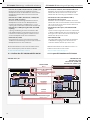 10
10
-
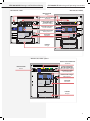 11
11
-
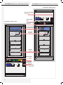 12
12
-
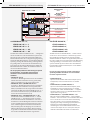 13
13
-
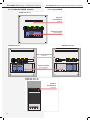 14
14
-
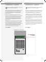 15
15
-
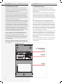 16
16
-
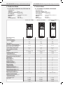 17
17
-
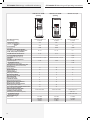 18
18
-
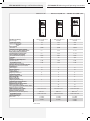 19
19
-
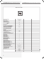 20
20
-
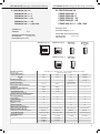 21
21
-
 22
22
-
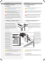 23
23
-
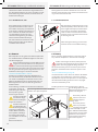 24
24
-
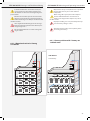 25
25
-
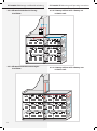 26
26
-
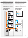 27
27
-
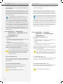 28
28
-
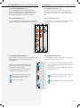 29
29
-
 30
30
-
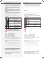 31
31
-
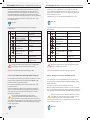 32
32
-
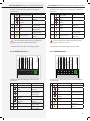 33
33
-
 34
34
-
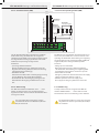 35
35
-
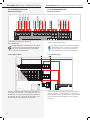 36
36
-
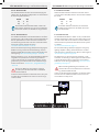 37
37
-
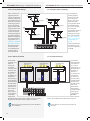 38
38
-
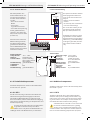 39
39
-
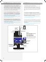 40
40
-
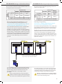 41
41
-
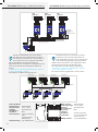 42
42
-
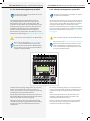 43
43
-
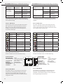 44
44
-
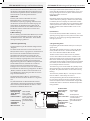 45
45
-
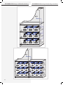 46
46
-
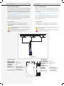 47
47
-
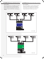 48
48
-
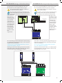 49
49
-
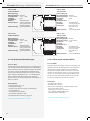 50
50
-
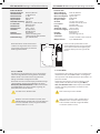 51
51
-
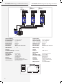 52
52
-
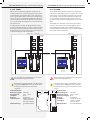 53
53
-
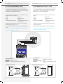 54
54
-
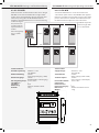 55
55
-
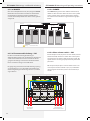 56
56
-
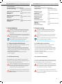 57
57
-
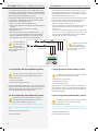 58
58
-
 59
59
-
 60
60
-
 61
61
-
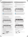 62
62
-
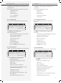 63
63
-
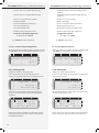 64
64
-
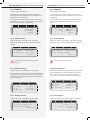 65
65
-
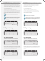 66
66
-
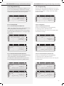 67
67
-
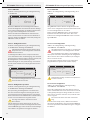 68
68
-
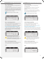 69
69
-
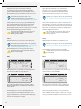 70
70
-
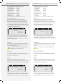 71
71
-
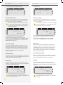 72
72
-
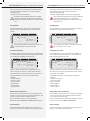 73
73
-
 74
74
-
 75
75
-
 76
76
-
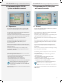 77
77
-
 78
78
-
 79
79
-
 80
80
-
 81
81
-
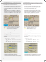 82
82
-
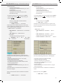 83
83
-
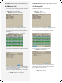 84
84
-
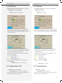 85
85
-
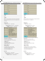 86
86
-
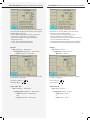 87
87
-
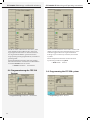 88
88
-
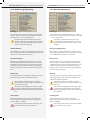 89
89
-
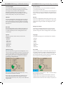 90
90
-
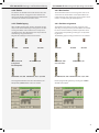 91
91
-
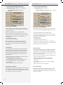 92
92
-
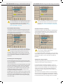 93
93
-
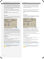 94
94
-
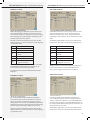 95
95
-
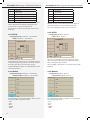 96
96
-
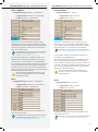 97
97
-
 98
98
-
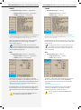 99
99
-
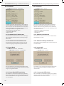 100
100
-
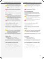 101
101
-
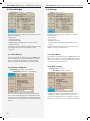 102
102
-
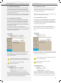 103
103
-
 104
104
-
 105
105
-
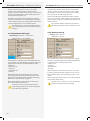 106
106
-
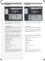 107
107
-
 108
108
-
 109
109
-
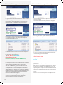 110
110
-
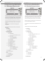 111
111
-
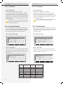 112
112
-
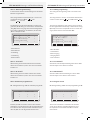 113
113
-
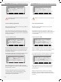 114
114
-
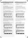 115
115
-
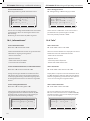 116
116
-
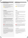 117
117
-
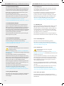 118
118
-
 119
119
-
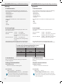 120
120
-
 121
121
-
 122
122
-
 123
123
-
 124
124
-
 125
125
-
 126
126
-
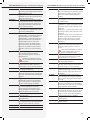 127
127
-
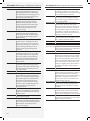 128
128
-
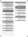 129
129
-
 130
130
-
 131
131
-
 132
132


INOTEC CPS 220/64/J-SKÜ Mounting And Operating Instructions
- Typ
- Mounting And Operating Instructions
- Dieses Handbuch ist auch geeignet für
in anderen Sprachen
- English: INOTEC CPS 220/64/J-SKÜ
Sonstige Unterlagen
-
Honeywell IB2 Mounting And Connection Instructions
-
 Nimbus Water Systems ROXXANE FLY Benutzerhandbuch
-
 Advanced Engineering MIMIC Schnellstartanleitung
-
Megger PCITS2000/2 Benutzerhandbuch
-
Casio AP-700 Bedienungsanleitung
-
-
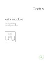 Occhio AIR Mounting instructions
-
Mastervolt Digital AC 1x6A Benutzerhandbuch
-
Motorola XT420 Benutzerhandbuch
-
Electro-Voice CPS8.5 Bedienungsanleitung


