Pepperl+Fuchs RLK39-54-Z/31/40a/116 Bedienungsanleitung
- Typ
- Bedienungsanleitung

alle Maße in mm
DimensionsAbmessungen
Technische Daten Technical data
Elektrischer Anschluss Electrical connection Adressen/Addresses
Sicherheitshinweise:
•Vor der Inbetriebnahme Betriebsanleitung lesen
• Anschluss, Montage und Einstellung nur durch Fachpersonal
• Kein Sicherheitsbauteil gemäß EU-Maschinenrichtlinie
Security Instructions:
• Read the operating instructions before attempting commissioning
• Installation, connection and adjustments should only be undertaken by specialist personnel
• Not a safety component in accordance with the EU Machinery Directive
all dimensions in mm
www.pepperl-fuchs.com
Pepperl+Fuchs GmbH
68301 Mannheim · Germany
Tel. +49 621 776-4411
Fax +49 621 776-27-4411
E-mail: fa-inf[email protected]
Worldwide Headquarters
Pepperl+Fuchs GmbH · Mannheim · Germany
E-mail: fa-inf[email protected]
USA Headquarters
Pepperl+Fuchs Inc. · Twinsburg · USA
E-mail: fa-inf[email protected]
Asia Pacific Headquarters
Pepperl+Fuchs Pte Ltd · Singapore
E-mail: fa-inf[email protected]
Company Registration No. 199003130E
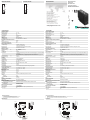
LED gelb
LED rot
optische Achse
Empfänger
optische Achse
Sender
Klemmraum
Empfindlichkeitseinsteller
Hell-/Dunkel-Umschalter
LED gelb
LED rot
nach Abnehmen des
Deckels sichtbar nur bei Version -Z:
Schalter für Timerfunktion
nur bei Version -Z:
Zeiteinsteller
45
25
19
6
64
15
17
28.4
40.5
ø 5.4 ø 5.4
75
81.8
3
4
1
2
PG9
DL
1 2 3 4
Reflexionslichtschranke
mit Klemmraum
Retroreflective sensor
with terminal compartment
RLK39-54-Z/31/40a/116
Allgemeine Daten
Betriebsreichweite 0 ... 5 m
Reflektorabstand 0,1 ... 5 m
Grenzreichweite 6 m
Referenzobjekt Reflektor H50
Lichtsender LED rot
Lichtart rot, Wechsellicht
Polarisationsfilter ja
Fremdlichtgrenze IEC / EN 60947-5-2 , 10000 Lux
Kenndaten funktionale Sicherheit
MTTFd 803 a
Gebrauchsdauer (TM) 20 a
Diagnosedeckungsgrad (DC) 0 %
Anzeigen/Bedienelemente
Funktionsanzeige LED gelb: Schaltzustand
LED rot: Vorausfallanzeige
Bedienelemente Tastweiteneinsteller, Hell-/Dunkelumschalter
Bedienelemente Schalter für Timerfunktion
Elektrische Daten
Betriebsspannung UB12 ... 240 V DC
24 ... 240 V AC (50 ... 60 Hz)
Welligkeit 10 %
Leerlaufstrom I0≤ 50 mA
Schutzklasse II, Bemessungsspannung ≤ 250 V AC bei Verschmutzungsgrad 1-2 nach IEC 60664-
1 Achtung !
Die Schutzklasse 2 ist nur gültig bei geschlossenem Klemmraum. Ausgangsstrom-
kreis mit Basisisolierung zum Steuerstromkreis nach IEC/EN 61140
Leistungsaufnahme P0≤ 3 VA
Bereitschaftsverzug tv≤ 300 ms
Ausgang
Schaltungsart hell-/dunkelschaltend
Signalausgang 1 Relaisausgang
Schaltspannung max. 240 V AC ; 150 V DC
Schaltstrom max. 3 A
Schaltleistung DC: max. 90 W AC: max: 750 VA
Schaltfrequenz f ≤ 25 Hz
Ansprechzeit ≤ 20 ms
Timerfunktion Ein-/Ausverzögerung oder Impulsverlängerung wählbar
Umgebungsbedingungen
Umgebungstemperatur -25 ... 55 °C (-13 ... 131 °F)
Lagertemperatur -40 ... 70 °C (-40 ... 158 °F)
Mechanische Daten
Gehäusebreite 25 mm
Gehäusehöhe 64 mm
Gehäusetiefe 75 mm
Schutzart IP67
Anschluss Klemmraum PG9, Aderquerschnitt ≤2,5 mm2
Material
Gehäuse PBT
Lichtaustritt PMMA
Masse ca. 110 g
Allgemeine Informationen
Lieferumfang Montagehilfe , Reflektor
Normen- und Richtlinienkonformität
Richtlinienkonformität EMV-Richtlinie 2004/108/EG
EMV-Richtlinie 2004/108/EG EN 60947-5-2:2007+A1:2012 IEC 60947-5-2:2007+A1:2012
Normenkonformität
Produktnorm EN 60947-5-2:2007
IEC 60947-5-2:2007
Zulassungen und Zertifikate
EAC-Konformität TR CU 020/2011
TR CU 004/2011
CCC-Zulassung Certified by China Compulsory Certification (CCC)
Zulassungen CE
LED yellow
LED red
Optical axis receiver
Optical axis emitter
Terminal compartment
Sensivity adjuster
Light/dark on, switchable
only for version -Z:
Timer mode switch
only for version -Z:
Time adjuster
LED yellow
LED red
Back view (with
cover removed)
45
25
19
6
64
15
17
28.4
40.5
ø 5.4 ø 5.4
75
81.8
3
4
1
2
PG9
DL
1 2 3 4
08/03/2018
Date:
~/+UB
~/0 V
NO
C
2
1
3
4
General specifications
Effective detection range 0 ... 5 m
Reflector distance 0.1 ... 5 m
Threshold detection range 6 m
Reference target H50 reflector
Light source LED red
Light type modulated visible red light
Polarization filter yes
Ambient light limit IEC / EN 60947-5-2 , 10000 Lux
Functional safety related parameters
MTTFd 803 a
Mission Time (TM) 20 a
Diagnostic Coverage (DC) 0 %
Indicators/operating means
Function indicator LED yellow: switching state
LED red: pre-fault indication
Control elements Sensing range adjuster, light-on/dark-on changeover switch
Control elements switch for timer function
Electrical specifications
Operating voltage UB12 ... 240 V DC
24 ... 240 V AC (50 ... 60 Hz)
Ripple 10 %
No-load supply current I0≤ 50 mA
Protection class II, rated voltage ≤ 250 V AC with pollution degree 1-2 according to IEC 60664-1 Cau-
tion!
The protection class 2 is only valid when the terminal compartment is closed. output
circuit has basic insulation to control circuit according to IEC/EN 61140
Power consumption P0≤ 3 VA
Time delay before availability tv≤ 300 ms
Output
Switching type light/dark on
Signal output 1 relay output
Switching voltage max. 240 V AC ; 150 V DC
Switching current max. 3 A
Switching power DC: max. 90 W AC: max. 750 VA
Switching frequency f ≤ 25 Hz
Response time ≤ 20 ms
Timer function On-/off-delay or pulse extension on choice
Ambient conditions
Ambient temperature -25 ... 55 °C (-13 ... 131 °F)
Storage temperature -40 ... 70 °C (-40 ... 158 °F)
Mechanical specifications
Housing width 25 mm
Housing height 64 mm
Housing depth 75 mm
Degree of protection IP67
Connection terminal compartment PG9, ≤2.5 mm2
Material
Housing PBT
Optical face PMMA
Mass approx. 110 g
General information
Scope of delivery Mounting aid , Reflector
Compliance with standards and direc-
tives
Directive conformity EMC Directive 2004/108/EC
EMC Directive 2004/108/EC EN 60947-5-2:2007+A1:2012 IEC 60947-5-2:2007+A1:2012
Standard conformity
Product standard EN 60947-5-2:2007
IEC 60947-5-2:2007
Approvals and certificates
EAC conformity TR CU 020/2011
TR CU 004/2011
CCC approval Certified by China Compulsory Certification (CCC)
Approvals CE
~/+UB
~/0 V
NO
C
2
1
3
4
DIN A3 -> A7
Part. 088823 45-0843J
Doc.
S

Bestimmungsgemäße Verwendung:
Eine Reflexionslichtschranke enthält Sender und Empfänger in einem Gehäuse. Das Licht des Senders
wird von einem Reflektor zum Empfänger zurückgestrahlt. Bei Unterbrechung des Lichtstrahls durch ein
Objekt wird die Schaltfunktion ausgelöst.
Montagehinweise:
Die Sensoren können über Durchgangsbohrungen direkt befestigt werden oder über den mitgelieferten
Haltewinkel.
Die Untergrundfläche muss plan sein, um Gehäuseverzug beim Festziehen zu vermeiden. Es empfiehlt
sich, die Mutter und Schraube mit Federscheiben zu sichern, um einer Dejustierung des Sensors vorzu-
beugen.
Justierung:
Montieren Sie den geeigneten Reflektor gegenüber der Lichtschranke. Nach der Grobeinstellung auf den
Reflektor wird der Sensor (ohne Objekt) durch horizontales und vertikales Schwenken so optimal auf den
Reflektor ausgerichtet, dass die gelbe Leuchtanzeige konstant leuchtet. Bei ungenauer Ausrichtung
leuchtet die rote LED.
Kontrolle Objekterfassung:
Das Objekt in den Strahlengang bringen. Wird das Objekt erfasst, erlischt die gelbe LED. Leuchtet die gel-
be LED weiterhin muss die Empfindlichkeit am Potentiometer so lange reduziert werden bis sie erlischt.
Nach Entfernen des Objektes leuchtet die Anzeige-LED gelb wieder konstant.
Bei Verschlechterung des Empfangs (Verschmutzung oder Dejustage) und ungenügender Funktionsres-
erve leuchtet die rote LED im Empfänger.
Reinigung:
Wir empfehlen in regelmäßigen Abständen den Lichtaustritt zu reinigen und Verschraubungen, sowie die
Steckverbindungen zu überprüfen.
Conventional use:
The reflex light beam switch contains the emitter and receiver in a single housing. The light from transmitter
is beamed back from a reflector to the receiver. If an object interrupts the light beam the switching function
is initiated.
Mounting instructions:
The sensor can be fastened over the through-holes directly or with the included support angle.
The base surface must be flat to avoid distorting the housing during mounting. It is advisable to secure the
bolts and screws with washers so that the sensor does not become misaligned.
Instructions for adjustment:
Connect the sensor to operating voltage, the LED yellow lights up constantly.
Mount suitable reflector opposite light beam switch and align roughly.
The exact adjustment takes by swivelling the sensor horizontally and vertically. With optimum light recep-
tion the yellow LED lights up constantly. In case of bad alignment, the red LED lights up.
Object detection check:
Move the object into the light beam. If the object is recorded, the yellow LED switch off. If it is not switch
off, reduce the sensitivity with the potentiometer until the switches off. It should light up constantly again
when the object is removed.
The red LED lights up if reception deteriorates (e.g. soiled lenses or by maladjustment) and when falling
short of the stability control.
lustration:
We recommend that you clean the optical interfaces and check the plug-in connections and screw con-
nections at regular intervals.
X
Y
H85-2
C110-2
H50
Charakteristische Ansprechkurve
Courbe de response caractéristique
Curve di risposta caratteristica
Characteristic response curve
Curva de respuesta característica
Möglicher Abstand (Versatz) zwischen
optischer Achse und Referenzobjekt.
Permissible distance (offset) between
optical axis and reference target.
Ecart possible entre l'axe optique et la
cible de référence.
Desplazamiento entre el eje óptico y
objeto de referencia.
Distanza possibile (sfalsato) tra l'asse
ottico e l'ogetto di riferimento.
0
20
40
60
80
100
120
140
160
180
200
0246810121416
Y [mm]
X [m]
Funktionsreserve, Stability control, Réserve de fonctionnement,
Reserva de función, Funzione riserva
X [mm]
X
100
10
1
0.1
0 2 4 6 8 10 12 14 16
Relative Empfangslichtstärke
Intensité relative de la lumière reçue
Intensità relativa luce in ricezione
Relative received light strength
Potencia relativa de recepción lumínica
Beschreibung/Desciption
-
 1
1
-
 2
2


Pepperl+Fuchs RLK39-54-Z/31/40a/116 Bedienungsanleitung
- Typ
- Bedienungsanleitung
in anderen Sprachen
Verwandte Artikel
-
Pepperl+Fuchs RLK39-54-5594/31/40a/116 Bedienungsanleitung
-
-
-
-
-
-
-
-
-