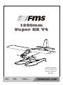
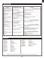
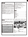
FMS 1220mm Super EZ V4 Bedienungsanleitung
- Kategorie
- Ferngesteuertes Spielzeug
- Typ
- Bedienungsanleitung

1220mm
Super EZ V4
FLOAT RIGID
Float included Durable EPO
STABLE
Smooth flying performance
FMSMODEL.COM
Manuel d’utilisation
Instruction manual
Bedienungsanleitung
操作手册

WARNING: Read the ENTIRE instruction manual to become familiar with the features of the product before operating.
Failure to operate the product correctly can result in damage to the product,personal property and cause serious injury.
This is a sophisticated hobby product and NOT a toy. It must be operated with caution and common sense and failure to do so
could result in injury or damage to the product or other property. This product is not intended for use by children without direct
adult supervision.
This manual contains instructions for safety operation and maintenance. It is essential to read and follow all the instructions and
warnings in the manual prior to assembly, setup or use, in order to operate and avoid damage or serious injury.
WARNING
As the user of this product, you are solely responsible for operating in a manner that does not endanger yourself and others or
result in damage to the product or the property of others. This model is controlled by a radio signal subject to interference from
many sources outside your control. This interference can cause momentary loss of control so it is advisable to always keep a
safe distance in all directions around your model, as this margin will help avoid collisions or injury.
Age Recommendation: Not for children under 14 years. This is not a toy.
·Never operate your model with low transmitter batteries.
·Always operate your model in an open area away from cars, traffic or people.
·Avoid operating your model in the street where injury or damage can occur.
·Never operate the model in populated areas for any reason.
·Carefully follow the directions and warnings for this and any optional support equipment you use (chargers,rechargeable
battery packs, etc.)
·Keep all chemicals, small parts and anything electrical out of the reach of children.
·Moisture causes damage to electronics. Avoid water exposure to all equipment not specifically designed and protected for this
purpose.
·Never lick or any place of any your model in your mouth as it could cause serious injury or even death.
Lithium Polymer (Li-Po) Battery Warning
CAUTION: Always follow the manufacturer’s instructions for safe use and disposal of batteries. Fire, property
damage, or serious injury can result from the mishandling of Li-Po batteries.
By handling, charging or using a Li-Po Battery you assume all risks associated with lithium batteries.
If at any time the batteries begin to swell or balloon, discontinue use immediately!
Always store the batteries at room temperature in a dry area to extend the life of the battery. Always transport
or temporarily store the battery in a temperature range of 40-120F. Do not store the battery or model in a car or in direct sunlight.
If stored in a hot car, the battery can be damaged or even catch fire.
Never use a Ni-Mh Charger to charge Li-Po Batteries. Failure to charge the battery with a Li-Po compatible charger
may cause fire resulting in personal injury and property damage.
Never discharge Li-Po Cells below 3V.
Never leave charging batteries unattended.
Never charge damaged batteries.
Charging the Flight Battery Warning
Use a battery charger that is designed to safely charge the Li-Po Battery. Read the charger instructions care
fully before use. When charging the battery, make certain the battery is on a heat resistant surface. It is also highly
recommended to place the Li-Po Battery inside a fire resistant charging bag readily available at hobby shops or
online.
p w

3
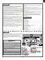
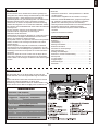
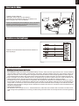
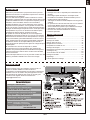
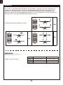
Before assembly, please inspect the contents of the kit. The
photo below details the contents of the kit with labels. If any
parts are missing or defective, please identify the name or
part number (refer to the spare parts list near the end of the
manual) then contact your local shop or email us: support
Kit contents
Introduction
Kit contents
Model assembly
Battery installation
Receiver diagram
Preflight check
Clevis installation
Control horn and servo arm settings
Center of gravity(CG)
Before flying the model
Flying course
Troubleshooting
Spare parts list content
Table of contents
·····························································
·····
3
·························································3
·······················································4
············································· ········ 7
·········································
··
········ 7
··································
·····
·····
·····
·····
7
······················································9
··························
·················
9
···············································
9
··············································10
···························································10
······················································11
············································11
Introduction
Wingspan: 1220mm(48.0in)
Overall length: 1020mm(40.2in)
Flying weight: ~ 920g(32.5oz)1120(39.05oz)
Motor size: 3136-KV1200
Wing load: 31.34 g/dm² (0.07oz/in²)
Wing area: 28.4 dm² (440.2sq.in)
ESC: 20A
Servo: No Float 9g Servo x 4, Float Included Servo
x 5
Recommended battery: 11.1V 1300-2200mAh 25C
Specifications
@fmsmodel.com
• High strength, lightweight metal landing gear suitable for any
ground surface
• 3S 1300mAh Lipo pack provides 10-15 minute flight times
(Battery included with the RTF set)
• Precision water-proof servos for all-weather operations
• Single-piece horizontal stabilizer for added precision
• New and improved spinner reduces vibration significantly
• Optional floats
A.
D.
E.
F. G.
J.
H.
I.
M.
N.
O.
L.
K.
B.
C.
FMS has always dedicated its engineering efforts towards making
aircraft suitable for every skill level. The SuperEZ has always
been a perfect beginner-friendly sport aircraft.
Using a large, high-winged design constructed out of lightweight
EPO foam, the SuperEZ has an ultra-low wing loading and stable
flight characteristics- giving beginner pilots great handling even at
slow speeds. An improved brushless power system and propeller
gives the aircraft ample power while still maintaining 10-15 minute
flight times. A high strength, lightweight metal landing gear set
absorbs even the hardest landings.
For easy transportation, the SuperEZ is designed with a
quick-release mechanism that can release the wing in a matter of
seconds.
Building on the success of the SuperEZ V2, the V3 features an
improved one-piece horizontal stabilizer and a nose-cone that
significantly reduces vibrations.
Built upon the successful Super EZ V3, FMS has completely
upgraded the digital 9g servos to ensure pinpoint precision and
bulletproof reliability. The addition of attractive purple accents to
the color scheme make the Super EZ V4 a head-turner at every
field!
Like the SuperEZ V2 and V3, the V4 can be installed with floats!
Allowing for water and snow operations
As one of FMS’ mainline products, the SuperEZ V4 utilizes the
latest in FMS’ design language. It will grow with the pilot as they
progress into more sophisticated flight maneuvers.
Features:
• Glue-less construction, the SuperEZ can be assembled in 5
minutes
• Quick-release main wing for easy transportation
• Paedator brushless power system for greater power-to-weight
ratio

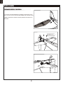
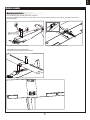
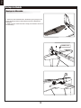
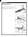
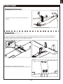
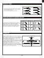
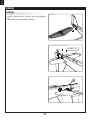
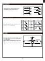
Horizontal stabilizer installation
4
Model assembly
1. Insert the horizontal stabilizer into fuselage in the direction of the
arrow as shown. Secure the horizontal stabilizer with included screws.
2.With the elevator servo centered, connect the pushrod to the control horn on
the elevator.
HKM3.0*32

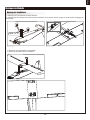
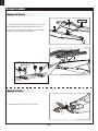
Main wing installation
1.Fix the landing gear set with the screw, as shown.
2.Find the Y-harness and connect it to both aileron servos.Connect the Y-harness to the receiver, then place the receiver
into the fuselage.
5
Model assembly
HKM 3.0*10
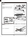
3. Assemble the main wing as shown.
4.Secure the main wing with bolts as shown.

6
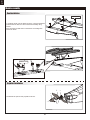
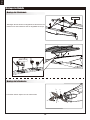
1. Install the struts onto the floats as shown- using the hardware
provided with the float set. Secure the float assembly using
screws.
2.Fix the floats set with struts on the bottom of fuselage with
screws as shown.
1.Assemble the spinner and propeller as shown.
Model assembly
Propeller installation
Float installation
Screws 3*4
HKM 3.0*10

Important ESC and model information
The ESC included with the model has a safe start. If the motor battery is connected to the ESC and the throttle stick is not in
the low throttle or off position, the motor will not start until the throttle stick is moved to the low throttle or off position. Once the
throttle stick is moved to the low throttle or off position, the motor will emit a series of beeps. Several beeps with the same tune
means the ESC has detected the cells of the battery. The count of the beeps equals the cells of the battery. The motor is now
armed and will start when the throttle is moved.
The motor and ESC come pre-connected and the motor rotation should be correct. If for any reason the motor is rotating in the
wrong direction, simply reverse two of the three motor wires to change the direction of rotation.
The motor has an optional brake setting. The ESC comes with brake switched off and we recommend that the model be flown
with the brake off. However, the brake could be accidentally switched on if the motor battery is connected to the ESC while the
throttle stick is set at full throttle. To switch the brake off, move the throttle stick to full throttle and plug in the motor battery. The
motor will beep one time. Move the throttle stick to low throttle or the off position. The motor is ready to run and the brake will
be switched off.
Battery Selection and Installation. We recommend the 11.1V 1300-2200mAh 25C Li-Po battery. If using another battery, the
battery must be at least a 11.1V 1300-2200mAh 25C battery. Your battery should be approximately the same capacity, dimen-
sion and weight as the 11.1V 1300-2200mAh 25C Li-Po battery to fit the fuselage without changing the center of gravity signifi-
cantly.
1.
2.
3.
4.
1. Apply the hook tape to the cable end of the battery.
2. Slide the battery into the battery hatch with the power supply cable toward
the rear end of the plane and the hook tape facing the bottom of the battery
hatch.
Note: You may need to relocate the battery position to acheieve the correct
CG for your model.
7
Battery installation
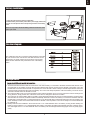
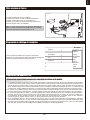
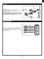
Receiver diagram
Preflight check
The cables from the servo connector board should be connected
to your receiver in the order shown. Note that the LEDs can be
powered by any spare channel on the receiver. Tuck the wire
leads into the recessed cavity towards the rear of the battery
hatch.

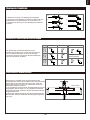
Transmitter and model setup
Before getting started, bind your receiver with your transmitter.
Please refer to your transmitter manual for proper operation.
CAUTION: To prevent personal injury, DO NOT install the propel-
ler assembly onto the motor shaft while testing the control surfac-
es. DO NOT arm the ESC and do not turn on the transmitter until
the Transmitter Manual instructs you to do so.
Tips: Make sure all control sticks on your radio are in the neutral
position (rudder, elevator, ailerons) and the throttle is in the OFF
position. Make sure both ailerons move up and down (travel) the
same amount. This model tracks well when the left and right
ailerons travel the same amount in response to the control stick.
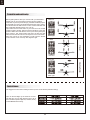
Move the controls on the transmitter to make sure the aircraft
control surface moves correctly. See diagrams right.
8
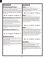
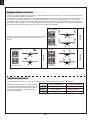
Control throws
The suggested control throw setting for the Super EZ are as follows (dual rate setting):
Tips: On the first flight, fly the model in low rate.
The first time you use high rates,be sure to fly at
low to medium speeds. High rate, as listed, is only
for EXTREME maneuvering.
Aileron
Bank left
Bank right
Elevator
Climb
Descend
Steering Rudder
Steer left
Steer right
15 10
10
8
15
12

9
a.
b.
c.
d.
e.
f.
Clevis installation
1.Pull the tube from the clevis to the linkage.
2.Carefully spread the clevis, then insert the clevis pin into the
desired hole in the control horn.
3.Move the tube to hold the clevis on the control horn.
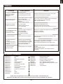
Control horn and servo arm settings
The table shows the factory settings for the control horns
and servo arms. Fly the aircraft at the factory settings
before making changes.
After flying,you may choose to adjust the linkage positions
for the desired control response.
Check the C.G. (Center of gravity)
When balancing your model, adjust the battery as necessary
so the model is level or slightly nose down. This is the correct
balance point for your model. After the first flights, the CG
position can be adjusted for your personal preference.
1. The recommended Center of Gravity (CG) location for your
model is(55-60mm) from the leading edge of the main wing
(as shown) with the battery pack installed. Mark the location of
the CG on top of the wing.
2. When balancing your model, support the plane at the marks
made on the bottom of the main wing with your fingers or a
commercially available balancing stand. This is the correct
balance point for your model. Make surethe model is assembled
and ready for flight before balancing.
55mm-60mm
More control throw
Less control throw
Horns Arms
ElevatorRudderAilerons

Take off
Maintenance
Landing
Find a suitable flying site
Perform the range check for your plane
Monitor your flight time
Find a flying site clear of buildings, trees, power lines and
other obstructions. Until you know how much area will be
required and have mastered flying your plane in confined
spaces, choose a site which is at least the size of two to three
football fields - a flying field specifically for R/C planes is best.
Never fly near people - especially children, who can wander
unpredictably.
As a precaution, an operational ground range test should be
performed before the first flight each time you go out.
Performing a range test is a good way to detect problems
that could cause loss of control such as low batteries, defective
or damaged radio components, or radio interference. This
usually requires an assistant and should be done at the actual
flying site you will be using.
First turn on the transmitter, then install a fully-charged battery
into the fuselage. Connect the battery and install the hatch.
Remember, use care not to bump the throttle stick. Otherwise,
the propeller/fan will turn and possibly cause damage or injury.
Note: Please refer to your Transmitter Manual that came with
your radio control system to perform a ground range check. If
the controls are not working correctly or if anything seems
wrong, do not fly the model until you correct the problem. Make
certain all the servo wires are securely connected to the
receiver and the transmitter batteries have a good connection.
Monitor and limit your flight time using a timer (such as on a
wristwatch or in your transmitter if available). When the
batteries are getting low you will usually notice a performance
drop before the ESC cuts off motor power, so when the plane
starts flying slower you should land. Often (but not always)
power can be briefly restored after the motor cuts off by
holding the throttle stick all the way down for a few seconds.
To avoid an unexpected dead-stick landing on your first flight,
set your timer to a conservative 4 minutes. When your alarm
sounds you should land right away.
10
Before flying the model
Flying course
While applying power, slowly steer to keep the model straight.
The model should accelerate quickly. As the model gains flight
speed you will want to climb at a steady and even rate. It will
climb out at a nice angle of attack (AOA).
Flying
Always choose a wide-open space for flying your plane. It is
ideal for you to fly at a sanctioned flying field. If you are not
flying at an approved site always avoid flying near houses,
trees, wires and buildings. You should also be careful to avoid
flying in areas where there are many people, such as busy
parks, schoolyards, or soccer fields. Consult laws and
ordinances before choosing a location to fly your aircraft. After
takeoff, gain some altitude. Climb to a safe height before trying
technical manoeuvres, including high speed passes, inverted
flight, loops, and point rolls.
Land the model when you hear the motor pulsing (LVC) or if
you notice a reduction in power. If using a transmitter with a
timer, set the timer so you have enough flight time to make
several landing approaches.
The model’s three point landing gear allows the model to land
on hard surfaces. Align model directly into the wind and fly
down to the ground. Fly the airplane down to the ground using
1/4-1/3 throttle to keep enough energy for proper flare. Before
the model touches down, always fully decrease the throttle to
avoid damaging the propeller or other components. The key to
a great landing is to manage the power and elevator all the
way to the ground and set down lightly on the main landing
gear. After a few flights you will find the model can be set down
lightlyon the mains and you can hold the nose wheel off
balancing themodel on the mains until it slows and gently
settles the nose.
Repairs to the foam should be made with foam safe adhesives
such as hot glue, foam safe CA, and 5min epoxy. When parts
are not repairable, see the Spare Parts List for ordering by item
number.
Always check to make sure all screws on the aircraft are
tightened. Pay special attention to make sure the spinner is
firmly in place before every flight.

11
Trouble shooting
Problem Possible Cause Solution
Aircraft will not respond to
the throttlebut responds to
other controls.
-ESC is not armed.
-Throttle channel is reversed.
-Lower throttle stick and throttle trim to lowest settings.
-Reverse throttle channel on transmitter.
Extra propeller noise or
extra vibration.
-Damaged spinner, propeller,
motor or motor mount.
-Loose propeller and spinner parts.
-Propellor installed backwards.
-Replace damaged parts.
-Tighten parts for propeller adapter, propeller and spinner.
-Remove and install propeller correctly.
Reduced flight time or
aircraft underpowered.
-Flight battery charge is low.
-propeller installed backward.
-Flight battery damaged.
-Completely recharge flight battery.
-Replace flight battery and follow flight battery
instructions.
Control surface does not
move, or is slow to respond
to control inputs.
-Control surface, control horn,
linkage or servo damage.
-Wire damaged or connections
loose.
-Replace or repair damaged parts and adjust controls.
-Do a check of connections for loose wiring.
Controls reversed.
Channels are reversed in the
transmitter.
Do the control direction test and adjust controls for
aircraft and transmitter.
-Motor loses power
-Motor power pulses then
motor loses power.
-Damage to motor, or battery.
-Loss of power to aircraft.
-ESC uses default soft Low Voltage
Cutoff(LVC).
-Do a check of batteries, transmitter, receiver, ESC, motor
and wiring for damage(replace as needed).
-Land aircraft immediately and recharge flight battery.
LED on receiver flashes
slowly.
Power loss to receiver.
-Check connection from ESC to receiver.
-Check servos for damage.
-Check linkages for binding.
Spare parts list content
FMSPH101-3
FMSPH102-1
FMSPH103-2
FMSPH104-1
FMSPH105-1
FMSPH106-1
FMSPH108-1
FMSPH109
FMSPH110-1
FMSPH114-1
FMSPH115-1
FMSPH116-1
FMSPROP022
FMSDJ009
Fuselage
Main wing
Horizontal stabilizer
Cowl
Battery cover
Spinner
Front landing gear set
Tire set
Wing bolt plate
Sticker
Linkage rods
Screws
Propeller
Motor mount
FMSBM011
FMSDZ018
FMSKV1200
PRESC004-1
FMS9GDP
FMS9GDPW
FMSCHR01
FMSFLT004
Motor board
Motor shaft
3136-KV1200 motor
20A ESC
9g digital gear servo positive
9g digital gear servo positive
with waterproof function)
Charger
Float set
Visit our website: www.fmsmodel.com to see photo of this product. Enter the key word "ESC" in the search bar for the
stock ESC instruction manual.

12
WARNUNG: Lesen Sie die GESAMTE Bedienungsanleitung, um sich vor der Inbetriebnahme mit den Funktionen
des Produkts vertraut zu machen.
Wenn das Produkt nicht ordnungsgemäß bedient wird, kann dies zu Schäden am Produkt oder persönlichem
Eigentum führen und schwere Verletzungen verursachen.
Dieses Produkt ist kein Spielzeug! Es muss mit Vorsicht und gesundem Menschenverstand betrieben werden.
Andernfalls kann es zu Verletzungen oder Schäden am Produkt oder anderen Sachwerten führen. Dieses Produkt
ist nicht für den Betrieb durch Kinder ohne direkte Aufsicht von Erwachsenen vorgesehen.
Diese Anleitung enthält Hinweise zu Sicherheit und Wartung. Es ist wichtig, dass vor der Verwendung alle
Anweisungen und Warnungen in der Anleitung gelesen und befolgt werden, um Schäden oder schwere
Verletzungen zu vermeiden.
Warnhinweise
Als Benutzer dieses Produkts sind Sie allein dafür verantwortlich dieses Produkt so zu betreiben, dass weder Sie
selbst noch andere gefährdet oder Schäden am Produkt oder Eigentum anderer verursacht werden.
Dieses Modell wird von einem Funksignal gesteuert, das von vielen Quellen außerhalb Ihrer Kontrolle gestört
werden kann. Solche Störungen können zu einem vorübergehenden Kontrollverlust führen. Daher sollte immer
einen Sicherheitsabstand zu Personen und Gebäuden eingehalten werden.
Altersempfehlung: Nicht für Kinder unter 14 Jahren. Dies ist kein Spielzeug.
· Betreiben Sie Ihr Modell niemals mit leeren Senderbatterien.
· Betreiben Sie Ihr Modell immer in einem offenen Bereich, abseits von Gebäuden, Verkehr oder Personen.
· Befolgen Sie die gesetzlichen Regelungen Ihres Landes zum Betrieb von ferngesteuerten Modellflugzeugen.
· Befolgen Sie sorgfältig die Anweisungen und Warnungen für dieses und alle unterstützenden Geräte, die Sie
verwenden (Ladegeräte, wiederaufladbare Akkus usw.).
· Bewahren Sie alle Chemikalien, Kleinteile und elektrischen Geräte außerhalb der Reichweite von Kindern auf.
· Feuchtigkeit verursacht Schäden an der Elektronik. Vermeiden Sie, dass die Produkte Wasser ausgesetzt
werden, die nicht speziell für diesen Zweck entworfen und geschützt sind.
· Nehmen Sie Teile des Produkts niemals in den Mund, da dies zu schweren Verletzungen oder sogar zum Tod
führen kann.
VORSICHT: Befolgen Sie immer die Anweisungen des Herstellers zur sicheren Verwendung und Entsorgung
von Batterien. Durch falsche Handhabung von Li-Po-Batterien können Feuer, Sachschäden oder schwere
Verletzungen verursacht werden.
Seien Sie sich über alle Risiken klar, die mit dem Umgang von Lithium Polymer (LiPo) Akkus verbunden sind.
Wenn die Akkus zu irgendeinem Zeitpunkt anschwellen oder aufblähen, verwenden Sie diese auf keinen Fall
mehr!
Um die Lebensdauer des Akkus zu verlängern sollten dieser bei Zimmertemperatur in einem trockenen Bereich
gelagert werden. Bewahren Sie den Akku oder das Modell nicht in einem Auto oder in direktem Sonnenlicht
auf. Wenn der Akku über einen längeren Zeitraum zu hohen Temperaturen ausgesetzt wird kann dieser
beschädigt werden oder sogar Feuer fangen.
Verwenden Sie niemals ein NiMh-Ladegerät, um Li-Po-Akkus aufzuladen. Wenn der Akku nicht mit einem
Li-Po-kompatiblen Ladegerät geladen wird, kann dies zu einem Brand führen, der zu Personen- und Sachschäden
führen kann.
Niemals Li-Po Zellen unter 3V entladen.
Lassen Sie Akkus beim Laden niemals unbeaufsichtigt.
Laden Sie niemals beschädigte Akkus auf.
Aufladen des LiPo-Akkus: Verwenden Sie ein Ladegerät, das die Li-Po-Batterie sicher aufladen kann. Lesen
Sie vor dem Gebrauch die Anweisungen des Ladegeräts sorgfältig durch. Achten Sie beim Laden des Akkus
darauf, dass sich der Akku auf einer hitzebeständigen Oberfläche befindet. Es wird auch dringend empfohlen,
den Li-Po Akku in einem feuerbeständigen LiPo-Koffer zu laden. LiPo Koffer finden Sie bei Ihrem Fachhändler
oder im Internet.
Sicherheitsvorkehrungen
Hinweise zu LiPo-Akkus

13
Bitte überprüfen Sie vor der Endmontage ob alle Teile des
Modells enthalten sind. Das folgende Bild zeigt den Inhalt des
Kits.
Sollten Teile fehlen notieren Sie sich bitte den Namen und die
Teilenummer (siehe Ersatzteilliste am Ende dieser
Bauanleitung) und kontaktieren Sie Ihren lokalen Händler oder
senden Sie uns eine E-Mail an [email protected].
Lieferumfang
Inhaltsverzeichnis
Einleitung
Spannweite: 1220 mm(48.0in)
Gesamtlänge: 1020 mm(40.2in)
Fluggewicht: ~ 920g(32.5oz)1120(39.05oz)
Motor: 3136-KV1200
Flächenbelastung: 31.34 g/dm² (0.07oz/in²)
Flächeninhalt: 28.4 dm² (440.2sq.in)
Regler: 20A
Servo: No Float 9g Servo x 4, Float Included Servo
x 5
Empfohlener Akku: 11.1V 1300-2200mAh 25C
Technische Daten
Der Hochdecker ist aus leichtem EPO-Schaum gefertigt und
verfügt über eine extrem niedrige Flächenbelastung und stabile
Flugeigenschaften - damit Anfänger auch bei niedrigen
Geschwindigkeiten ein gutes Handling haben. Ein verbessertes
Brushless Antriebssystem und ein verbesserter Propeller
verleihen der V3 Version der SuperEZ ausreichend Leistung,
während die Flugzeiten von 10-15 Minuten beibehalten werden.
Ein robustes, leichtes Metallfahrwerk nimmt selbst die härtesten
Landungen auf.
Für den einfachen Transport ist der SuperEZ mit einem
Schnellverschluss ausgestattet, der den Flügel in
Sekundenschnelle lösen kann.
Aufbauend auf dem Erfolg der SuperEZ V2, verfügt die V3 über
ein verbessertes einteiliges Höhenleitwerk und einen neuen
Spinner, der Vibrationen deutlich reduziert.
Die SuperEZ V3 kann mit optionalen Schwimmern ausgestattet
warden, die Starts und Landungen auf Wasser und Schnee
möglich Machen.
Auf der erfolgreichen Super EZ V3 aufbauend, hat FMS die
neue Super EZ V4 mit 9g Digital Servos aufgerüstet, um noch
mehr Präzision und Zuverlässigkeit zu gewährleisten. Das neue
Farbdesign macht die neue Super EZ V4 zu einem absoluten
Hingucker!
Wie bei der Super EZ V2 und V3 wird auch die Super EZ V4
neben dem Fahrwerk mit einem Schwimmer-Set ausgeliefert,
welches Starts und Landungen auf Wasser und Schnee möglich
machen.
Merkmale:
• Kleberlose Konstruktion - die SuperEZ kann in 5 Minuten
montiert werden
• Quick-Release Tragfläche für den einfachen Transport
• Robustes, leichtes Metallfahrwerk, geeignet für jede Piste
• 3S 1300mAh Lipo-Akku bietet 10-15 Minuten Flugzeiten
(Batterie im Lieferumfang des RTF-Set enthalten)
Einleitung
Lieferumfang
Montage des Modells
Einsetzen des Akkus
Anschluss an den Empfänger
Flugvorbereitungen
Montage der Gabelköpfe
Ruderhorn- und Servoarmeinstellung
Schwerpunkt
Vor dem Erstflug
Fluggrundlagen
Problemlösungen
Ersatzteile
···························································13
·······················································
···
13
················································
14
··········································
······17
····································17
·································· ···· ····
···········
·····
17
···············
·················
················
·················
··
··
··
19
19
·······································
19
·············································20
······················································20
····································
········
······
······
········
········
········
········ ········
········21
········································· ········21
A.
D.
E.
F. G.
J.
H.
I.
M.
N.
O.
L.
K.
B.
C.
• Wassergeschützte Präzisionsservos für den Allwetterbetrieb
• Einteiliges Höhenruder für zusätzliche Präzision
• Neuer und verbesserter Spinner reduziert Vibrationen
erheblich
• Optionale Schwimmer erhältlich

Montage des Höhenruder
14
Montage des Modells
1. Setzen Sie das Höhenleitwerk in Pfeilrichtung wie gezeigt in den
Rumpf. Befestigen Sie das Höhenleitwerk mit den mitgelieferten
Schrauben.
2. Stellen Sie den Höhenruder-Servo mittig und verbinden Sie es mit
der Anlenkung.
HKM3.0*32

1. Befestigen Sie das Fahrwerk mit den Schrauben.
2. Schließen Sie das Y-Kabel an den Querruder-Servosteckern an und stecken Sie das Y-Kabel in den Querruder-Ausgang Ihres
Empfängers.
15
Montage des Modells
Montage der Tragflächen
HKM 3.0*10
3. Befestigen Sie die Tragfläche wie abgebildet.
4. Sichern Sie die Fläche mit den Schrauben.

16
1. Befestigen Sie die Streben wie abgebildet am Schwimmer-Set.
2. Montieren Sie das Schwimmer-Set wie abgebildet am Rumpf.
1. Montieren Sie den Spinner und die Luftschraube.
Montage des Modells
Montage des Schwimmers
Montage der Luftschraube
Screws 3*4
HKM 3.0*10

Wichtige Informationen zum Regler
Der eingebaute Regler ist mit einer Sicherheitsschaltung versehen. Sollte der Akku angeschlossen sein und der Gashebel
nicht auf niedrig / Motor aus stehen, wird der Motor nicht starten. Wird der Gashebel ganz nach unten bewegt erzeugt der
Regler eine Tonserie. Töne in der gleichen Höhe geben die Anzahl der Zellen an die der Regler gezählt hat. Diese ist gleich
mit der Zellenanzahl des Akkus. Der Regler ist jetzt scharf geschaltet und startet den Motor wenn der Gashebel bewegt wird.
Motor und Regler sind bereits verkabelt und auch die Drehrichtung des Motors sollte korrekt sein. Sollte der Motor in die
falsche Richtung drehen, tauschen Sie zwei der drei Motoranschlusskabel um die Richtung wieder zu ändern.
Der Regler ist mit einer optionalen Bremse ausgestattet. Wir empfehlen das Modell mit der deaktivierten Bremse zu fliegen.
Es ist möglich die Bremse versehentlich zu aktivieren wenn der Akku mit dem Regler verbunden wird und der Gashebel auf
Vollgas steht. Um die Bremse wieder auszuschalten gehen Sie mit dem Gashebel wieder auf Vollgas und verbinden den Akku.
Vom Motor ertönt ein Piepton. Bewegen Sie den Gashebel auf Leerlauf oder Motor aus. Der Motor ist dann betriebsbereit und
die Bremse ausgeschaltet.
Akkuauswahl und Einbau:
Wir empfehlen einen Lipo Akku mit 11.1V 1300-2200mAh 25C. Sollten Sie einen anderen Akku verwenden muß dieser mind-
estens die gleichen Spezifikationen in Leistung und Abmessung aufweisen.damit der Schwerpunkt nicht wesentlich geändert
wird.
1.
2.
3.
4.
17
1. Nehmen Sie die Haube ab.
2. Befestigen Sie den Akku mit dem Klettband
3. Schieben Sie den geladenen Akku mit den Kabeln nach
hinten in bis ganz nach vorne im Akkufach.
Hinweis: Der Schwerpunkt des Modells kann durch verschieben
des Akkus verändert werden. Der korrekte Schwerpunkt hat
Auswirkungen auf die Flugperformance.
Einsetzen des Akkus
Anschluss an den Empfänger
Verbinden Sie die Servokabel entsprechend der Tabelle mit
Ihrem Empfänger.
Flugvorbereitungen

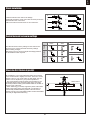
Testen der Steuerfunktionen
Bevor Sie mit diesem Schritt beginnen, binden Sie bitte der
Anleitung ihres Senders entsprechend den
Empfänger mit dem Sender.
ACHTUNG: Um mögliche Verletzungen zu vermeiden darf der
Propeller bei dem Testen der Ruder NICHT
auf der Welle montiert sein. Armieren Sie den Regler NICHT
und schalten auch nicht den Sender ein bevor
es in der Anleitung des Senders vorgeben wird.
TIPP: Stellen Sie sicher, dass alle Steuerhebel auf dem Sender
auf der neutralen Position sind und der
Gashebel auf Motor aus.
Stellen Sie sicher, dass beide Querruder den gleichen Weg im
Verhältnis zum Steuerknüppelausschlag
ausschlagen.
Bewegen Sie die Steuerhebel des Sender um sicher zu stellen,
dass sich die Ruder korrekt bewegen.
Sehen Sie dazu die Abbildungen unten. Sollten die Ruder in die
falsche Richtung arbeiten reversieren Sie
die Funktion. Lesen Sie dazu bitte in der Anleitung des Sender
nach.
18
Ruderausschläge
Die empfohlenen Ruderausschlag-Einstellungen sind (Dual Rate):
Querruder
Rollen links
Rollen rechts
Höhenruder
Steigen
Sinken
Seitenruder
Gieren links
Gieren rechts
maximale Ausschläge normale Ausschläge
Höhenruder
Querruder
Seitenruder
15mm oben / unten 10mm oben / unten
10mm oben / unten
8mm links / rechts
15mm oben / unten
12mm links / rechts
Tipp: Fliegen Sie das Modell beim ersten Flug
mit "normalen Ausschlägen". Wenn Sie zum
ersten Mal "maximale Ausschläge" verwenden,
sollten Sie bei niedrigen bis mittleren
Geschwindigkeiten fliegen.

19
a.
b.
c.
d.
e.
f.
Montage der Gabelköpfe
1. Ziehen Sie den Ring vom Gabelkopf zum Gestänge.
2. Spreizen Sie den Gabelkopf vorsichtig und führen Sie den
Gabelkopfstift in das gewünschte Loch im Ruderhorn ein.
3. Befestigen Sie den Ring um den Gabelkopf am Ruderhorn
zu halten.
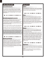
Ruderhorn- und Servoarm-Einstellungen
Die Tabelle zeigt die Werkseinstellungen für die
Ruderhörner und Servoarme. Fliegen Sie das Flugzeug
mit den Werkseinstellungen, bevor Sie Änderungen
vornehmen.Nach dem Flug können Sie die Einstellungen
nach Ihren Wünschen anpassen.
Einstellen des Schwerpunkts
Setzen Sie zum Ausbalancieren des Schwerpunktes den
Antriebsakku ein. Richten Sie den Akku so aus, dass das Modell
gerade oder mit der Nase leicht nach unten zeigt. Nach den
ersten Flügen können Sie dann den Schwerpunkt nach ihren
persönliche Vorlieben einrichten.
1. Der empfohlene Schwerpunkt für das Modell befindet sich mit
eingesetztem Akku 55-60mm von der Tragflächenvorderkante
nach hinten gemessen. Markieren Sie den Schwerpunkt auf der
Tragflächenoberseite.
2. Balancieren Sie das Modell auf einer Schwerpunktwaage aus.
Bitte beachten Sie dass das Modell dabei flugfertig ausgerüstet
sein muss.
55mm-60mm
Mehr Ruderausschlag
Weniger
Ruderausschlag
Ruderhorn Servoarm
Höhen-
ruder
Seiten-
ruder
Quer-
ruder

Starten
Instandhaltung
Landen
Finden Sie einen geeigneten Flugplatz
Führen Sie einen Reichweitentest für Ihr Modell durch
Überwachen Sie Ihre Flugzeit
Finden Sie einen Flugplatz frei von Gebäuden, Bäumen,
Stromleitungen und anderen Hindernissen. Bis Sie wissen,
wie viel Fläche Sie zum fliegen brauchen, wählen
Sie einen Platz der mindestens die Größe von 2 bis 3 Fussball-
feldern hat. Wählen Sie am besten einen RC Flugplatz eines
Modellflugvereins. Fliegen Sie dabei niemals in der Nähe von
Menschen - besonders von Kindern, die unvorhersehbar
handeln könnten.
Überwachen oder Begrenzen Sie Ihre Flugzeit mit einem Timer
(z.B. auf einer Armbanduhr, einem Smartphone oder auf Ihrem
Sender, falls verfügbar).
Wenn der Akku während des Fluges fast leer ist bemerken Sie
normalerweise einen Leistungsabfall, bevor der Regler die
Motorleistung unterbricht. Wenn das Modell langsamer wird
sollten Sie also landen.
Stellen Sie Ihren Timer auf 4 Minuten ein um einen unerwartete
Leistungsabfall zu vermeiden. Wenn der Alarm des Timers
ertönt sollten Sie landen.
20
Vor dem Erstflug
Fluggrundlagen
Beschleunigen Sie das Modell vorsichtig und steuern Sie es
langsam um es gerade zu halten. Erhöhen Sie die
Beschleunigung und halten Sie eine gleichmäßige
Geschwindigkeit um das Modell in einem schönen Anstellwinkel
in die Luft steigen zu lassen.
Fliegen
Wählen Sie immer einen weiten und offenen Platz um das
Modell zu fliegen. Besuchen Sie einen RC Flugplatz eines
Modellflugvereins. Fliegen Sie auf keinen Fall an Orten, an
denen der Betrieb eines ferngesteuerten Flugzeugs nicht
zulässig ist (Flughäfen, Naturschutzgebiete, Siedlungen, ...).
Nach dem Start bringen Sie Ihr Modell auf eine sichere
Flughöhe, bevor Sie Flugmanöver wie Rollen,Loopings oder
ähnliches ausprobieren.
Landen Sie das Modell, sobald Sie eine Leistungsreduzierung
bemerken oder Ihr eingestellter Timer ertönt.Stellen Sie Ihren
Timer so ein, dass Ihnen genug Flugzeit bleibt, um mehrere
Landeanflüge zu haben.Ist das Modell mit einem Fahrwerk
ausgestattet können Sie auf harten Pisten landen. Richten Sie
das Modell direkt gegen den Wind aus und setzen Sie mit 1/4
bis 1/3 Gas zur Landung an. Bevor das Modell aufsetzt sollte
der Gasknüppel in der 0-Stellung stehen um Schäden am
Propeller oder anderen Komponenten zu vermeiden.
Reparaturen am Schaummodell sollten mit schaumsicheren
Klebstoffen wie Heißkleber, Sekundenkleber speziell für
Schaumstoff oder 5.min Epoxy erfolgen.
Wenn Teile nicht reparierbar sind finden Sie am Ende dieser
Anleitung die Ersatzteilliste mit allen Bestellnummern.
Überprüfen Sie vor und nach jedem Flug ob alle Schrauben
am Modell festgezogen sind. Achten Sie insbesondere darauf,
dass Spinner und Luftschraube vor jedem Flug fest sitzen und
frei drehen.
Als Vorsichtsmaßnahme sollte vor jedem Flug ein
Reichweitentest durchgeführt werden, um Probleme zu
erkennen, die zu einem Verlust der Kontrolle führen könnten
(z.B. schwache Batterien, defekte oder beschädigte
Fernsteuerungskomponenten, Funkstörungen). Dies erfordert
einen Kollegen oder Assistenten.
Schalten Sie zuerst den Sender ein und schließen Sie einen
vollgeladenen Akku im Modell an. Achten Sie darauf dass sich
der Gasknüppel in Neutralstellung befindet. Andernfalls
könnten Propeller oder Lüfter Schäden oder Verletzungen
verursachen.
Hinweis: Lesen Sie zum Reichweitentest auch die
Bedienungsanleitung Ihrer Fernsteuerung.
Seite wird geladen ...
Seite wird geladen ...
Seite wird geladen ...
Seite wird geladen ...
Seite wird geladen ...
Seite wird geladen ...
Seite wird geladen ...
Seite wird geladen ...
Seite wird geladen ...
Seite wird geladen ...
Seite wird geladen ...
Seite wird geladen ...
Seite wird geladen ...
Seite wird geladen ...
Seite wird geladen ...
Seite wird geladen ...
Seite wird geladen ...
Seite wird geladen ...
Seite wird geladen ...
Seite wird geladen ...
Seite wird geladen ...
Seite wird geladen ...
Seite wird geladen ...
Seite wird geladen ...
-
 1
1
-
 2
2
-
 3
3
-
 4
4
-
 5
5
-
 6
6
-
 7
7
-
 8
8
-
 9
9
-
 10
10
-
 11
11
-
 12
12
-
 13
13
-
 14
14
-
 15
15
-
 16
16
-
 17
17
-
 18
18
-
 19
19
-
 20
20
-
 21
21
-
 22
22
-
 23
23
-
 24
24
-
 25
25
-
 26
26
-
 27
27
-
 28
28
-
 29
29
-
 30
30
-
 31
31
-
 32
32
-
 33
33
-
 34
34
-
 35
35
-
 36
36
-
 37
37
-
 38
38
-
 39
39
-
 40
40
-
 41
41
-
 42
42
-
 43
43
-
 44
44


FMS 1220mm Super EZ V4 Bedienungsanleitung
- Kategorie
- Ferngesteuertes Spielzeug
- Typ
- Bedienungsanleitung
in anderen Sprachen
Verwandte Artikel
-
FMS FMM110PF Benutzerhandbuch
-
-
FMS FMM131PX Bedienungsanleitung
-
-
-
-
-
-
-
Andere Dokumente
-
E-flite EFL15250 Bedienungsanleitung
-
Modster Piper J3 Bedienungsanleitung
-
 Staufenbiel L-13 Blanik Benutzerhandbuch
-
Arrows HOBBY F4U-4 Benutzerhandbuch
-
-
-
Arrows HOBBY 1300mm Benutzerhandbuch
-
Pichler DOMINO 3 Benutzerhandbuch
-
-
 Arrows AH017P Benutzerhandbuch

