
9 129 130 01/2005
69 00 150
Gebrauchsanweisung
Instruction manual
Instructions d'emploi
Manual de
instrucciones
Achtung!
Lesen Sie vor dem Einbau und der ersten
Inbetriebnahme diese
Gebrauchsanweisung gründlich durch und
beachten Sie unbedingt die
Sicherheitsvorschriften in dieser
Gebrauchsanweisung, sowie in der
Gebrauchsanweisung der Motorsense!
Important!
Please read this instruction manual
thoroughly before installation and first
use, and in particular observe the safety
instructions in both this manual and the
brushcutter instruction manual.
Attention!
Avant le montage et la première mise en
service, veillez à lire ces instructions
attentivement et respectez absolument les
consignes de sécurité qu’elles contiennent
ainsi que celles contenues dans les
instructions de la débroussailleuse
¡Atención!
Lea atentamente estas instrucciones antes
de montar y de utilizar por primera vez el
aparato. Respete en cualquier caso las
normas de seguridad contenidas en estas
instrucciones y en las instrucciones de la
desbrozadora.
Anbau
Bodenkultivator
Cultivator
attachment
Houe-bineuse
additionnelle
Cultivador de suelos
acoplable

DEUTSCH 2
Vorwort
Verehrte Kundin, lieber Kunde
Vielen Dank für Ihre Wahl dieses SOLO
Qualitätsprodukts.
Der Anbau Bodenkultivator 69 00 150
wird mit vormontierten Schaftrohrunterteil
ausgeliefert. Er ist ausschließlich zur Montage an
die SOLO Motorsensen 129LTS und 129BTS
jeweils mit teilbarem Schaft vorgesehen. Durch
einfaches Austauschen der Schaftrohrunterteile
mit montiertem Werkzeug ist hier ein einfacher,
schneller Werkzeugwechsel ermöglicht.
In dieser Gebrauchsanweisung werden nur
die zusätzlichen Aspekte dargestellt, in denen
sich die Verwendung des Basisgerätes mit
Anbau Bodenkultivator von der
ursprünglichen Verwendung der Motorsense
unterscheiden. Grundsätzlich sind alle in der
Gebrauchsanweisung der Motorsense
aufgeführten Angaben, insbesondere die
Sicherheitsvorschriften zu beachten.
Wir wünschen Ihnen für viele Jahre
problemloses und erfolgreiches Arbeiten.
Sollten Sie nach dem genauen Lesen dieser
Gebrauchsanweisung und der
Gebrauchsanweisung der Motorsense noch
weitergehende Fragen haben, wenden Sie sich
bitte an Ihren SOLO Händler oder direkt an
unsere Service Abteilung.
CE Konformitätserklärung
SOLO Kleinmotoren GmbH, Stuttgarter Str. 41,
D-71069 Sindelfingen,
erklärt entsprechend der EG-Richtlinie 98/37/EG,
2000/14/EG und 89/336/EWG (geändert durch
92/31/EWG), dass folgende Anbaugerät in der
gelieferten Ausführung
Produktbezeichnung: Anbau Bodenkultivator
Serien-/ Typenbezeichnung: 69 00 150
den Bestimmungen der Maschinenrichtlinie
entspricht.
Diese Konformitätserklärung verliert ihre Gültigkeit,
wenn das Produkt ohne Zustimmung umgebaut oder
verändert wird oder wenn das Produkt an nicht in
dieser Gebrauchsanweisung als geeignet erklärten
Basisgeräten angebaut wird.
Sindelfingen,
den 01. Januar 2005
SOLO Kleinmotoren GmbH Wolfgang Emmerich
Geschäftsführer
Symbole
Folgende Symbole werden in dieser
Gebrauchsanweisung und am Gerät zusätzlich
den Symbolen an der Motorsense verwendet:
Besondere Vorsicht
Diese Gebrauchsanweisung und die
Gebrauchsanweisung der Motorsense
lesen
Niemals mit dem Fuß in den Bereich
des Arbeitswerkzeuges gelangen
Vor allen Wartungs- und
Reinigungsarbeiten Motor abstellen
und Zündkerzenstecker abziehen
Niemals in das drehende
Schneidemesser fassen. Vor jeder
Berührung der Schneidemesser (auch
einfachen Säuberung) immer Motor
abstellen und Zündkerzenstecker
abziehen
1. Verschleißteile
Verschiedene Bauteile unterliegen
gebrauchsbedingtem Verschleiß bzw. einer
normalen Abnutzung und müssen ggf.
rechtzeitig ersetzt werden. Nachstehende
Verschleißteile unterliegen nicht der
Herstellergarantie:
x Hacksterne und Befestigungsteile der
Hacksterne
x Schutz
x Schmierstoffe

DEUTSCH 3
Inhaltsverzeichnis
Seite
1. Verschleißteile.................................................................................................................. 2
2. Garantie............................................................................................................................. 3
3. Sicherheitsvorschriften.................................................................................................... 4
3.1 Allgemeine Sicherheitshinweise 4
3.2 Beim Gerätetransport 4
3.3 Vor dem Starten und beim Starten 4
3.4 Vor dem Arbeitsbeginn und bei der Arbeit 4
4. Bedienungs- und Funktionsteile ..................................................................................... 5
5. Technische Daten.............................................................................................................. 5
6. Arbeitsvorbereitung - Anbau .......................................................................................... 6
7. Anwendung....................................................................................................................... 6
8. Betriebs- und Wartungshinweise.................................................................................... 7
8.1 Allgemeine Betriebs- und Wartungshinweise 7
8.2 Schmiermittel einfüllen 7
8.3 Reinigung und Pflege 7
2. Garantie
Der Hersteller garantiert eine einwandfreie Qualität und übernimmt die Kosten für eine Nachbesserung
durch Auswechseln der schadhaften Teile im Falle von Material- oder Herstellungsfehlern, die innerhalb
der Garantiezeit nach dem Verkaufstag auftreten. Bitte beachten Sie, dass in einigen Ländern spezifische
Garantiebedingungen gültig sind. Fragen Sie im Zweifelsfall Ihren Verkäufer. Er ist als Verkäufer des
Produktes für die Garantie verantwortlich.
Wir bitten um Ihr Verständnis, dass für folgende Schadensursachen keine Garantie übernommen werden
kann:
x Nichtbeachtung der Gebrauchsanweisung.
x Unterlassung von notwendigen Wartungs- und Reinigungsarbeiten.
x Schäden auf Grund unsachgemäßer Vergasereinstellung.
x Verschleiß durch normale Abnutzung.
x Offensichtliche Überlastung durch anhaltende Überschreitung der Leistungsobergrenze.
x Verwendung nicht zugelassener Arbeitswerkzeuge.
x Gewaltanwendung, unsachgemäße Behandlung, Missbrauch oder Unglücksfall.
x Eingriffe nicht sachkundiger Personen oder unsachgemäße Instandsetzungsversuche.
x Verwendung ungeeigneter Ersatzteile bzw. nicht Originalteile, soweit diese den Schaden
verursachten.
x Verwendung ungeeigneter oder überlagerter Schmierstoffe.
x Schäden, die auf Einsatzbedingungen aus dem Vermietgeschäft zurückzuführen sind.
Reinigungs-, Pflege- und Einstellarbeiten werden nicht als Garantieleistung anerkannt.
Jegliche Garantiearbeiten sind von dem vom Hersteller autorisierten Fachhändler auszuführen.

Sicherheitsvorschriften
DEUTSCH 4
3. Sicherheitsvorschriften
Beachten Sie unbedingt die Anweisungen und Sicherheitsvorschriften in dieser Gebrauchsanweisung und in
der Gebrauchsanweisung der verwendeten Motorsense. Grundsätzlich gelten bei der Verwendung des
Anbaugerätes auch alle Hinweise und Vorschriften in der Gebrauchsanweisung der Motorsense.
Folgende Sicherheitsvorschriften gelten zusätzlich zu den in der Gebrauchsanweisung der Motorsense aufgeführten
Angaben.
3.1 Allgemeine Sicherheitshinweise
Verwenden Sie dieses Gerät mit besonderer Vorsicht, da mit hoher Drehzahl der Hacksterne gearbeitet wird
und das Arbeitswerkzeug durch die Schaftlänge der Motorsense eine große Reichweite hat.
Das Missachten der Sicherheitshinweise kann lebensgefährlich sein. Halten Sie sich auch an die
Unfallverhütungsvorschriften der Berufsgenossenschaften. Diese Gebrauchsanweisung und die Gebrauchsanweisung
der Motorsense müssen ständig am Einsatzort verfügbar sein. Sie sind von jeder Person zu lesen, die mit Arbeiten mit
und an dem Gerät (auch zur Wartung, Pflege und Instandsetzung) beauftragt ist.
x Der Anbau Bodenkultivator darf nur an die SOLO Motorsensen 129LTS und 129BTS montiert werden. Die
Verwendung dieses Anbaugerätes an andere Basis-Motorgeräte ist nicht zulässig.
x Wenn Sie zum ersten Mal mit einem Anbau Bodenkultivator arbeiten, lassen Sie sich den sicheren Umgang
von dem Verkäufer zeigen und erklären.
x Das Gerät darf nur zu dem im Kap. 7 “Anwendung“ angegebenen Verwendungszweck eingesetzt werden.
x Es dürfen nur Zubehör- und Ersatzteile (im Besonderen die Hacksterne) verwendet werden, die ausdrücklich vom
Hersteller für dieses Gerät empfohlen sind.
x Bei der Arbeit, bei der Reinigung und bei allen Wartungsarbeiten sind Schutzhandschuhe zu tragen.
3.2 Beim Gerätetransport
x Stellen Sie bei jedem Transport - auch beim Transport zu Fuß von einem Arbeitsplatz zum anderen - immer den
Motor ab.
x Das Motorgerät ist ausbalanciert am Schaftrohr zu tragen, Arbeitswerkzeug nach hinten. Achten Sie darauf, dass
der heiße Schalldämpfer nicht in Kontakt zu Ihnen kommen kann.
3.3 Vor dem Starten und beim Starten
Zusätzlich zur Überprüfung des kompletten Motorgerätes auf betriebsicheren Zustand sind folgende Punkte vor dem
Starten zu kontrollieren:
x Feste, sicherere Montage des Anbaugerätes und des Schutzes.
x Hacksterne und das komplette Anbaugerät in einwandfreien Zustand. Schadhafte oder stumpfe Hacksterne
müssen sofort ausgewechselt werden.
x Mit ausreichend Schmiermittel versehen.
Beim Starten dürfen die Hacksterne keine Gegenstände und nicht den Boden berühren.
3.4 Vor dem Arbeitsbeginn und bei der Arbeit
x Das Gelände vor Arbeitsbeginn gegen Personen die unbemerkt in Arbeitsnähe gelangen könnten sichern.
x Vor dem Arbeiten Gelände überprüfen. Steine, Metallteile und andere feste Gegenstände die hoch geschleudert
werden können entfernen. Im Bereich von Baumwurzeln, im dicht bewachsenen Gelände und in der Nähe von
Zäunen besonders vorsichtig arbeiten.
x Sind Kabel oder Leitungen im Boden oder auf dem Boden verlegt, darf das Motorgerät nicht verwendet werden.
x Vor allen Modifikationen am Anbaugerät (z.B. Reinigen, Nachfüllen von Schmiermittel) immer erst den Motor
abstellen und den Zündkerzenstecker abziehen.
Niemals bei laufendem Motor die Hacksterne berühren. Sind die Hacksterne durch einen Gegenstand
blockiert, sofort den Motor abstellen und den Zündkerzenstecker abziehen, dann erst den Gegenstand aus
dem Arbeitsbereich entfernen.
x Das Motorgerät bei der Arbeit immer mit beiden Händen festhalten. Tragegurt verwenden.
x Den Arbeitsbereich (Hacksterne und Schutz) während der Arbeit regelmäßig von anhaftender Erde oder
sonstigen Material reinigen. Dabei unbedingt den Motor abstellen und den Zündkerzenstecker abziehen.
x Auf Hindernisse und mögliche Stolperfallen wie Baumstümpfe, Wurzeln achten.
x Bei drohenden Gefahren und wenn Personen oder Tiere sich dem Arbeitsgebiet nähern sofort den Motor
abstellen. Seien Sie bei angelegtem Gehörschutz besonders aufmerksam, da das Wahrnehmen von
gefahrankündigenden Geräuschen (Schreie, usw.) eingeschränkt ist.

Bedienungs- und Funktionsteile ; Technische Daten
DEUTSCH 5
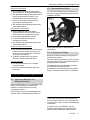
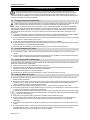
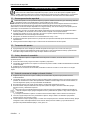
4. Bedienungs- und Funktionsteile
5. Technische Daten
Hacksterne Anzahl / Durchmesser Ø mm 2 / 220
Arbeitsbreite mm 150
Schutzbreite mm 160
Getriebeuntersetzung 1:49
Schaftrohr Werkstoff / Durchmesser Ø mm Aluminium / 24
Antriebswelle Ø mm 7 mm
Sternverzahnung 7 Zahn
Abmessungen Höhe / Breite / Länge mm 260 / 160 / 910
Gewicht kg 2,85
Fig. 1
1 Schutz
2 Hacksterne
3 Befestigung Hacksterne
4 Winkelgetriebe
5 Öffnungsschraube zur
Schmiermittel Nachfüllung

Arbeitsvorbereitung - Anbau ; Anwendung
DEUTSCH 6
6. Arbeitsvorbereitung - Anbau
Vor der Montage (und späteren Demontage) des
Gerätes Anbau
Bodenkultivator ist der Motor
der Motorsense abzustellen und der
Zündkerzenstecker abzuziehen.
Der Anbau
Bodenkultivator mit vormontiertem
Schaftrohrunterteil ist ausschließlich zur
Montage an die SOLO Motorsensen 129LTS
und 129BTS jeweils mit teilbarem Schaft
vorgesehen.
Durch einfaches Austauschen der
Schaftrohrunterteile mit montiertem Werkzeug
ist hier ein einfacher, schneller
Werkzeugwechsel ermöglicht.
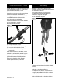
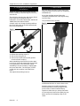
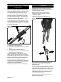
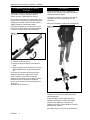
Zum Trennen der beiden Schafthälften:
x Die Spannschraube (1) lösen.
x Den Fixierstift (2) durch Ziehen entriegeln.
x Die untere Schaftrohrhälfte (3) mit
Antriebswelle aus der Kupplungsmuffe
herausziehen.
Beim Zusammenbau ist zu beachten, dass die
Hohlwelle im Schaftrohr-Unterteil in den
Vierkant im Antriebswellen-Oberteil eingreift.
Gegebenenfalls muss beim Zusammenstecken
das Schaftrohrunterteil leicht hin und her
gedreht werden. Der Fixierstift (2) muss in der
Bohrung im Schaftrohr hörbar einrasten.
Danach Spannschraube (1) festziehen.
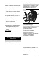
7. Anwendung
Beachten Sie beim Starten des Motors des
komplett montierten Gerätes und beim Arbeiten
die Sicherheitsvorschriften.
Den Tragegurt anlegen und das komplett
montierte Gerät mit laufendem Motor im
Standgas am Tragegurt einhängen.
Nur bei der Arbeit Gasgeben.
Mit dem Bodenkultivator können Sie vorwärts,
rückwärts und abwechselnd nach beiden Seiten
arbeiten.
Den Arbeitsbereich (Hacksterne und Schutz)
während der Arbeit regelmäßig von
verfangenem Gras, Unkraut, anhaftender Erde
oder sonstigen aufgewickelten Rückständen
reinigen. Dabei unbedingt den Motor abstellen
und den Zündkerzenstecker abziehen
Nicht im Schleifbereich der Kupplung arbeiten.
Fig. 2
Fig. 3

Anwendung ; Betriebs- und Wartungshinweise
DEUTSCH 7
Erdkruste aufbrechen
x Gras, Unkraut und sonstige Pflanzenteile
grob entfernen (z. B. mit einem Rasenmäher).
x Zum Bearbeiten festen Bodens eignet sich am
besten das abwechselnd Vorwärts- und
Rückwärtsführen des Hackwerkzeuges.
x Immer nur einen kleinen Bereich bis zur
gewünschten Tiefe bearbeiten.
x Zum Abschluss den bearbeiteten Boden mit
einem Rechen ebnen.
Bodenzusätze einarbeiten
x Humus, Kompost, Laub oder andere
organische Stoffe können mit dem Anbau
Bodenkultivator eingearbeitet werden.
x Bodenzusätze gleichmäßig verteilen.
x In abwechselnden Richtungen das
Hackwerkzeug führen.
x Zum Abschluss den bearbeiteten Boden mit
einem Rechen ebnen.
Boden in Kulturen auflockern
x Nur oberflächlich den Boden um die Pflanzen
herum auflockern. Achten Sie darauf nicht
durch ein zu tiefes Auflockern die Wurzeln
der Pflanzen zu verletzen.
x Um Bäume und Sträucher mit festeren
Wurzeln ausreichend Abstand halten.
Furchen anlegen
x Den Anbau Bodenkultivator langsam
rückwärts ziehen.
x Für tiefere Furchen den Boden mehrmals
bearbeiten.
8. Betriebs- und Wartungshinweise
8.1 Allgemeine Betriebs- und
Wartungshinweise
Nach einer Einlaufzeit von ca. 5 Betriebsstunden
müssen alle erreichbaren Schrauben und
Muttern auf Festsitz überprüft und evtl.
nachgezogen werden.
Kontrollieren Sie vor jedem Arbeitsbeginn das
gesamte Gerät auf betriebssicheren Zustand.
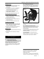
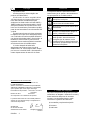
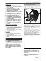
8.2 Schmiermittel einfüllen
Ca. alle 20 Betriebsstunden das Getriebe mit ca.
20 g SOLO "Spezial-Getriebe-Fließfett" (Best.-Nr.
0083180) nachfüllen.
Öffnungsschraube(5) zur Schmiermittel
Nachfüllung.
8.3 Reinigung und Pflege
Beachten Sie bei der Reinigung und Pflege die
Sicherheitsvorschriften.
Nach der Arbeit das gesamte Gerät von Schmutz
und Erde reinigen. Keine lösungsmittelhaltigen
Reinigungsmittel verwenden.
Die Hacksterne nach der Reinigung mit einem
Korrosionsschutzmittel behandeln.
Bei Stilllegung und Aufbewahrung unbefugten
Zugang - besonders durch Kinder - ausschließen.
Im Interesse der ständigen Weiterentwicklung
unserer Geräte müssen wir uns Änderungen des
Lieferumfangs in Form, Technik und Ausstattung
vorbehalten.
Wir bitten auch um Verständnis, dass aus
Angaben und Abbildungen dieser Anleitung
keine Ansprüche abgeleitet werden können.
Fig. 4

ENGLISH 2
Preface
Dear Customer,
Congratulations for choosing this SOLO
quality product.
The cultivator attachment 69 00 150 is
delivered with a pre-assembled lower shaft tube.
It is solely designed for installation on SOLO
brushcutters 129LTS and 129BTS, both with
sectional shaft. A simple, quick tool change is
made possible as the lower shaft tube can be
replaced with the tool head attached.
These instructions will only show the
additional aspects for use of the base tool and
the attached cultivator as opposed to the
instructions detailing the use of the brushcutter.
Basically, all the instructions for the brushcutter
are to be taken into account, in particular the
safety instructions.
We wish you many years of problem free,
successful work.
If, after having read both these instructions
and those of the brushcutter you still have
questions, then please contact your local SOLO
dealer or our service department directly.
CE Declaration of conformity
SOLO Kleinmotoren GmbH, Stuttgarter Str. 41,
D-71069 Sindelfingen,
hereby declares that the following machine, to which
this declaration refers, meets the requirements of the
EC Directives 98/37/EC, 2000/14/EC and 89/336/EEC (as
amended by 92/31/EEC)
Product designation: Cultivator attachment
Model/type: 69 00 150
meets the requirements of the Machinery Directive.
This declaration of conformity loses its validity, if the
equipment is converted or modified without the
manufacturer's consent.
Sindelfingen,
1
st
January 2005
SOLO Kleinmotoren GmbH Wolfgang Emmerich
Executive Director
Symbols
The following symbols are used in these
instructions and on the tool which are additional
to the symbols used on the brushcutter:
Always handle this tool with particular
care
Read these instructions and the
brushcutter instructions
Keep feet away from the operational
area of the cultivator
Before any cleaning or maintenance
work switch off engine and remove
spark plug cap
Never touch rotating blades. Always
switch off the engine and remove
spark plug cap, before any contact
with the blades
1. Parts subject to wear and tear
Various parts are subject to application-specific
or normal wear and must be replaced in good
time, when required. The following parts are
subject to normal wear and are not covered by
the manufacturer's guarantee:
x Tilling blades and their fasteners
x Protection
x Lubricants

ENGLISH 3
Index
Page
1. Parts subject to wear and tear........................................................................................ 2
2. Guarantee ......................................................................................................................... 3
3. Safety regulations............................................................................................................ 4
3.1 General safety instructions 4
3.2 Transporting the tool 4
3.3 Before and during starting 4
3.4 Before commencing work and when hedge trimming 4
4. Control and function elements ....................................................................................... 5
5. Specification ..................................................................................................................... 5
6. Preparation for work – Installation ................................................................................ 6
7. Application........................................................................................................................ 6
8. Operating and maintenance information ...................................................................... 7
8.1 General operating and maintenance instructions 7
8.2 Topping up lubricant 7
8.3 Cleaning and maintenance 7
2. Guarantee
The manufacturer guarantees trouble-free quality and will cover the cost of replacing parts which are
found to be faulty in material or workmanship within the prescribed guarantee period after the date of
purchase. Please note that specific guarantee conditions may vary from country to country. If in doubt,
ask your equipment vendor. He is responsible for guarantee matters.
We hope you will understand that we cannot be liable for damage resulting from the following causes:
x Non-compliance with the operating instructions.
x Neglecting essential maintenance and repair work.
x Damage caused by incorrect carburettor adjustment.
x Wear in normal use.
x Obvious overload by continuously exceeding the maximum performance limit of the product.
x Using non-authorised tools.
x Use of force, incorrect treatment, misuse and accidents.
x Damage from excessive heat due to dirt build-up around the cooling fan housing.
x Attempted adjustments and repairs by unqualified persons.
x Use of unsuitable spare parts or third party parts, if these are the cause of the defect.
x Damage caused by using the product in the hire or rental industry.
Normal cleaning, adjustments or maintenance work fall outside the guarantee provisions.
A service centre authorised by the manufacturer must carry out all guarantee work.

Safety regulations
ENGLISH 4
3. Safety regulations
Always observe all general and safety instructions in this manual and those in the operating instructions of
the brushcutter used. Generally, all the brushcutter instructions and regulations also apply when using the
attachment. The following safety instructions apply additionally to the safety instructions detailed in the
brushcutter manual.
3.1 General safety instructions
Use this tool with care. The cutting blades work at high velocity and have a wide range due to the brushcutter
shaft length.
Ignoring the safety instructions can result in loss of life. Also observe the accident prevention requirements of your
professional body or the Health and Safety at Work Act. Both these instructions and those of the brushcutter must
always be available on site. They must be read by each person who comes into contact with the tool (even for service
and maintenance, care and when replacing parts).
x Only attach the cultivator attachment to SOLO brushcutters 129LTS and 129BTS. The use of this attachment is not
permitted on any other power tool equipment.
x Before you work with this cultivator attachment for the first time, it is advisable to ask your dealer to show and
explain to you the safe handling of this equipment.
x The tool must only be used for the type of work detailed in chapter 7 "Utilisation".
x Only use accessories and spare parts (particularly tilling blades) recommended by the manufacturer.
x Always wear safety gloves when working, cleaning or maintaining the attachment.
3.2 Transporting the tool
x Always switch off the engine before transporting the tool, even when transporting from one work area to the
other by foot.
x The power tool is perfectly balanced when carried by the shaft with tool head facing backwards. Prevent all
contact with the hot silencer.
3.3 Before and during starting
In addition to checking that the power tool is safe for operation, check the following points before starting:
x tight, secure installation of the attachment and the protective shield
x excellent condition of the complete attachment and tilling blades. replace damaged or blunt tilling blades
immediately.
x adequate lubrication.
When starting, the tilling blades must not come into contact with any object neither must they touch the ground.
3.4 Before commencing work and when hedge trimming
x Clear unauthorised people from the working area.
x Before beginning work check the working area. Remove, stones, metal pieces and other hard objects that could
be flung up whilst working. Take extreme care when working in the vicinity of tree roots, dense areas and close
to fences.
x Never use this power tool where there are underground or ground level cables or pipe work.
x Switch off engine and remove spark plug cap before modifying the attachment, for example when cleaning or
refilling the lubricant.
Never touch the tilling blades when the engine is running. If the tilling blades are obstructed by an object,
immediately switch off the engine and remove the spark plug cap. Only then is it safe to clear the object
from the tilling blades.
x Always hold the power tool with both hands when working. Use the shoulder strap.
x Regularly clean the tool (tilling blades and protective shield) by clearing clogged earth or similar materials during
operation. When doing this, always first switch off the engine and remove the spark plug cap.
x Take care not to trip up on tree stumps or roots.
x Immediately switch off the engine in dangerous situations or when people or animals enter the working area. Be
especially aware when wearing ear defenders, as warning sounds (i.e screams etc) are more difficult to hear.

Control and function elements; Specification
ENGLISH 5
4. Control and function elements
5. Specification
Tilling blades Number/diameter Ø mm 2 / 220
Working width mm 150
Shield width mm 160
Gear reduction ratio 1:49
Shaft tube material/diameter Ø mm Aluminium / 24
Drive shaft Ø mm 7 mm
Star gear 7 teeth
Dimensions height/width/length mm 260 / 160 / 910
Weight kg 2,85
Fig. 1
1 Protection
2 Tilling blades
3 Tilling blade fixings
4 Angular gear
5 Open this screw to replenish
low-viscosity greace for gears

Preparation for work – Installation; Application
ENGLISH 6
6. Preparation for work –
Installation
Switch off engine and remove spark plug cap
before installing (or dismantling) the cultivator
attachment.
The cultivator attachment with factory fitted
lower shaft tube is designed solely for
installation on the SOLO brushcutter 129LTS and
129BTS, both with sectional shaft.
A simple, quick tool change is made possible as
the lower shaft tube can now be replaced with
the tool head attached.
To separate the shaft sections:
x Release the straining screw (1).
x Pull out the fixing pin (2).
x Pull the lower shaft tube (3) with gearbox
from the female coupling.
When assembling ensure that the hollow shaft
in the lower shaft tube mates with the quadrant
in the upper part of the drive shaft. When
assembling it may be necessary to lightly jiggle
the lower shaft tube. The fixing pin (2) must
audibly lock into position in the shaft tube
holes.
Ten tighten the straining screw (1).
7. Application
Note the safety instructions when starting the
engine and when working with the completely
assembled tool.
Put on the shoulder strap and hang the
completely assembled tool, with engine idling,
onto the strap.
Only accelerate when working.
It is possible to work the cultivator in a forward
and backward motion or even to side to side.
Regularly clean the tool (tilling blades and
protective shield) by clearing clogged earth,
grass, weeds or similar materials during
operation. When doing so, always first switch
off the engine and remove the spark plug cap.
Never operate in the slipping range of the
clutch.
Fig. 2
Fig. 3

Application ; Operating and maintenance information
ENGLISH 7
Breaking up soil
x Roughly remove any grass, weeds or other
plant material (for example with a
lawnmower).
x For operation in hard soil it is advisable to
alternatively work the tool blades in a
forward and backward motion.
x Always work on a small area until the
required depth is achieved.
x Level off the cultivated area with a rake.
Working substances into the soil
x Humus, compost, leaves or other organic
matter can be worked into the soil with the
cultivator attachment.
x Evenly distribute the matter.
x Cultivate the area by moving the blades in
alternate directions.
x Level off the cultivated area with a rake.
Loosening soil in borders
x Only loosen the top layer of the soil around
plants. Take care not to damage the plant
roots by cultivating too deeply.
x Maintain a safe distance around trees and
bushes with more substantial roots.
Making furrows
x Slowly pull the cultivator attachment through
the ground.
x Work the soil more frequently for deeper
furrows.
8. Operating and maintenance
information
8.1 General operating and
maintenance instructions
After a running-in time of app. 5 hours, all
accessible screws and nuts (except the
carburettor adjusting screws) must be checked
for tightness and they must be retightened, if
required.
8.2 Topping up lubricant
Refill the gearbox with SOLO "Special gearbox
flow grease" (part no. 00831180) approx. Every
20 operating hours.
Open screw (5) to replenish low-viscosity greace
for gears.
8.3 Cleaning and maintenance
Observe the safety instructions when cleaning
and maintaining.
Following operation ensure that the tool is clean
and free of soil. Never use cleaning solutions
containing solvents.
After cleaning treat the tilling blades with a
corrosion inhibitor.
Restrict access to the tool when in storage and
not being used. Keep away from children.
In the best interest of continued technological
progress we reserve the right to change the
design and configuration of any product
without prior notice.
For that reason, no claims can be accepted with
reference to text and illustrations in this manual.
Fig. 4

FRANÇAIS 2
Préface
Chère cliente, cher client
Merci d'avoir porté votre dévolu sur le
présent produit de qualité SOLO.
La houe-bineuse additionnelle 69 00 150
est livrée avec la partie inférieure du tube de
transmission prémontée. Elle est prévue
exclusivement pour être montée sur les
débroussailleuses SOLO 129LTS et 129BTS à
tube de transmission démontable. Le
changement d’outil est plus simple et rapide car
il suffit ici de remplacer les parties inférieures de
tube de transmission sur lesquelles un outil est
déjà monté.
Ces instructions ne présentent que les
aspects supplémentaires pour lesquels
l’utilisation de l’engin de base équipé de la
houe-bineuse additionnelle diffère de
l’utilisation d’origine de la débroussailleuse. Par
principe, toutes les indications données dans les
instructions de la débroussailleuse doivent être
respectées, ceci vaut tout particulièrement pour
les consignes de sécurité.
Nous vous souhaitons de nombreuses années
d’une utilisation sans problème et couronnée de
succès.
Si vous aviez d’autres questions après avoir
lu attentivement ces instructions ainsi que les
instructions de la débroussailleuse, veuillez vous
adresser à votre revendeur SOLO ou bien
directement à notre service après-vente.
CE Déclaration de conformité
SOLO Kleinmotoren GmbH, Stuttgarter Str. 41,
D-71069 Sindelfingen,
déclare que, selon les directives CE 98/37/CE,
2000/14/CE et 89/336/CEE (modifiée par 92/31/CEE),
l’engin suivant, dans l’exécution livrée
Désignation du produit :
Houe-bineuse additionnelle
Désignation de série/de modèle : 69 00 150
satisfait aux exigences de la directive sur les machines.
Cette attestation de conformité perd sa validité dès
que le produit est transformé ou modifié sans accord
préalable
Sindelfingen,
le 01 Janvier 2005
SOLO Kleinmotoren GmbH Wolfgang Emmerich
P.D.G
Symboles
Les symboles suivants sont utilisés dans les
présentes instructions et sur l’engin en plus des
symboles utilisés sur la débroussailleuse:
Utiliser la débroussailleuse avec une
attention particulière
Lire ces instructions ainsi que les
instructions de la débroussailleuse
N’introduisez jamais le pied dans la
zone de travail de l’outil
Coupez le moteur avant toute
opération de maintenance ou de
nettoyage et déconnectez la cosse de
bougie d’allumage
N’introduisez jamais la main dans la
zone de rotation de la lame. Avant de
toucher la lame (même pour un simple
nettoyage), coupez toujours le moteur
et déconnectez la cosse de bougie
d’allumage
1. Pièces d’usure
Différentes pièces sont sujettes à l'usure normale
ou due à l'utilisation et doivent être remplacées
à temps, si nécessaire. Les pièces d'usure
indiquées ci-dessous ne sont pas couvertes par la
garantie du fabricant:
x Brise-mottes et éléments de fixation des
brise-mottes
x Protection
x Lubrifiants

FRANÇAIS 3
Sommair
Page
1. Pièces d’usure ................................................................................................................... 2
2. Garantie............................................................................................................................. 3
3. Consignes de sécurité ...................................................................................................... 4
3.1 Consignes de sécurité générales 4
3.2 Lors du transport de l’engin 4
3.3 Avant et pendant le démarrage 4
3.4 Avant le début du travail 4
4. Organes de commande et éléments fonctionnels......................................................... 5
5. Caractéristiques techniques ............................................................................................ 5
6. Préparation du travail – montage d’équipement.......................................................... 6
7. Utilisation.......................................................................................................................... 6
8. Remarques d’exploitation et de maintenance............................................................... 7
8.1 Instructions d'utilisation générales 7
8.2 Remplissage de lubrifiant 7
8.3 Reinigung und Pflege 7
2. Garantie
Le fabricant garantit une qualité irréprochable et prend en charge les frais d’amélioration occasionnés
par un remplacement de pièces défectueuses en cas de défaut du matériau ou de la fabrication survenant
durant la période de garantie. Notez que certains pays possèdent des conditions de garantie
particulières. En cas de doute, interrogez votre revendeur. En tant que vendeur du produit, il est
responsable de la garantie.
Nous ne pouvons assurer de garantie pour les dommages engendrés par les causes suivantes, merci de
votre compréhension :
x Non-respect du manuel d’utilisation.
x Travaux de maintenance et de nettoyage négligés.
x Usure due à une utilisation normale.
x Surcharge évidente due à un dépassement prolongé de la limite de puissance maximale.
x Utilisation d’outils de travail non autorisés.
x Emploi de la force, mauvais traitement, abus ou accident.
x Dommage de surchauffe dû à un encrassement du carter du ventilateur.
x Intervention de personnes non qualifiées ou tentatives de réparation non professionnelles.
x Utilisation de pièces de rechange non adaptées ou non originales qui ont causé le dommage.
x Dommages imputables aux conditions d’utilisation dans le cadre de la location.
Les travaux de nettoyage, d’entretien et de réglage ne sont pas reconnus comme des prestations de
garantie.
Tous les travaux de garantie doivent être réalisés par le distributeur spécialisé agréé par le fabricant.

Consignes de sécurité
FRANÇAIS 4
3. Consignes de sécurité
Respectez impérativement les instructions et consignes de sécurité contenues dans le présent manuel
d’utilisation ainsi que dans le manuel d’utilisation de la débroussailleuse utilisée. Par principe, toutes les
remarques et consignes contenues dans le manuel d’utilisation de la débroussailleuse valent aussi pour
l’utilisation de l’engin additionnel. Les consignes de sécurité suivantes valent en plus des indications données dans
le manuel d’utilisation de la débroussailleuse.
3.1 Consignes de sécurité générales
Utilisez cet engin avec la plus grande prudence à cause des vitesses de lame élevées lors du travail et du rayon
d’action important de la lame dû à la longueur du tube de transmission de la débroussailleuse.
Le non-respect des consignes de sécurité peut entraîner la mort. Respectez également les consignes de prévention
d’accident des caisses de prévoyance des accidents. Le présent manuel d’utilisation et le manuel d’utilisation de la
débroussailleuse doivent toujours être disponibles sur le lieu d’utilisation. Ils doivent être lus par toute personne
devant effectuer des travaux avec ou sur l’engin (même s’il s’agit de travaux de maintenance, d’entretien ou de
réparation).
x La houe-bineuse additionnelle doit exclusivement être montée sur les débroussailleuses SOLO 129LTS et 129BTS.
L’utilisation de cet engin additionnel sur d’autres engins à moteur de base n’est pas autorisée.
x Si c’est la première fois que vous travaillez avec une houe-bineuse additionnelle, faites-vous montrer et expliquer
par le vendeur comment l’utiliser de façon sûre.
x L’engin doit être utilisé exclusivement dans le but indiqué au chapitre 7 « Utilisation ».
x Seuls des accessoires et pièces de rechange (particulièrement pour les brise-mottes) expressément recommandés
par le fabricant pour cet appareil doivent être utilisés.
x Portez des gants de protection pour le travail, le nettoyage et tous les travaux de maintenance.
3.2 Lors du transport de l’engin
x Lors de chaque transport – même pour le transport à pied d’un lieu de travail à l’autre – coupez toujours le
moteur.
x L’engin à moteur doit être porté par le tube de transmission de façon équilibrée, l’outil de travail pointant vers
l’arrière. Veillez à ce que le silencieux brûlant ne vous touche pas.
3.3 Avant et pendant le démarrage
Après avoir vérifié que l’ensemble de l’engin à moteur est en état de fonctionner de façon sûre, les points suivants
doivent être contrôlés avant le démarrage :
x Montage fixe et sûr de l’engin additionnel et de la protection
x Les brise-mottes et l’ensemble de l’engin additionnel sont dans un état irréprochable. Les brise-mottes
défectueux ou émoussés doivent être remplacés immédiatement.
x Du lubrifiant a été appliqué en quantité suffisante
Lors du démarrage, les brise-mottes ne doivent être en contact avec aucun objet ni avec le sol.
3.4 Avant le début du travail
x Avant de commencer le travail, assurez qu’aucune personne ne pourra s’introduire à proximité de la zone de
travail sans être remarquée.
x Contrôlez le terrain avant le travail. Retirez les pierres, les morceaux de métal et autres objets durs pouvant être
projetés en l’air. Travaillez avec une prudence toute particulière dans la zone des racines d’arbres, dans les
terrains à végétation touffue et à proximité des clôtures.
x Si des câbles ou des conduites sont posés dans ou sur le sol, l’engin à moteur ne doit pas être utilisé.
x Avant toute modification sur l’engin additionnel (p.ex. nettoyage, rajout de lubrifiant), coupez toujours d’abord
le moteur et déconnectez la cosse de bougie d’allumage.
Ne touchez jamais aux brise-mottes lorsque le moteur tourne. Si les brise-mottes sont bloqués par un objet,
coupez immédiatement le moteur et déconnectez la cosse de bougie d’allumage, retirez seulement ensuite
l’objet de la zone de travail.
x Tenez toujours l’engin fermement à deux mains pendant le travail. Utilisez un harnais.
x Durant le travail, retirez régulièrement la terre ou toute autre matière collant dans la zone de travail (brise-
mottes et protection). Pour cela, coupez impérativement le moteur et déconnectez la cosse de bougie
d’allumage.
x Prêtez attention aux obstacles et aux objets sur lesquels vous pourriez buter tels que les souches d’arbre ou les
racines.
x En cas de danger imminent ou lorsque des personnes ou des animaux s’approchent de la zone de travail, coupez
immédiatement le moteur. Si vous portez une protection acoustique, soyez particulièrement attentif, la
perception de bruits annonçant un danger (cris, etc.) étant limitée.

Organes de commande et éléments fonctionnels ; Caractéristiques techniques
FRANÇAIS 5
4. Organes de commande et éléments fonctionnels
5. Caractéristiques techniques
Brise-mottes Nombre/diamètre Ø mm 2 / 220
Largeur de travail mm 150
Largeur de protection mm 160
Réduction de l’engrenage 1:49
Tube de transmission matériau/diamètre Ø mm Aluminium / 24
Arbre d’entraînement Ø mm 7 mm
Denture en étoile 7 dents
Dimensions hauteur/largeur/longueur mm 260 / 160 / 910
Poids kg 2,85
Fig. 1
1 Protection
2 Brise-mottes
3 Fixation de brise-mottes
4 Engrenage angulaire
5 Vis de remplissage lubrifiaut

Préparation du travail – montage d’équipement ; Utilisation
FRANÇAIS 6
6. Préparation du travail – montage
d’équipement
Avant le montage (et plus tard, le démontage)
de la houe-bineuse additionnelle, le moteur
de la débroussailleuse doit être coupé et la cosse
de bougie d’allumage doit être déconnectée.
La houe-bineuse additionnelle avec partie
inférieure de tube de transmission prémontée
est prévue exclusivement pour être montée sur
les débroussailleuses SOLO 129LTS et 129BTS
à tube de transmission démontable.
Le changement d’outil est plus simple et rapide
car il suffit maintenant de remplacer les parties
inférieures de tube de transmission sur lesquelles
un outil est déjà monté.
Pour séparer les deux moitiés du tube :
x Desserrez la vis de serrage (1).
x Débloquez la goupille de fixation (2) en tirant
dessus.
x Tirez la moitié inférieure du tube de
transmission avec l’arbre d’entraînement hors
du manchon d’accouplement (3).
Lors de l’assemblage, il faut veiller à ce que
l’arbre creux de la partie inférieure du tube de
transmission s’engrène dans le carré de la partie
supérieure de l’arbre d’entraînement. Le cas
échéant, faites faire de légers mouvements de
rotation à la partie inférieure du tube de
transmission lors de l’assemblage. La goupille de
fixation (2) doit s’encliqueter audiblement dans
l’alésage du tube de transmission.
Serrez ensuite fermement la vis de serrage (1).
7. Utilisation
Respectez les consignes de sécurité lors du
démarrage du moteur de l’engin entièrement
monté et pendant le travail.
Mettez le harnais et accrochez l’engin
entièrement monté au harnais, le moteur
tournant au ralenti.
Accélérez uniquement pendant le travail.
La houe-bineuse vous permet de travailler en
avançant, en reculant et sur les deux côtés
alternativement.
Durant le travail, retirez régulièrement l’herbe
prise, les mauvaises herbes, la terre collée ou
tout autre résidu enroulé dans la zone de travail
(brise-mottes et protection). Pour cela, coupez
impérativement le moteur et déconnectez la
cosse de bougie d’allumage
Ne travaillez pas en régime de frottement du
dispositif d’accouplement.
Fig. 2
Fig. 3

Utilisation ; Remarques d’exploitation et de maintenance
FRANÇAIS 7
Briser la croûte de terre
x Retirez grossièrement l’herbe, les mauvaises
herbes ou autres parties de végétaux (avec
une tondeuse p.ex.).
x Pour travailler un sol dur, la méthode la
mieux adaptée est de faire avancer et reculer
alternativement l’outil brise-mottes.
x Traitez toujours une petite surface à la fois
jusqu’à atteindre la profondeur souhaitée.
x Ratissez ensuite le sol traité pour l’aplanir.
Incorporer des additifs pour le sol
x Il est possible d’incorporer de l’humus, du
compost, des feuilles mortes ou d’autres
matières organiques à l’aide de la houe-
bineuse additionnelle.
x Répartissez les additifs pour le sol
uniformément.
x Guidez la houe-bineuse dans différentes
directions alternativement.
x Ratissez ensuite le sol traité pour l’aplanir.
Ameublir le sol de cultures
x N’ameublissez le sol autour des plantes que
de façon superficielle. Veillez à ne pas
endommager les racines des plantes en
ameublissant trop profondément.
x Maintenez un écart suffisant des arbres et des
buissons.
Tracer des sillons
x Tirez la houe-bineuse additionnelle
lentement vers l’arrière.
x Pour des sillons plus profonds, traitez le sol
plusieurs fois de suite.
8. Remarques d’exploitation et de
maintenance
8.1 Instructions d'utilisation générales
Après un temps de rodage d'environ 5 heures de
service, tous les écrous et vis accessibles (à
l'exception des vis de réglage du carburateur)
doivent être contrôlés et resserrés, si nécessaire.
8.2 Remplissage de lubrifiant
Toutes les 20 heures de service environ, graissez
l’engrenage à l’aide du « lubrifiant liquide
spécial pour engrenage » SOLO (n° cde
0083180).
Vis de remplissage lubrifiaut (5).
8.3 Reinigung und Pflege
Respectez les consignes de sécurité lors du
nettoyage et de l’entretien.
Après le travail, éliminez les saletés et la terre
sur tout l’engin. N’utilisez aucun produit
nettoyant contenant des solvants.
Traitez les brise-mottes avec un produit
anticorrosion après le nettoyage.
En cas de mise hors service et d’entrepôt, veillez
à exclure tout accès non autorisé –
particulièrement par des enfants.
En vue d’une amélioration continuelle de nos
produits, nous nous réservons le droit de
modifier le contenu de la livraison tant en ce qui
concerne la forme que la technologie et
l’équipement.
Les données et illustrations contenues dans les
présentes instructions n’ouvrent aucun droit à
des prétentions quelconques, merci de votre
compréhension.
Fig. 4

ESPAÑOL 2
Prólogo
Apreciado cliente
Muchas gracias por haber elegido este
producto de calidad SOLO
El cultivador de suelos acoplable 69 00
150 viene de serie con la parte inferior de la
barra. Está indicado exclusivamente para
acoplarse a las desbrozadoras SOLO 129LTS y
129BTS, ambas con barra desmontable. Gracias
al simple intercambio de la parte inferior de la
barra con la herramienta ya montada es posible
pasar de una herramienta a otra de manera fácil
y rápida.
En estas instrucciones se incluyen solamente
los aspectos en los que el uso del aparato básico
con el cultivador de suelos acoplable difiere del
uso original de la desbrozadora. En principio, se
tendrán en cuenta los datos y sobre todo se
respetarán las normas de seguridad contenidas
en las instrucciones de la desbrozadora.
Si, incluso después de haber leído
atentamente estas instrucciones y las de la
desbrozadora, Vd. tuviera alguna duda, diríjase
por favor a su comercial SOLO o directamente a
nuestro departamento de atención al cliente.
CE Declaracion de conformidad
SOLO Kleinmotoren GmbH, Stuttgarter Str. 41,
D-71069 Sindelfingen,
declara conforme a la normativa europea 98/37/CE,
2000/14/CE y 89/336/CE (modificada por la 92/31/CE),
que el aparato aquí citado, según se entrega:
Denominación del producto: Cultivador de suelos
acoplable
Número de serie: 69 00 150
se corresponde con la definición del aparato.
La presente declaración de conformidad perderá su
vigencia en caso de desmontaje o manipulación no
autorizada del producto
Sindelfingen,
01 de enero de 2005
SOLO Kleinmotoren GmbH Wolfgang Emmerich
Director
Símbolos
Los siguientes símbolos aparecerán en estas
instrucciones y en el aparato, adicionalmente a
los que aparecían en la desbrozadora:
Sea especialmente cuidadoso en el
manejo de la máquina
Lea estas instrucciones además de las
instrucciones de la desbrozadora
No ponga nunca el pie al alcance de la
herramienta
Antes de realizar cualquier tarea de
limpieza o mantenimiento apague el
motor y desenchufe el aparato
No toque nunca las cuchillas mientras
estén girando. Antes de entrar en
cualquier tipo de contacto con las
cuchillas (incluso la simple limpieza de
las mismas), apague siempre el motor y
desenchufe el aparato
1. Piezas de desgaste
Hay varios componentes del aparato que están
sometidos a un desgaste o al deterioro normal y
deben sustituirse siempre en el momento
oportuno. Las siguientes piezas no están
incluidas en la garantía del fabricante:
x Las estrellas y sus piezas de sujeción
x Protector
x Lubricante
Seite wird geladen ...
Seite wird geladen ...
Seite wird geladen ...
Seite wird geladen ...
Seite wird geladen ...
Seite wird geladen ...
Seite wird geladen ...
Seite wird geladen ...
-
 1
1
-
 2
2
-
 3
3
-
 4
4
-
 5
5
-
 6
6
-
 7
7
-
 8
8
-
 9
9
-
 10
10
-
 11
11
-
 12
12
-
 13
13
-
 14
14
-
 15
15
-
 16
16
-
 17
17
-
 18
18
-
 19
19
-
 20
20
-
 21
21
-
 22
22
-
 23
23
-
 24
24
-
 25
25
-
 26
26
-
 27
27
-
 28
28


in anderen Sprachen
- English: Solo 69 00 150 User manual
- français: Solo 69 00 150 Manuel utilisateur
- español: Solo 69 00 150 Manual de usuario