G&D DVISplitter2-DL Installationsanleitung
- Kategorie
- Video-Splitter
- Typ
- Installationsanleitung

G&D DVISplitter2-DL
DE Installationsanleitung
EN Installation Guide
Guntermann & Drunck GmbH
www.gdsys.de
A9100204-1.00

i · G&D DVISplitter2-DL
Zu dieser Dokumentation
Diese Dokumentation wurde mit größter Sorgfalt erstellt und nach dem Stand der
Technik auf Korrektheit überprüft.
Für die Qualität, Leistungsfähigkeit sowie Marktgängigkeit des G&D-Produkts zu
einem bestimmten Zweck, der von dem durch die Produktbeschreibung abgedeck-
ten Leistungsumfang abweicht, übernimmt G&D weder ausdrücklich noch still-
schweigend die Gewähr oder Verantwortung.
Für Schäden, die sich direkt oder indirekt aus dem Gebrauch der Dokumentation
ergeben, sowie für beiläufige Schäden oder Folgeschäden ist G&D nur im Falle des
Vorsatzes oder der groben Fahrlässigkeit verantwortlich.
Gewährleistungsausschluss
G&D übernimmt keine Gewährleistung für Geräte, die
nicht bestimmungsgemäß eingesetzt wurden.
nicht autorisiert repariert oder modifiziert wurden.
schwere äußere Beschädigungen aufweisen, welche nicht bei Lieferungserhalt
angezeigt wurden.
durch Fremdzubehör beschädigt wurden.
G&D haftet nicht für Folgeschäden jeglicher Art, die möglicherweise durch den
Einsatz der Produkte entstehen können.
Warenzeichennachweis
Alle Produkt- und Markennamen, die in diesem Handbuch oder in den übrigen
Dokumentationen zu Ihrem G&D-Produkt genannt werden, sind Warenzeichen
oder eingetragene Warenzeichen der entsprechenden Rechtsinhaber.
Impressum
© Guntermann & Drunck GmbH 2011. Alle Rechte vorbehalten.
Version 1.00 – 06.12.2011
Firmware: 1.0.000
Guntermann & Drunck GmbH
Obere Leimbach 9
57074 Siegen
Germany
Telefon +49 (0) 271 23872-0
Telefax +49 (0) 271 23872-120
http://www.gdsys.de

Inhaltsverzeichnis
G&D DVISplitter2-DL · ii
Inhaltsverzeichnis
Sicherheitshinweise .......................................................................................... 1
Der »DVISplitter2-DL« .................................................................................... 2
Unterstützte Übertragungslängen ..................................................................... 2
Lieferumfang .................................................................................................... 2
Installation ....................................................................................................... 3
Statusanzeigen .................................................................................................. 4
Auswahl der DDC-Information ........................................................................ 5
Transparente Weiterleitung der DDC-Informationen .......................................... 5
Voreingestellte DDC-Profile .............................................................................. 5
DDC-Information eines Monitors auslesen ......................................................... 6
Unterstützte Grafikauflösungen ....................................................................... 7
Technische Daten ............................................................................................. 8

Sicherheitshinweise
1 · G&D DVISplitter2-DL
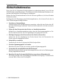
Sicherheitshinweise
Bitte lesen Sie die folgenden Sicherheitshinweise aufmerksam durch, bevor Sie das
G&D-Produkt in Betrieb nehmen. Die Hinweise helfen Schäden am Produkt zu ver-
meiden und möglichen Verletzungen vorzubeugen.
Halten Sie diese Sicherheitshinweise für alle Personen griffbereit, die dieses Produkt
benutzen werden.
Befolgen Sie alle Warnungen oder Bedienungshinweise, die sich am Gerät oder in
dieser Bedienungsanleitung befinden.
, Vorsicht vor Stromschlägen
Um das Risiko eines Stromschlags zu vermeiden, sollten Sie das Gerät nicht öff-
nen oder Abdeckungen entfernen. Im Servicefall wenden Sie sich bitte an unsere
Techniker.
, Ziehen Sie den Netzstecker des Geräts vor Installationsarbeiten
Stellen Sie vor Installationsarbeiten sicher, dass das Gerät spannungsfrei ist. Zie-
hen Sie den Netzstecker oder die Spannungsversorgung am Gerät ab.
, Ständigen Zugang zu den Netzsteckern der Geräte sicherstellen
Achten Sie bei der Installation der Geräte darauf, dass die Netzstecker der
Geräte jederzeit zugänglich bleiben.
! Stolperfallen vermeiden
Vermeiden Sie bei der Verlegung der Kabel Stolperfallen.
, Geerdete Spannungsquelle verwenden
Betreiben Sie dieses Gerät nur an einer geerdeten Spannungsquelle.
, Verwenden Sie ausschließlich das G&D-Netzteil
Betreiben Sie dieses Gerät nur mit dem mitgelieferten oder in der Bedienungsan-
leitung aufgeführten Netzteil.
! Betreiben Sie das Gerät ausschließlich im vorgesehenen Einsatzbereich
Die Geräte sind für eine Verwendung im Innenbereich ausgelegt. Vermeiden Sie
extreme Kälte, Hitze oder Feuchtigkeit.

Der »DVISplitter2-DL«
G&D DVISplitter2-DL · 2
Der »DVISplitter2-DL«
Der DVISplitter2-DL verteilt die Videoübertragung auf zwei Monitore.
Die im DVISplitter2-DL eingehenden Videodaten werden an die angeschlossenen
Monitore übertragen. Die dargestellte Auflösung und Farbtiefe auf den Monitoren
entspricht den Eigenschaften des Eingangssignals.
Unterstützte Übertragungslängen
Eine Übersicht der vom DVISplitter2-DL unterstützten Übertragungslängen finden
Sie auf Seite 8.
Die Mehrzahl der am Markt erhältlichen Grafikkarten erzeugt qualitativ hochwer-
tige Videodaten, welche ohne sichtbare Verluste über die angegebenen Strecken
übertragen werden können.
Einige Grafikkarten erreichen nicht die angegebenen Übertragungslängen. Hierzu
zählen beispielsweise Grafikkarten mit folgenden Chipsätzen:
ATI Radeon X300
Intel GMA950 (Mac mini)
Matrox Millenium G450
Lieferumfang
1 × DVISplitter2-DL
1 × Tischnetzteil 12V/2A
1 × Kaltgeräte-Netzkabel
1 × Videokabel DVI-D-DL-M/M-2
1 × Installationsanleitung
TIPP:
Schließen Sie an den DVISplitter2-DL weitere, baugleiche Geräte an, um die
Anzahl der anschließbaren Monitore und/oder die überbrückbare Entfernung zu
erweitern.
HINWEIS:
Die Videodaten solcher Grafikkarten sind nur bedingt zur Übertragung
über größere Entfernungen geeignet.

Installation
3 · G&D DVISplitter2-DL
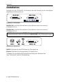
Installation
Schließen Sie das DVI-Kabel, die Monitore und das Netzteil an die nachfolgend
aufgeführten Schnittstellen an.
DVI-D DL Out 1: Schließen Sie wahlweise einen Monitor oder einen weiteren
DVISplitter2-DL an.
DVI-D DL Out 2: Schließen Sie wahlweise einen Monitor oder einen weiteren
DVISplitter2-DL an.
DVI CPU: Schließen Sie das DVI-Kabel der Videoquelle an.
Power In: Schließen Sie das mitgelieferte Tischnetzteil an.
Verbinden Sie anschließend das mitgelieferte Kaltgeräte-Netzkabel mit
dem Tischnetzteil und der Netzspannung.
Abbildung 1: Frontansicht
HINWEIS:
Die Schnittstelle DVI-D DL Out 1 leitet die DDC-Information des ange-
schlossenen Monitors über die Schnittstelle DVI-D DL CPU an die Videoquelle weiter.
Abbildung 2: Rückansicht

Statusanzeigen
G&D DVISplitter2-DL · 4
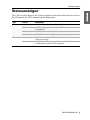
Statusanzeigen
Die LEDs an der Rückseite des Gerätes signalisieren den Betriebsstatus des Gerätes.
Die Blinkmodi der LEDs haben folgende Bedeutung:
LED Status Bedeutung
Status an Am Videoeingang wurde das Signal »DDC-Power« erkannt.
blinkt Am Videoeingang wurde das Signal »DDC-Power«
nicht erkannt.
blinkt schnell Der DDC-Lernmodus ist aktiv.
blitzt Die DDC-Information des Monitors wurde eingelesen.
Power an Das Gerät wird durch das Tischnetzteil mit
Spannung versorgt.
aus Das Tischnetzteil ist nicht angeschlossen oder die Verbindung
zur Netzspannung wurde nicht hergestellt.

Auswahl der DDC-Information
5 · G&D DVISplitter2-DL
Auswahl der DDC-Information
Die Ausgabe des Videosignals auf den Monitoren des DVISplitter2-DL ist nur mög-
lich, wenn das Videosignal und die DDC-Information übertragen werden.
Transparente Weiterleitung der DDC-Informationen
In der Standardeinstellung (Schalterstellung Def.) liest der DVISplitter2-DL die DDC-
Information des angeschlossenen Monitors an der Schnittstelle DVI-D DL Out 1 aus.
Die ausgelesenen DDC-Informationen werden über die Schnittstelle DVI-D DL CPU an
die Videoquelle weitergeleitet.
Kann die DDC-Information – beispielsweise aufgrund eines schwachen DDC-
Signals – nicht über die komplette Strecke übertragen werden, erscheint auf dem
Monitor kein Bild oder die gewünschte Bildauflösung kann nicht eingestellt werden.
In diesem Fall können Sie eines der voreingestellten DDC-Profile aktivieren oder
die DDC-Information eines Monitors im DVISplitter2-DL speichern.
Voreingestellte DDC-Profile
Wählen Sie ein bestimmtes DDC-Profil aus, falls auf dem Monitor kein Bild
erscheint oder die gewünschte Bildauflösung nicht eingestellt werden kann.
Die folgende Tabelle listet die verschiedenen Schalterstellungen und die entspre-
chenden DDC-Profile bzw. Funktionen auf:
TIPP:
Verwenden Sie alternativ den Learn-Modus, um die DDC-Information eines
Monitors auszulesen und zu speichern. Nach der Aktivierung des User-Modus lei-
tet der DVISplitter2-DL diese Informationen an die Videoquelle weiter.

Auswahl der DDC-Information
G&D DVISplitter2-DL · 6
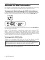
DDC-Information eines Monitors auslesen
Neben der Auswahlmöglichkeit eines voreingestellten DDC-Profils, können Sie die
DDC-Information eines Monitors auslesen und speichern.
Falls ein schwaches DDC-Signal die Übertragung der DDC-Informationen des
Monitors über eine lange Strecke verhindert, kann die Videoquelle so auf die gespei-
cherten DDC-Informationen im DVISplitter2-DL zugreifen.
So lesen Sie die DDC Information eines Monitors aus:
Schalterstellung DDC-Profil/Funktion
Def. Transparente Weiterleitung der DDC-Informationen (Standard)
12560 × 1600 Bildpunkte, 60 Hz (CVT-R)
22560 × 1440 Bildpunkte, 60 Hz (CVT-R)
32048 × 2048 Bildpunkte, 60 Hz (CVT-R)
41920 × 1200 Bildpunkte, 60 Hz (CVT-R)
51920 × 1080 Bildpunkte, 60 Hz (CEA/DMT)
61680 × 1050 Bildpunkte, 60 Hz (CVT)
71280 × 1024 Bildpunkte, 60 Hz (DMT)
User Verwendung der ausgelesenen DDC-Information des Monitors
Learn DDC-Information des Monitors auslesen
1. Ziehen Sie das DVI-Videokabel aus der Schnittstelle DVI-D DL Out 1.
2. Stellen Sie den DDC-Drehschalter auf die Position Learn.
Die Aktivierung des Lernmodus wird an der Status-LED
signalisiert (siehe Statusanzeigen auf Seite 4).
3. Schließen Sie den Monitor, dessen DDC-Information gespeichert werden soll,
an die Schnittstelle DVI-D DL Out 1 an.
Das erfolgreiche Einlesen der DDC-Information wird an den LEDs signalisiert
(siehe Statusanzeigen auf Seite 4).
4. Entfernen Sie das Monitorkabel aus der Schnittstelle DVI-D DL Out 1.
5. Stellen Sie den DDC-Drehschalter auf die Position User.
Die eingelesene DDC-Information wird über die Schnittstelle
DVI-D DL CPU an die Videoquelle übertragen.

Unterstützte Grafikauflösungen
7 · G&D DVISplitter2-DL
Unterstützte Grafikauflösungen
Grundsätzlich unterstützt der DVISplitter2-DL jede Auflösung, die gemäß DVI-Spe-
zifikation übertragen werden kann. Dies betrifft vor allem die Pixelrate, die zwi-
schen 25 und 165 MHz (Single-Link) bzw. 165 und 330 MHz (Dual-Link) liegen darf.
Für die üblichen Timingstandards VESA DMT und VESA SMT sind im Single-Link-
Betrieb Auflösungen zwischen 640 × 480 und 1600 × 1200 Bildpunkten (jeweils bei
60 Hz) möglich.
1920 × 1200 bei 60 Hz werden nach VESA CVT-RB übertragen, 1920 × 1080 Bild-
punkte bei 60 Hz (progressive) nach CEA861.
Im Dual-Link-Betrieb werden zusätzlich unter anderem die Auflösungen
2560 × 1600, 2048 × 2048 und 1920 × 2160 Bildpunkte (jeweils bei 60 Hz) nach
VESA CVT-RB unterstützt.
Innerhalb der genannten Rahmenparameter sind beliebige Bildwiederholraten und
Auflösungen möglich. Welche Bildschirmmodi zur Auswahl stehen, hängt maßgeb-
lich von der Grafikkarte, dem installierten Gerätetreiber sowie dem Betriebssystem
und dem angeschlossenen Monitor ab.
Die von der Videoquelle an den DVISplitter2-DL übertragenen Videodaten werden
unverändert an die Monitore weitergegeben.
HINWEIS:
Viele Grafikkarten unterscheiden bei der Erstellung des Videosignals
nach digitaler und analoger Ausgabe. Solche Grafikkarten erzeugen für den
DVISplitter2-DL digitale Bildsignale.
Dies hat zur Folge, dass einige Grafikkarten – unabhängig von den Grafikeinstel-
lungen innerhalb des Betriebssystems – das Bild auf die am DDC-Drehschalter
gewählte Auflösung des DVISplitters skalieren. Verwenden Sie gegebenenfalls den
DDC-Drehschalter, um die gewünschte (native) Auflösung auszuwählen
(s. Seite 5).

Technische Daten
G&D DVISplitter2-DL · 8
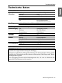
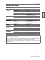
Technische Daten
DVISPLITTER2-DL
Unterstützte
Videodaten Auflösung: max. 2560 × 1600 @ 60 Hz
Farbtiefe: 24 Bit
Videoeingang: 1 x DVI-D (Dual Link)
Videoausgänge: 2 x DVI-D (Dual Link)
DDC: DDC-Information an der
Schnittstelle »DVI-D DL Out 1«
Kabellängen zwischen Videoquelle und Splitter: 2 Meter
zwischen Splittern: 2 Meter
Kakadierung Anzahl Kaskadierungsstufen 3
Stromversorgung Typ: Tischnetzteil (12V/2A)
Anschluss: Mini-DIN 4-Buchse
Stromaufnahme: 12VDC/200 mA
Leistungs-
aufnahme Standby: 40 mA
Betrieb: 180 mA
Gehäuse Material: Aluminium eloxiert
Maße (B x H x T): 105 × 26 × 84 mm
Gewicht: ca. 200 g
Einsatzumgebung Temperatur: +5 bis +40 °C
Luftfeuchte: < 80%, nicht kondensierend
Konformität CE, RoHs
HINWEIS:
Die Kabellängen und die Anzahl der Kaskadierungsstufen sind von der
Qualität des eingehenden Videosignals abhängig.
Tests mit verschiedenen Videoquellen haben große Unterschiede in Bezug auf die
Qualität des Videosignals und der daraus resultierenden Kabellängen und Kaska-
dierungsstufen ergeben.
Die angegebenen Daten stellen Erfahrungswerte dar, die von der Mehrzahl der
getesteten Grafikkarten erreicht wurden.

i · G&D DVISplitter2-DL
About this manual
This manual has been carefully compiled and examined to the state-of-the-art.
G&D neither explicitly nor implicitly takes guarantee or responsibility for the qual-
ity, efficiency and marketability of the product when used for a certain purpose that
differs from the scope of service covered by this manual.
For damages which directly or indirectly result from the use of this manual as well
as for incidental damages or consequential damages, G&D is liable only in cases of
intent or gross negligence.
Caveat Emptor
G&D will not provide warranty for devices that:
Are not used as intended.
Are repaired or modified by unauthorized personnel.
Show severe external damages that was not reported on the receipt of goods.
Have been damaged by non G&D accessories.
G&D will not be liable for any consequential damages that could occur from using
the products.
Proof of trademark
All product and company names mentioned in this manual, and other documents
you have received alongside your G&D product, are trademarks or registered trade-
marks of the holder of rights.
© Guntermann & Drunck GmbH 2011. All rights reserved.
Version 1.00 – 06/12/2011
Firmware: 1.0.000
Guntermann & Drunck GmbH
Obere Leimbach 9
57074 Siegen
Germany
Phone +49 271 23872-0
Fax +49 271 23872-120
http://www.gdsys.de

Contents
G&D DVISplitter2-DL · ii
Table of contents
Safety instructions ............................................................................................ 1
»DVISplitter2-DL« ........................................................................................... 2
Supported transmission lengths ........................................................................ 2
Package contents .............................................................................................. 2
Installation ....................................................................................................... 3
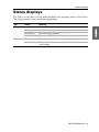
Status displays .................................................................................................. 4
Selecting DDC information .............................................................................. 5
Transparent transmission of DDC information ................................................... 5
Preset DDC profiles ........................................................................................... 5
Reading out a monitor’s DDC information ......................................................... 6
Supported graphic resolutions ........................................................................... 7
Technical data .................................................................................................. 8

Safety instructions
1 · G&D DVISplitter2-DL
Safety instructions
Please read the following safety instructions carefully before you start operating the
G&D product. The instructions well help in avoiding damages to the product and in
preventing possible injuries.
Keep this manual handy for all persons who will be using this product.
Follow all warnings or operating instructions which are on the device or stated in
this user manual.
, Beware of electric shocks
To avoid the risk of electric shock, do not open the device or remove the covers.
If service is required, please contact our technicians.
, Disconnect the main power plug or the power supply before installation
Before installation, ensure that the device has been disconnected from the power
source. Disconnect the main power plug or the power supply of the device.
, Ensure constant access to the power plugs
During the installation of the devices, ensure that the power plugs remain accessible.
! Avoid the risk of tripping over cables
Ensure that there is no risk of tripping over cables.
, Only use a grounded voltage source
Operate this device by using a grounded voltage source.
, Use only the provided G&D power pack
Operate this device with the provided G&D power pack or with the power pack
listed in the manual.
! Operate the device only in designated areas.
The devices are designed for indoor use. Avoid exposure to extreme cold, heat
or humidity.

»DVISplitter2-DL«
G&D DVISplitter2-DL · 2
»DVISplitter2-DL«
DVISplitter2-DL distribute and extend video images to two monitors.
The video data coming in at the DVISplitter2-DL is transmitted to the connected
monitors. Resolution and colour depth at the monitors match the features of the
incoming signal.
Supported transmission lengths
An overview of supported DVISplitter2-DL transmission lengths is given on page 8.
Most recent graphics cards generate high quality video data, which can be transmit-
ted over certain distances without any loss of quality.
Some graphics cards, however, do not reach the given transmission lengths. Among
these are graphics cards with the following chipsets:
ATI Radeon X300
Intel GMA950 (Mac mini)
Matrox Millenium G450
Package contents
1 × DVISplitter2-DL
1 × Portable power pack 12V/2A
1 × IEC cable
1 × video cable DVI-D-DL-M/M-2
1 × Installation Guide
ADVICE:
Connect other identical devices to the DVISplitter2-DL to connect more
monitors and/or increase the distance to be bridged.
NOTE:
Image data of such graphics cards is only partially suited for transmissions
over large distances.

Installation
3 · G&D DVISplitter2-DL
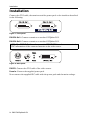
Installation
Connect the DVI cable, the monitors and the power pack to the interfaces described
in the following.
DVI-D DL Out 1: Connect a monitor or another DVISplitter2-DL.
DVI-D DL Out 2: Connect a monitor or another DVISplitter2-DL.
DVI CPU: Connect the DVI cable of the video source.
Power In: Connect the supplied power pack.
Now connect the supplied IEC cable with the power pack and the mains voltage.
Figure 1: Front panel
NOTE:
The DVI-D DL Out 1 interface uses the DVI-D DL CPU interface to transmit the
DDC information of the connected monitor to the video source.
Figure 2: Back panel

Status displays
G&D DVISplitter2-DL · 4
Status displays
The LEDs on the device’s back panel highlight the operating status of the device.
The blinking modes have the following meaning:
LED Status Meaning
Status On Stable »DDC power« signal at video input.
Blinking No »DDC power« signal at video input.
Fast blinking DDC learn mode is enabled.
Flashing The monitor’s DDC information are read in.
Power On The power pack supplies the device with power.
Off The power pack is not connected, or there is no connection to the
mains voltage.

Selecting DDC information
5 · G&D DVISplitter2-DL
Selecting DDC information
The video signal can only be displayed at the monitors of the DVISplitter2-DL if
video signal and DDC information are transmitted.
Transparent transmission of DDC information
In the default settings (switch position Def.), the DVISplitter2-DL uses the DVI-D DL Out 1
interface to read out the DDC information of the connected monitor.
The DVI-D DL CPU interface is used to transmit the read-out DDC information to the
video source.
If the DDC information cannot be transmitted over the entire distance, for example
due to a weak signal, the monitor displays no image or you cannot adjust the pre-
ferred resolution.
In this case, you can enable one of the preset DDC profiles or store the monitor’s
DDC information in the DVISplitter2-DL.
Preset DDC profiles
You can choose a certain DDC profile if the monitor does not display an image or if
you cannot adjust a certain resolution.
The following table lists the different switch positions and the respective DDC pro-
files or functions:
ADVICE:
You can also use the Learn mode to read out and save the monitor’s DDC
information. If you enable the User mode, the DVISplitter2-DL transmits the infor-
mation to the video source.

Selecting DDC information
G&D DVISplitter2-DL · 6
Reading out a monitor’s DDC information
In addition to selecting preset DDC information, you can also read out the DDC
information of a monitor to provide it to the computer.
If the monitor’s DDC information cannot be transmitted over a long distance due to
a weak signal, the video source can access the DDC information stored in the
DVISplitter2-DL.
How to read out DDC information:
Switch position DDC profile/function
Def. Transparent transmission of DDC information (standard)
12560 × 1600 pixels, 60 Hz (CVT-R)
22560 × 1440 pixels, 60 Hz (CVT-R)
32048 × 2048 pixels, 60 Hz (CVT-R)
41920 × 1200 pixels, 60 Hz (CVT-R)
51920 × 1080 pixels, 60 Hz (CEA/DMT)
61680 × 1050 pixels, 60 Hz (CVT)
71280 × 1024 pixels, 60 Hz (DMT)
User Use the monitor’s read-out DDC information
Learn Read out monitr’s DDC information
1. Unplug the DVI-D video cable from the DVI-D DL Out 1 interface.
2. Move the DDC switch to the Learn position.
The status LED shows indicate that the Learn mode is now active
(see Status displays on page 4).
3. Connect the monitor to the DVI-D DL Out 1 interface to store its DDC information.
The LEDs show that the DDC information is read in successfully (see Status
displays on page 4).
4. Remove the monitor cable from the DVI-D DL Out 1 interface.
5. Move the DDC switch to the User position.
The DVI-D DL CPU interface transmits the read-in DDC informa-
tion to the video source.

Supported graphic resolutions
7 · G&D DVISplitter2-DL
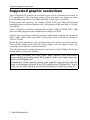
Supported graphic resolutions
The DVISplitter2-DL supports all resolutions that can be transmitted according to
DVI specification. This restriction mainly affects the pixel rate, which can reach
from 25 MHz (single link) to 165 MHz (dual link) or from 165 to 330 MHz.
During single link operation, the common VESA DMT and VESA SMT timing
standards enable resolutions between 640 × 480 pixels at 60 Hz and 1600 × 1200 pix-
els at 60 Hz.
1920 × 1200 pixels at 60 Hz are transmitted according to VESA CVT-RB, 1920 × 1080
pixels at 60 Hz (progressive) are transmitted according to CEA861.
Among other resolutions, dual link operation additionally supports the resolutions
2560 × 1600, 2048 × 2048 and 1920 × 2160 pixels (each at 60 Hz) according to
VESA CVT-RB.
Within the given parameters, you can adjust almost any refresh rate and resolution.
The available display modes depend on the graphics card, the graphics driver, the
operating system and the connected monitor.
The video data that is transmitted from the video source to the DVISplitter2-DL is not
altered when it reaches the monitor.
NOTE:
While generating the video signal, many graphics cards differentiate
between digital and analog output. Such graphics cards create digital image sig-
nals for the DVISplitter2-DL.
Independently of the operating system, some graphics cards therefore scale the
image to the resolution selected at the DDC switch on the DVISplitter2-DL. If nec-
essary, use the DDC switch to select the desired (native) resolution (see page 5).
Seite wird geladen ...
Seite wird geladen ...
Seite wird geladen ...
Seite wird geladen ...
-
 1
1
-
 2
2
-
 3
3
-
 4
4
-
 5
5
-
 6
6
-
 7
7
-
 8
8
-
 9
9
-
 10
10
-
 11
11
-
 12
12
-
 13
13
-
 14
14
-
 15
15
-
 16
16
-
 17
17
-
 18
18
-
 19
19
-
 20
20
-
 21
21
-
 22
22
-
 23
23
-
 24
24


G&D DVISplitter2-DL Installationsanleitung
- Kategorie
- Video-Splitter
- Typ
- Installationsanleitung
in anderen Sprachen
Verwandte Artikel
-
G&D Target Modules Installationsanleitung
-
-
-
-
-
-
-
-
-
