
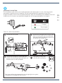
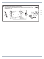
Installation - Installazione - Installation - Montage - Instalación - Montering - Mонтаж
Montáž - Paigaldamine - Εγκατασταση - Beszerelés - Montavimas - Montāža - Instalare
Инсталациjа - Montaż - Установка - Montaža - Montáž - Montaj - Iнсталяція
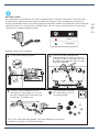
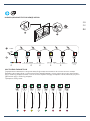
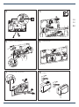
INSTALLATION
1
NO-TOUCH
User manual
Bedienungsanleitung
Инструкция по применению

2
EN
DE
RU
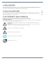
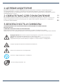
1 - ЦЕЛЕВАЯ АУДИТОРИЯ
2 - ОБЯЗАТЕЛЬНО ДЛЯ ОЗНАКОМЛЕНИЯ
3 - БЕЗОПАСНОСТЬ И СИМВОЛЫ
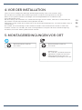
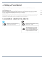
4 - ПЕРЕД УСТАНОВКОЙ
5 - УСЛОВИЯ СБОРКИ НА МЕСТЕ
6 - ИЗДЕЛИЕ
7 - ТЕХНИЧЕСКИЕ ХАРАКТЕРИСТИКИ
8 - ПЕРВОЕ ИСПОЛЬЗОВАНИЕ
9 - ПРИНЦИП ДЕЙСТВИЯ
10 - ФУНКЦИИ И НАСТРОЙКИ
11 - ЭНЕРГИЯ И ДОЛГОВЕЧНОСТЬ
12 - ВЫЯВЛЕНИЕ НЕИСПРАВНОСТЕЙ
13 - УХОД И ТЕХНИЧЕСКОЕ ОБСЛУЖИВАНИЕ
1 - ZIELGRUPPE
2 - PFLICHTLEKTÜRE
3 - SICHERHEIT UND SYMBOLE
4 - VOR DER INSTALLATION
5 - MONTAGEBEDINGUNGEN VOR ORT
6 - PRODUKT
7 - TECHNISCHE SPEZIFIKATION
8 - ERSTE BENUTZUNG
9 - FUNKTIONSPRINZIP
10 - FUNKTIONEN UND EINSTELLUNGEN
11 - ENERGIE UND NACHHALTIGKEIT
12 - FEHLERBEHEBUNG
13 - PFLEGE UND WARTUNG
1 - TARGET AUDIENCE
2 - REQUIRED READING
3 - SECURITY AND SYMBOLS
4 - BEFORE INSTALLATION
5 - ON-SITE ASSEMBLY CONDITIONS
6 - PRODUCT
7 - TECHNICAL SPECIFICATIONS
8 - FIRST USE
9 - PRINCIPLE OF OPERATION
10 - FUNCTIONS AND SETTINGS
11 - ENERGY AND SUSTAINABILITY
12 - TROUBLESHOOT
13 - CARE AND MAINTENANCE
3
3
3
4
4
5
6
6 - 7
8
9 - 12
12
13 - 15
16 - 20
21
21
21
22
22
23
24
24 - 25
26
27 - 30
30
31 - 33
34 - 38
39
39
39
40
40
41
42
42 - 43
44
45 - 48
48
49 - 51
52 - 56

3
1-TARGET AUDIENCE
These assembly instructions are intended for installation companies specializing in sanitary systems with
electrical components. The product described in these instructions must only be installed by authorized
installation companies in the area of sanitary systems.
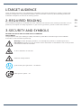
2-REQUIRED READING
The installation company is committed to read, understand and observe the assembly instructions and, in
particular, the chapter on safety regulations. If you have any questions, please contact Ideal Standard.
3-SECURITY AND SYMBOLS
MEANING OF SAFETY NOTICES AND SAFETY STANDARDS
SAFETY NOTES
The pictograms and signs relating to safety instructions, precautions and warnings in the installation
instructions have the following meaning:
Warning! Possible damaging situation, can damage the product or something around it.
Important! Instructions for use and other useful information to facilitate the use of the product
in accordance with the standards.
To test / attention to moisture.
Electrical voltage hazard.
System with hydro generator - Smartforce
Mains power system - AC
EN
RU
DE

4
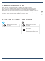
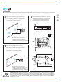
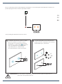
4-BEFORE INSTALLATION
Before starting the assembly, read thoroughly and understand the assembly instructions.
The product must be assembled, installed and connected only in accordance with these instructions.
Before applying your system confirm the compatibility of your installation at www.idealstandard.com.
When planning and installing sanitary equipment, local, national and international regulations and standards
must be observed and respected.
Examine the contents of the product before beginning the assembly to verify that it is complete.
A product that is incomplete or has visible damage or malfunctions should not be installed. No liability can be
assumed for damages caused by improper transport or by temporary storage.
5-ON-SITE ASSEMBLY CONDITIONS
Water grid pressure 0.5 bar at
max. 10 bar
Water grid pressure 0.5 bar at
max. 10 bar
Mains voltage
110 - 240 VAC / 50-60Hz with a
general switch for all poles
connected to mains supply and
contact opening capacity of 3 mm.
EN
RU
DE

5
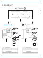
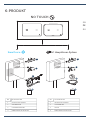
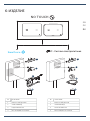
NR DESCRIPTION
1 CAPACITIVE SENSOR
2 SERVOMOTOR
3 HYDRO GENERATOR
4 ASSEMBLY INSTRUCTIONS
NR DESCRIPTION
1 CAPACITIVE SENSOR
2 SERVOMOTOR
3 TRANSFORMER
4 ASSEMBLY INSTRUCTIONS
6-PRODUCT
AC power-mains
Smartforce
1
2
3
4 4
3
2
1
NO TOUCH
EN
RU
DE

6
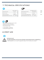
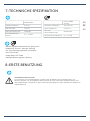
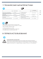
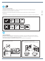
7-TECHNICAL SPECIFICATIONS
• Non-contact electronic flush system
• Capacitive Sensor Dual Flush
• For front flush plate installation
• IP68 protection rate
• Customizable LED lighting
• Configurable hygienic flush
8-FIRST USE
BEFORE ANY USE
For safety and longevity of the system, the battery of the hydro generator is only partially
charged. For optimum use, the full charge of the hydro generator, with the supplied charger,
is advised before any use (see Charging the Battery in the maintenance chapter).
SMARTFORCE
RATED VOLTAGE 6.4V DC
LiFePO₄
3000 mAh
0.5 - 10 BAR
BATTERY TYPE
BATTERY CAPACITY
OPERATION WATER PRESSURE
AC POWER-MAINS
OPERATION VOLTAGE 110-240V AC
50-60 HZ
BORNE KRE
0.5 - 10 BAR
GRID VOLTAGE
TYPE OF GRID CONNECTION
OPERATION WATER PRESSURE
EN
RU
DE

7
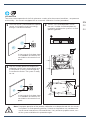
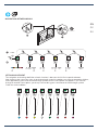
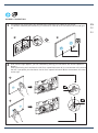
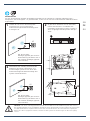
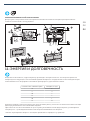
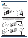
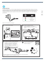
Once the sensor is connected to the power
source, it will confirm that it has energy
through 3 consecutive flashes.
After the standby period has elapsed, the
calibration routine starts automatically and
its completion is communicated again by
3 consecutive flashes. The system is ready
for use.
There is a 20-second period in which
the user / installer should complete the
installation and place the system in its final
operating position.
2
Note: For proper operation of the product, calibration must be performed with the sensor /
flush plate in its final operating position. Otherwise, the product may not detect the
user or cause incorrects or unwanted flushes. If any of these symptoms occur, turn
o the system and follow this procedure again.
1
3
X3
00.00 0:00:20.00
CALIBRATION
To ensure correct operation of the flush plate over a variety of environmental conditions - temperature
and humidity - the sensor is equipped with an automatic calibration function (procedure)
In the ceramic flush plate there
is no feedback (the flashes are
not visible in the ceramic flush
plate).
In the ceramic flush plate there
is no feedback (the flashes are
not visible in the ceramic flush
plate).
a
CLICK
b
X3
EN
RU
DE

8
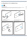
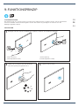
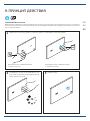
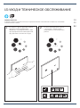
9-PRINCIPLE OF OPERATION
SYSTEM ACTUATION
The realization of no touch flushes is achieved through an electronic system, composed of capacitive
sensors, that senses user inputs. Detection is made up to 30mm from the flush plate.
INTERACTION
1
2
Move your hand close to the flush symbol you want to perform
Remain until the LED lights up or the flush
is performed Remove your hand
Lower volume flush (half-flush)
(left capacitive button)
Higher volume flush (full flush):
(right capacitive button)
0:00:01.00
3
EN
RU
DE

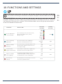
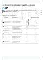
10-FUNCTIONS AND SETTINGS
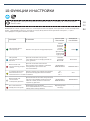
FUNCTION DESCRIPTION AVAILABLE
SETTINGS
FACTORY
SETTINGS
Colour adjustment
of the LED lights
The following colours can be set: Blue,
Red, Yellow, White, Green, Violet,
Orange, Purple
Blue
Red
Yellow
White
Green
Violet
Orange
Purple
Blue
Sensor sensitivity
adjustment
The sensor allows you to adjust the
detection sensitivity in three levels
Low
Medium
High
High
Enable or disable
duty flush
The sensor allows automatic flushs to be
performed at regular intervals if there is
no frequent usage
ON
OFF OFF
Set automatic/
hygienic flush timing
It is possible to define three regular time
intervals between automatic flushes
3H
24H
72H
24H
Enable or disable
sensor lighting
For greater energy savings (or if the
ceramic flush plate is used), it is possible
to deactivate the sensor illumination
ON
OFF ON
Reset factory
settings
The parameters for all functions are reset
to the factory default values Reset -
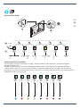
MENU NAVIGATION
Navigation through the 6 menus is done using the physical button on the back of the sensor. To activate
the menu, press the button for 5 seconds. The illumination of both sensors will light up and the colour
of the LEDs indicates the active menu.
For functions and settings in the ceramic flush plate, see page 12 to disassemble the flush plate.
EN
RU
DE
9

10
EN
RU
DE
SETTINGS AJUSTMENT
The navigation and settings definition of each function is done on the full flush capacitive button.
After choosing the menu you want, to go through each one of the options you have to proceed as follows,
when approaching your hand to the discharge symbol the first menu option will appear. If you want to
change to another menu option, you always have to bring your hand closer to the discharge symbol.
Check the scheme below:
NAVIGATION BETWEEN MENUS
Low Medium High 3H 24H 72HON OFF ON OFF
START
0:00:05.00
a
b
RESET
a
b

11
EN
RU
DE
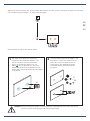
1With each change made, the flush plate/
sensor reports the new setting status
through the number of flashes (e.g. in
menu , the indication that the high
sensitivity level has been selected is given
by 3 consecutive blue flashes).
To validate your changes and exit the
menu, wait 10 seconds without interacting
with the sensor. The flush plate is ready for
use when the lights go o.
2
Note: All settings are stored in the sensor memory even when the sensor is out of power or
is restarted.
After setting the desired menu option, wait, and the system will take your option and return to discharge
mode. As you can verify below:
These procedures are the same for all menus.
0:00:10.00
X3

12
EN
RU
DE
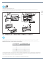
When the cistern is being filled - when water flows from the angle valve to the filler mechanism - the hydro
generator generates an electric current. This energy is stored in the battery for later use. In turn, this battery
feeds the capacitive sensor for the user interface and actuator mechanism to perform flushes.
The high-capacity battery pack ensures system operation for several months, even with reduced product
usage.
With more frequent use, their lifetime is extended, thanks to the energy generated by the hydro generator - the
surplus energy generated is accumulated in the batteries.
*It is possible to recharge the batteries through the provided charger.
FLUSHES PER DAY CHARGES (2 YEARS)
0 5
5 4
10 3
15 2
20 1
25 0
11-ENERGY AND SUSTAINABILITY
DISASSEMBLY OF CERAMIC FLUSH PLATE
To access the menu settings on the ceramic flush plate it is necessary to disassemble the flush plate as
instructed.
UNLOCK
UNLOCK
CRACK
-
+-
a
b
c
d
e

13
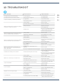
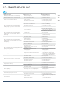
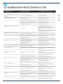
12-TROUBLESHOOT
MALFUNCTION POSSIBLE CAUSE PROCEDIMENTO
Flush plate flashes red after flushing • Low energy level • Recharge battery
Flush plate flashes red and doesn’t flush • Extremely low energy level • Recharge battery
Frequent low battery (red flashes) indication • Clogged filter • Verify/clean the filter
• Faulty hydro generator • Replace hydro generator
When interacting with the flush plate, lighting
works but no flush is performed
• Faulty software • Reboot system
• Servomotor misconnection • Check connections
• Faulty servomotor • Replace servomotor
• Empty cistern
• Check angle valve
• Check for eventual blocking in the
filling mechanism (inlet valve)
• Check for water in the grid
When interacting with the flush plate, lighting
doesn’t work but a flush is performed
• Faulty software • Reboot system
• LED function deactivated • Check LED function setting
When interacting with the flush plate, lighting
doesn’t work and no flush is performed
• Faulty software • Restart system
• Drained battery • Recharge battery
• Misconnections • Check connection with hydro
generator
• Faulty hydro generator • Replace hydrogenate
• Poor calibration • Reboot system
• Faulty sensor • Replace sensor / flush plate
When interacting with the flush plate, two
flashes in both sensors are presented and no
flush is performed
• Cleaning mode activated due to poor
calibration • Reboot system
• Excessive condensation inside the flush plate • Verify / clean flush plate interior
• Flush volumes may be set incorrectly
• Check the flush mechanism (outlet
valve) configuration
• Check if the filling mechanism (inlet
valve) is performing correctly
Water runs continuously in ceramic bowl
Ceramic bowl cleaning is not eective
• Faulty software • Reboot system
• Faulty rubber sealing • Replace rubber sealing
• Faulty flush system • Replace flush system
• Faulty filling mechanism (inlet valve) • Replace filling mechanism (inlet valve)
Unprovoked flushes • Hygienic automatic flush activated • Verify hygienic automatic flush
function setting
• Poor calibration • Reboot system
Incorrect flushes
• Faulty software • Reboot system
• Dirty or wet flush plate • Verify / clean flush plate interior
• Poor calibration • Reboot system
Charger doesn’t show green light • Faulty wall charger • Replace the wall charger
• Faulty hydro generator • Replace hydro generator
Long filling times
• Clogged filter • Verify/clear hydro generator filter
• Low water grid pressure (<2 bar/>120s) • Remove flow regulator from the
filling mechanism (inlet valve)
EN
RU
DE

14
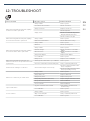
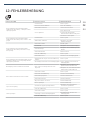
12-TROUBLESHOOT
MALFUNCTION POSSIBLE CAUSE PROCEDIMENTO
When interacting with the flush plate, lighting
works but no flush is performed
• Faulty software • Reboot system
• Servomotor misconnection • Check connections
• Faulty servomotor • Replace servomotor
• Empty cistern
• Check angle valve
• Check for eventual blockage in the
filling mechanism (inlet valve)
• Check for water in the grid
When interacting with the flush plate, lighting
doesn’t work but a flush is performed
• Faulty software • Reboot system
• LED function deactivated • Check LED function setting
When interacting with the flush plate, lighting
doesn’t work and no flush is performed
• Faulty software • Reboot system
• Blackout • Check electrical power
• Faulty software • Reboot system
• Falha de energia • Check connections to the mains
adaptor
• Misconnections • Check connections to the mains
adaptor
• Faulty mains adaptor • Replace mains adaptor
• Poor calibration • Reboot system
• Faulty sensor • Replace sensor / flush plate
When interacting with the flush plate, two
flashes in both sensors are present and no flush
is performed
• Cleaning mode activated due to poor calibration • Reboot system
• Excessive condensation inside the flush plate • Verify / clean flush plate interior
• Flush volumes may be set incorrectly
• Check the flush mechanism (outlet
valve) configuration
• Check if the filling mechanism (inlet
valve) is performing correctly
Water runs continuously in ceramic bowl
• Faulty software • Reboot system
• Faulty rubber seal • Replace rubber seal
• Faulty flush system • Replace flush system
• Faulty filling mechanism (inlet valve) • Replace filling mechanism (inlet valve)
Unprovoked flushes • Hygienic automatic flush activated • Verify hygienic automatic flush
function setting
• Poor calibration • Reboot system
Incorrect flushes
• Faulty software • Reboot system
• Dirty or wet flush plate • Verify / clean flush plate interior
• Poor calibration • Reboot system
Ceramic bowl cleaning is not eective
• Desynchronized servomotor • Manual calibration
• Incorrect flushes • Manual calibration
EN
RU
DE

15
2
1
MANUAL CALIBRATION
To calibrate the servomotor you need to press the button at the back of the sensor.
The button should be pressed during 30 seconds or more (a) until the two blue flushes (b) light
up.
After the blue light appears, you can calibrate by placing your hand over one of the capacitive
buttons.
When positioning the hand over the half flush capacitive button (a), the servomotor will move to
the left. If you place your hand over the full flush capacitive button (b) the servomotor will move
to the right.
> 0:00:30.00
ZOOCK!!
0º
CHECK
a b
a
b
EN
RU
DE

16
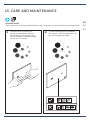
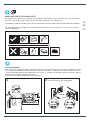
13-CARE AND MAINTENANCE
CLEANING MODE
The flush plate has a cleaning mode that allows the user to clean it without provoking undesired flushes.
Unlike the other functions, this
can be activated directly without
disassembling the flush plate, with
the simultaneous interaction of both
sensors for 10 seconds.
Once the cleaning time has elapsed -
60 seconds - the flush plate returns to
the normal operating mode.
21
0:00:10.00 0:00:60.00
EN
RU
DE

17
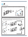
CLEANING THE FLUSH PLATE
The surface is simple to clean and care for. Use a soft cloth and soap and water solution for regular care.
Wipe clean with a dry cloth.
Avoid the use of abrasives or solvents, which damage the surface.
Damage caused by improper handling by the user is not covered by our warranty.
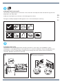
CLEANING THE FILTER
For protection of the hydro generator and filling mechanism (inlet valve), the Hydroboost system
incorporates a small particles filter in the water circuit. In case of installation in areas with polluted water/
new buildings, there is the possibility of debris accumulating over time and loss of circuit eciency.
Therefore, periodic maintenance is advised.
Open the flush plate.
1Disconnect all electrical connections and
remove counterplate.
2
CRACK
ab
EN
RU
DE

18
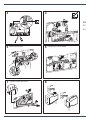
Close the stop valve
3
Retirar servomotor
5
Remove hydro generator
7Wash thoroughly with water on both sides.
8
Disconnect the flexible hose
4
19
Remove the central block
6
a
b
a
b
c’
c”
b
a
a
b
EN
RU
DE

19
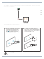
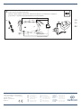
CHARGING THE BATTERY
The Smartforce system consists of a hydro generator and a battery pack. As such, the energy level in
the batteries might be low with infrequent use (the hydro generator only produces energy and
charges the battery when flushes are performed) and / or by the natural decay of the batteries over time.
In both cases, the system may need to be charged with the charger provided for this purpose.
Charging
Fully charged
To do this, follow the procedure:
Remove the flush plate.
1Remove the hydro generator charging cable
from its housing. Remove the safety cap
from the end of the cable and connect to
the end of the charger wire
2
3
CRACK
The system will be fully charged when the charger light turns green.
Charging time should be less than 4 hours.
The system can be used
normally during charging
Connect the charger to a wall outlet and
confirm that the charger light (red) lights up,
indicating that it is being charged
4:00:00.00
a
b
a
b
EN
RU
DE

20
Once completed, the safety cap should be placed back on the end of the cable and
the cable should be housed on the counter plate.
The flush plate should be placed back into its operating position and the charger
stored for future use.
4
a
c
CLICK
b
EN
RU
DE
Seite wird geladen ...
Seite wird geladen ...
Seite wird geladen ...
Seite wird geladen ...
Seite wird geladen ...
Seite wird geladen ...
Seite wird geladen ...
Seite wird geladen ...
Seite wird geladen ...
Seite wird geladen ...
Seite wird geladen ...
Seite wird geladen ...
Seite wird geladen ...
Seite wird geladen ...
Seite wird geladen ...
Seite wird geladen ...
Seite wird geladen ...
Seite wird geladen ...
Seite wird geladen ...
Seite wird geladen ...
Seite wird geladen ...
Seite wird geladen ...
Seite wird geladen ...
Seite wird geladen ...
Seite wird geladen ...
Seite wird geladen ...
Seite wird geladen ...
Seite wird geladen ...
Seite wird geladen ...
Seite wird geladen ...
Seite wird geladen ...
Seite wird geladen ...
Seite wird geladen ...
Seite wird geladen ...
Seite wird geladen ...
Seite wird geladen ...
-
 1
1
-
 2
2
-
 3
3
-
 4
4
-
 5
5
-
 6
6
-
 7
7
-
 8
8
-
 9
9
-
 10
10
-
 11
11
-
 12
12
-
 13
13
-
 14
14
-
 15
15
-
 16
16
-
 17
17
-
 18
18
-
 19
19
-
 20
20
-
 21
21
-
 22
22
-
 23
23
-
 24
24
-
 25
25
-
 26
26
-
 27
27
-
 28
28
-
 29
29
-
 30
30
-
 31
31
-
 32
32
-
 33
33
-
 34
34
-
 35
35
-
 36
36
-
 37
37
-
 38
38
-
 39
39
-
 40
40
-
 41
41
-
 42
42
-
 43
43
-
 44
44
-
 45
45
-
 46
46
-
 47
47
-
 48
48
-
 49
49
-
 50
50
-
 51
51
-
 52
52
-
 53
53
-
 54
54
-
 55
55
-
 56
56


IDEAL STANDARD R0129 Installationsanleitung
- Typ
- Installationsanleitung
- Dieses Handbuch eignet sich auch für
in anderen Sprachen
Andere Dokumente
-
GROHE Tectron Technical Instructions
-
-
Duravit WD5006 Bedienungsanleitung
-
-
-
 Tecma Evolution Operation and Installation Manual
-
Iqua S10 Installation & User Manual
-
BWT AQA Perla Installationsanleitung
-
Dometic SO5148 Benutzerhandbuch
