E-flite EFL15250 Bedienungsanleitung
- Kategorie
- Ferngesteuertes Spielzeug
- Typ
- Bedienungsanleitung

Instruction Manual
Bedienungsanleitung
Manuel d’utilisation
Manuale di Istruzioni
SAFE
®
Select Technology, Optional Flight Envelope Protection
Turbo Timber 1.5m
®

EN
2
Turbo Timber 1.5m
As the user of this product, you are solely responsible for operating in a manner that does not endanger yourself and others or result in damage to the product or the property of others.
• Always keep a safe distance in all directions around your model to avoid
collisions or injury. This model is controlled by a radio signal subject to
interference from many sources outside your control. Interference can
cause momentary loss of control.
• Always operate your model in open spaces away from full-size vehicles,
traffi c and people.
• Always carefully follow the directions and warnings for this and any
optional support equipment (chargers, rechargeable battery packs, etc.).
• Always keep all chemicals, small parts and anything electrical out of the
reach of children.
• Always avoid water exposure to all equipment not specifi cally designed
and protected for this purpose. Moisture causes damage to electronics.
• Never place any portion of the model in your mouth as it could cause
serious injury or even death.
• Never operate your model with low transmitter batteries.
• Always keep aircraft in sight and under control.
• Always use fully charged batteries.
• Always keep transmitter powered on while aircraft is powered.
• Always remove batteries before disassembly.
• Always keep moving parts clean.
• Always keep parts dry.
• Always let parts cool after use before touching.
• Always remove batteries after use.
• Always ensure failsafe is properly set before fl ying.
• Never operate aircraft with damaged wiring.
• Never touch moving parts.
NOTICE
All instructions, warranties and other collateral documents are subject to change at the sole discretion of Horizon Hobby, LLC. For up-to-date product
literature, visit www.horizonhobby.com or www.towerhobbies.com and click on the support or resources tab for this product.
Meaning of Special Language:
The following terms are used throughout the product literature to indicate various levels of potential harm when operating this product:
WARNING: Procedures, which if not properly followed, create the probability of property damage, collateral damage, and serious injury OR create a high
probability of superfi cial injury.
CAUTION: Procedures, which if not properly followed, create the probability of physical property damage AND a possibility of serious injury.
NOTICE: Procedures, which if not properly followed, create a possibility of physical property damage AND little or no possibility of injury.
WARNING: Read the ENTIRE instruction manual to become familiar with the features of the product before operating. Failure to operate the product
correctly can result in damage to the product, personal property and cause serious injury.
This is a sophisticated hobby product. It must be operated with caution and common sense and requires some basic mechanical ability. Failure to operate this
Product in a safe and responsible manner could result in injury or damage to the product or other property. This product is not intended for use by children
without direct adult supervision. Do not use with incompatible components or alter this product in any way outside of the instructions provided by Horizon
Hobby, LLC. This manual contains instructions for safety, operation and maintenance. It is essential to read and follow all the instructions and warnings in the
manual, prior to assembly, setup or use, in order to operate correctly and avoid damage or serious injury.
Safety Precautions and Warnings
14
+
AGE RECOMMENDATION:
Not for children under 14
years. This is not a toy.
WARNING AGAINST COUNTERFEIT PRODUCTS: If you ever need to replace your Spektrum receiver
found in a Horizon Hobby product, always purchase from Horizon Hobby, LLC or a Horizon Hobby
authorized dealer to ensure authentic high-quality Spektrum product. Horizon Hobby, LLC disclaims all support
and warranty with regards, but not limited to, compatibility and performance of counterfeit products or products
claiming compatibility with DSM or Spektrum technology.

EN
3
Box Contents
Quick Start Information
Transmitter
Setup
Set up your transmitter using the
transmitter setup chart
Dual Rates
Hi Rate Low Rate
Ail
33mm
33mm
25mm
25mm
Ele
22mm 16mm
Rud
30mm 20mm
Flaps
Full
=35mm
Half
=20mm
Center of Gravity
(CG)
60mm +/-5mm back from leading edge
of wing (without slats) at the fuselage.
Flight Timer
Setting
4 minutes
Table of Contents
54-60 oz
(1.53-1.7 Kg)
40.9 in (1040mm)
(61 in 1555mm)
Specifi cations
Motor: 10BL Brushless outrunner
800Kv (EFLM17552)
Installed Installed
ESC: 50 AMP Brushless ESC
(EFLA1050)
Installed Installed
Servo: 9 gram metal geared servo
(6 x SPMSA370)
Installed Installed
Receiver: Spektrum
™
AR636A
6-Channel Sport Receiver
(SMPAR636)
Installed
Required
to
Complete
Recommended Battery:
11.1V–14.8V 3S–4S 2200mAh
30C Li-Po (EFLB22003S30 or
EFLB22004S30*)
Required
to
Complete
Required
to
Complete
Recommended Battery Charger:
3 or 4-cell Li-Po battery balancing
charger
Required
to
Complete
Required
to
Complete
Recommended Transmitter:
Full-Range 6 channel 2.4GHz with
Spektrum DSMX
®
technology with
adjustable Dual Rates.
Required
to
Complete
Required
to
Complete
559.5 sq/in
(36.1 sq/dm)
SAFE
®
Select Technology (BNF Basic) .................................................................4
Prefl ight ..............................................................................................................4
Transmitter Setup (BNF Basic) .............................................................................4
Model Assembly .................................................................................................5
Binding / Switching ON and OFF SAFE Select (BNF Basic) ...................................8
Battery Installation and ESC Arming ....................................................................9
Control Horn and Servo Arm Settings ................................................................10
Center of Gravity (CG) ......................................................................................11
AS3X Control Direction Test (BNF Basic) ...........................................................11
In Flight Trimming (BNF Basic) ..........................................................................11
Flying Tips and Repairs .....................................................................................12
SAFE Select Flying ............................................................................................12
PNP Receiver Selection and Installation ............................................................13
Post Flight.........................................................................................................13
Motor Service ...................................................................................................13
Troubleshooting Guide AS3X .............................................................................13
Troubleshooting Guide ......................................................................................14
Float Installation (Optional) ................................................................................15
Flying Off Water ................................................................................................15
AMA National Model Aircraft Safety Code ..........................................................16
Limited Warranty ..............................................................................................17
Contact Information ..........................................................................................18
FCC Information ................................................................................................18
IC Information ...................................................................................................18
Compliance Information for the European Union ................................................18
Recommended Receivers .................................................................................66
Replacement Parts ............................................................................................67
Optional Parts ...................................................................................................68
To receive product updates, special offers and more,
register your product at https://www.horizonhobby.com/content/e-fl ite-rc
As of this printing, you may be required to register with the FAA
if you own this product.
For up-to-date information on how to register with the FAA,
please visit https://registermyuas.faa.gov/.
For additional assistance on regulations and guidance on UAS usage,
visit knowbeforeyoufl y.org/.
RECEIVER BIND INFORMATION
Channels
6
Frequency 2405 – 2476 MHz
Compatibility DSM2 and DSMX

EN
4
Turbo Timber 1.5m
Prefl ight
Transmitter Setup (BNF Basic)
IMPORTANT: After you set up your model, always rebind the transmitter and
receiver to set the desired failsafe positions.
Dual Rates
Take fi rst fl ights in Low Rate. For landings, use high rate elevator.
NOTICE: To ensure AS3X technology functions properly, do not lower rate
values below 50%. If lower rates are desired, manually adjust the position of
the pushrods on the servo arm.
NOTICE: If oscillation occurs at high speed, refer to the Troubleshooting
Guide for more information.
Expo
After fi rst fl ights, you may adjust expo in your transmitter.
†
Some of the terminology and function locations used in the iX12
programming may be slightly different than other Spektrum AirWare™
radios. The names given in parenthesis correspond to the iX12 programming
terminology. Consult your transmitter manual for specifi c information about
programming your transmitter.
* Flap programming values may vary slightly. For your initial fl ights use the
recommended fl ap travel settings provided in the Flaps section and adjust
the fl ap travel to your preference on subsequent fl ights.
Computerized Transmitter Setup
Start all transmitter programming with a blank ACRO model (perform a model
reset), then name the model.
Set Dual Rates to
HIGH 100%
LOW 70%
Set Servo Travel to 100%
Set Throttle Cut to -130%
DXe
Refer to spektrumrc.com for the appropriate download setup.
DX6i
1. Go to the SETUP LIST MENU
2. Set MODEL TYPE: ACRO
3. Go to ADJUST LIST MENU
4. Set FLAPS: Norm 100 Flap Elev 0
LAND -100 Flap Elev 30
DX7S
DX8
1. Go to the SYSTEM SETUP
2. Set MODEL TYPE: AIRPLANE
3. Set WING TYPE: 1 AIL 1 FLAP
4. Go to the FUNCTION LIST
5. Set FLAP SYSTEM: Choose Flap
NORM: 100% FLAP
MID: 0% FLAP 16% Elevator
LAND: -100% FLAP 30% Elevator
SPEED 2.0S: SWITCH = FLAP
DX6e
DX6 (Gen2)
DX7 (Gen2)
DX8e
DX8 (Gen2)
DX9
DX10t
DX18
DX20
iX12
1. Go to the SYSTEM SETUP
(Model Utilities)
†
2. Set MODEL TYPE: AIRPLANE
3. Set AIRCRAFT TYPE
(Model Setup, Aircraft Type)
†
:
WING: 1 AIL 1 FLAP
4. Go to the FUNCTION LIST
(Model Adjust)
†
5. Set FLAP SYSTEM:
SELECT SWITCH D:
POS 0: 100% FLAP*
POS 1: 0% FLAP* 16% Elevator
POS 2: -100% FLAP* 30% Elevator
SPEED 2.0
SAFE
®
Select Technology (BNF Basic)
1. Remove and inspect contents.
2. Read this instruction manual thoroughly.
3. Charge the fl ight battery.
4. Setup Transmitter using transmitter setup chart.
5. Fully assemble the airplane.
6. Install the fl ight battery in the aircraft (once it has been fully charged).
7. Check the Center of Gravity (CG).
8. Bind the aircraft to your transmitter.
9. Make sure linkages move freely.
10. Test the fl ap operation.
11. Perform the Control Direction Test with the transmitter.
12. Perform the AS3X Control Direction Test with the aircraft.
13. Adjust fl ight controls and transmitter.
14. Perform a radio system Range Test.
15. Find a safe open area to fl y.
16. Plan fl ight for fl ying fi eld conditions.
The BNF Basic version of this airplane includes SAFE Select technology which can offer an extra level of protection in fl ight. Use the following instructions to make
the SAFE Select system active and assign it to a switch. When enabled, SAFE Select prevents the airplane from banking or pitching past predetermined limits, and
automatic self-leveling keeps the airplane fl ying in a straight and level attitude when the aileron, elevator and rudder sticks are at neutral.
SAFE Select is enabled or disabled during the bind process. When the airplane is bound with SAFE Select enabled, a switch can be assigned to toggle between
SAFE Select mode and AS3X mode. AS3X
®
technology remains active with no banking limits or self leveling any time SAFE Select is disabled or OFF.
SAFE Select can be confi gured three ways;
• SAFE Select Off: Always in AS3X mode
• SAFE Select On- no switch assigned: Always in SAFE Select mode
• SAFE Select On with a switch assigned: Switch toggles between SAFE Select mode and AS3X mode

EN
Model Assembly
Landing Gear Installation
Mount the Landing Gear to the Fuselage
1. Insert one landing gear assembly into the pocket
on the side of the fuselage as shown. The landing
gear legs mount to the aluminum block which can pivot
in the pocket.
2. Thread the included 3 x 8mm machine screws
through the landing gear leg into the threaded
holes in the aluminum pivot block.
3. Repeat the process to install the second
landing gear assembly.
Mount the Spring Assemblies to the Fuselage
1. Align the spring assemblies with the mounting holes in the fuselage. These
assemblies mount to the plastic bracket pre-installed in the fuselage
between the landing gear.
2. Install the two 3 x 10mm self tapping screws to anchor the spring
assemblies in place.
Clamp the Spring Assemblies Together
1. Align the spring assemblies with the joiner bracket
2. Clamp the assembly together with the two 2 x 6mm self tapping screws.
3 x 10mm
self-tapping
button head
3 x 8mm
button head
machine
2 x 6mm
self-tapping
button head
5

EN
Model Assembly Continued
Horizontal Tail Installation
1. Slide the horizontal stabilizer joiner (A) into the hole in the rear of the fuselage.
2. Install the two piece (left and right) horizontal stabilizer as shown. Ensure the
control horn faces down.
3. Secure the horizontal stabilizer pieces in place using the two included 3 x 12 mm
self tapping screws (B).
4. Attach the pushrod keeper to the elevator control horn.
Pushrod keeper Installation
1. Insert the end of the pushrod with the 90˚ bend into the control horn and
insert the pushrod into the hole in the pushrod keeper.
2. Rotate the pushrod keeper and press into place on the pushrod until it
clicks into position.
B
A
1.
2.
3 x 12mm
self-tapping
button head
6
Turbo Timber 1.5m
Control Surface Centering
After assembly, transmitter setup and binding, confi rm that the control surfaces
are centered. If the control surfaces are not centered, mechanically center the
control surfaces before fl ying.
Set the trims and sub-trims to 0
1. If they are not centered, loosen the screw in the quick connector linkage on
the servo horn.
2. Slide the pushrod in the quick connector to change the length of the linkage
between the servo arm and the control horn so the control surface is centered.
3. Apply thread lock compound to the screw threads and tighten the screw to
secure the pushrod at the desired length.
90˚
90˚

EN
Model Assembly Continued
Wing Assembly
Slat Installation (Optional)
1. Carefully remove all the foam slat pocket covers (A) from the wing.
2. When the pocket is exposed, carefully apply medium CA to each slat pocket.
3. Mount the slat onto the wing with the rounded edge facing forward. Ensure
that the left and right slats are on the correct wing half. The slat and wing
halves are labeled with “L” and “R” indicators.
Wing Assembly
1. Insert the wing joiner tube and slide the left and right wing halves together, as shown.
2. Secure the wing together using the wing bracket (A).
3. Guide the Flaps, Lights and Aileron servo connectors (B) into the top of the
fuselage as shown.
Tip: If needed, use hemostats or pliers to pull the servo connectors into the fuselage.
4. Connect the Flaps, and Aileron connectors to respective
Y-harnesses connected to the receiver. The left and right servos
can be connected to either side of a Y-harness.
5. Connect the two light connectors (with exposed pins) to the light harness.
IMPORTANT: The ailerons must be connected to the receiver’s aileron port
(channel 2) with a Y-harness (included) for the AS3X
@
system to function properly.
6. Align the wing with the fuselage and secure into position using the included
2 nylon wing bolts (C).
CAUTION: DO NOT crush or otherwise damage the wiring when
attaching the wing to the fuselage.
Disassemble in reverse order.
Required Adhesives
Medium CA
A
A
C
emble
in
reverse
order.
B
Lights
Flaps
Ailerons
7

EN
8
Turbo Timber 1.5m
This product requires an approved Spektrum
™
DSM2
®
/DSMX
®
compatible
transmitter. Visit www.bindnfl y.com for a complete list of approved transmitters.
The aircraft has an optional SAFE Select feature, which can be switched ON or
OFF easily by binding in a specifi c manner as described below.
IMPORTANT: Before binding a transmitter, read the Transmitter Setup section of this
manual to ensure that your transmitter is properly programmed for this aircraft.
Transmitter and Receiver Binding / Enable or Disable SAFE Select (BNF)
Bind Plug Installation
BIND PLUG
Switching OFF SAFE Select Binding Sequence
Install Bind Plug
RX in Bind Mode
Bind TX to RX
Remove Bind Plug
Install Bind Plug
Remove Bind Plug
RX in Bind Mode
Bind TX to RX
Binding Procedure / Switching OFF SAFE Select
IMPORTANT: The included AR636 receiver has been programmed for
operation specifi cally for this aircraft. Refer to the receiver manual for
correct setup if the receiver is replaced or is used in another aircraft.
CAUTION: When using a Futaba
®
transmitter with a Spektrum DSM
module, you must reverse the throttle channel and rebind. Refer to your
Spektrum module manual for binding and failsafe instructions. Refer to your
Futaba transmitter manual for instructions on reversing the throttle channel.
1. Move the transmitter controls to neutral (fl ight controls: rudder, elevators
and ailerons) or to low positions (throttle, throttle trim). *
2. Install a bind plug in the receiver bind port.
3. Place the aircraft level on its wheels, then connect the fl ight battery to
the ESC.
The motor will produce a series of sounds.
The orange bind LED on the receiver will begin to fl ash rapidly. DO
NOT remove the bind plug at this time.
4. Take three steps away from the aircraft /receiver and then put the
transmitter in bind mode. Refer to your transmitter’s manual for specifi c
binding instructions.
IMPORTANT: Do not point the transmitter’s antenna directly at the
receiver while binding.
IMPORTANT: Keep away from large metal objects while binding.
5. The receiver is bound to the transmitter when the orange bind light on the
receiver stays orange. The ESC will produce a series of sounds. The tones
indicate the ESC is armed, provided the throttle stick and throttle trim are low
enough to trigger arming.
6. Remove the bind plug from the bind port.
IMPORTANT: Once bound, the receiver will retain its bind settings for that
transmitter until it has been intentionally changed, even when power is
cycled ON and OFF. Repeat the binding process as necessary.
SAFE Select OFF Indication
Every time the receiver is powered ON the surfaces will cycle back and forth
once to indicate that SAFE Select has been switched OFF.
The throttle will not arm if the transmitter’s throttle control is not put at the
lowest position. If problems are encountered, follow the binding instructions
and refer to the transmitter troubleshooting guide for other instructions. If
needed, contact the appropriate Horizon Product Support offi ce.
Binding Procedure / Switching ON SAFE Select
IMPORTANT: The included AR636 receiver has been programmed for
operation specifi cally for this aircraft. Refer to the receiver manual for
correct setup if the receiver is replaced or is used in another aircraft.
CAUTION: When using a Futaba
®
transmitter with a Spektrum DSM
®
module, you must reverse the throttle channel and rebind. Refer to your
Spektrum module manual for binding and failsafe instructions. Refer to your
Futaba transmitter manual for instructions on reversing the throttle channel.
1. Move the transmitter controls to neutral (fl ight controls: rudder, elevators
and ailerons) or to low positions (throttle, throttle trim).*
2. Install a bind plug in the receiver bind port.
3. Place the aircraft level on its wheels, then connect the fl ight battery to
the ESC. The motor will produce a series of sounds. The orange bind LED
on the receiver will begin to fl ash rapidly.
4. Remove the bind plug from the bind port.
5. Take three steps away from the aircraft /receiver and then put the
transmitter in bind mode. Refer to your transmitter’s manual for specifi c
binding instructions.
IMPORTANT: Do not point the transmitter’s antenna directly at the
receiver while binding.
IMPORTANT: Keep away from large metal objects while binding.
6. The receiver is bound to the transmitter when the orange bind light on the
receiver stays orange. The ESC will produce a series of sounds. The tones
indicate the ESC is armed, provided the throttle stick and throttle trim are low
enough to trigger arming.
IMPORTANT: Once bound, the receiver will retain its bind settings for that
transmitter until it has been intentionally changed, even when power is
cycled ON and OFF. Repeat the binding process as necessary.
SAFE Select ON Indication
Every time the receiver is powered ON the surfaces will cycle back and forth twice
with a slight pause at neutral position to indicate that SAFE Select is switched ON.
The throttle will not arm if the transmitter’s throttle control is not put at the
lowest position. If problems are encountered, follow the binding instructions
and refer to the transmitter troubleshooting guide for other instructions. If
needed, contact the appropriate Horizon Product Support offi ce.
Switching ON SAFE Select Binding Sequence
* Failsafe
If the receiver loses transmitter communication, the failsafe will activate. When activated, failsafe moves the throttle channel to its preset
failsafe position (low throttle) that was set during binding. All other channels move to actively level the aircraft in fl ight.

EN
9
Battery Installation and ESC Arming
Battery Selection
The E-fl ite
®
2200mAh 14.4V 4S 30C Li-Po battery (EFLM22004s30) is
recommended. The EFL22003S30 battery may also be used. Refer to the Optional
Parts List for other recommended batteries. If using a battery other than those
listed, the battery should be within the range of capacity, dimensions and weight of
the E-fl ite Li-Po battery packs to fi t in the fuselage. Be sure the model balances at
the recommended CG before fl ying.
1. Lower the throttle and throttle trim to the lowest settings. Power on the
transmitter, then wait 5 seconds.
2. For added security, apply the loop side (soft side) of the optional hook and
loop tape to the bottom of your battery, and the hook side to the battery tray.
3. Press the latch button and remove the battery hatch.
4. Install the fully charged battery in the center of the battery compartment as
shown. Secure using the hook and loop straps.
5. Connect the battery to the ESC (the ESC is now armed).
6. Keep the aircraft immobile and away from wind or the system will
not initialize.
• The ESC will sound a series of tones.
Three fl at tones followed immediately
by two ascending tones. The tones indicate the ESC is armed, provided the throttle
stick and throttle trim are low enough to trigger arming.
• An LED will light on the receiver when it is initialized
If the ESC sounds a continuous double beep after the fl ight battery is
connected, recharge or replace the battery.
7. Reinstall the battery hatch.
CAUTION: Always keep hands away from the propeller. When armed,
the motor will turn the propeller in response to any throttle movement.

EN
10
Turbo Timber 1.5m
Control Horn and Servo Arm Settings
The table to the right shows the factory settings for the control horns and servo
arms. Fly the aircraft at factory settings before making changes.
NOTICE: If control throws are changed from the factory settings, the AR636
gain values may need to be adjusted. Refer to the Spektrum AR636 manual
for adjustment of gain values.
After fl ying, you may choose to adjust the linkage positions for the desired
control response. See the table to the right.
Factory Setting Horns Arms
Elevator
Rudder
Aileron
Flaps
Tuning Horns Arms
More control throw
Less control throw
SAFE
®
Select Switch Designation
SAFE
®
Select technology can be assigned to any open switch (2 or 3 position) controlling
a channel (5–9) on your transmitter. Once assigned to a switch, SAFE select ON gives you
the fl exibility to choose SAFE technology or AS3X mode while in fl ight. If the aircraft is
bound with SAFE select OFF, the aircraft will be in AS3X mode exclusively.
IMPORTANT: Before assigning your desired switch, ensure that the travel for that
channel is set at 100% in both directions and the aileron, elevator, rudder and throttle
are all on high rate with the travel at 100%.
CAUTION: Keep all body parts well clear of the propeller and keep the aircraft
securely restrained in case of accidental throttle activation.
TIP: SAFE Select is assignable on any unused channels 5–9. See your transmitter
manual for more information about assigning a switch to a channel.
TIP: Use your radio channel monitor to confi rm that the four primary channels are
showing 100% travel while assigning the switch.
TIP: Use the channel monitor to make sure the switch you are assigning for SAFE
Select is active and driving a channel between 5-9 and that it is traveling 100% in each
direction.
TIP: Make sure your four primary channels are not reversed if you are having trouble
assigning a SAFE Select switch.
Assigning a switch
1. Bind the aircraft to choose SAFE Select ON. This will allow the system to be
assigned to a switch.
2. Hold both transmitter sticks to the inside bottom corners and toggle the desired
switch 5 times (1 toggle = full up and down) to assign that switch. The control
surfaces of the aircraft will move, indicating the switch has been selected.
Repeat the process to assign
a different switch or to
deactivate the current switch
if desired.
Mode 1 and 2 transmitters
X 5
100%
100%

EN
11
Center of Gravity (CG)
The CG location is measured from the leading edge of the wing at the root.
AS3X Control Direction Test (BNF Basic)
This test ensures that the AS3X
®
control system is functioning properly.
Assemble the aircraft and bind your transmitter to the receiver before
performing this test.
1. Raise the throttle just above 25%, then lower the throttle to
activate AS3X technology.
CAUTION: Keep all body parts, hair and loose clothing away from a
moving propeller, as these items could become entangled.
2. Move the entire aircraft as shown and ensure the control surfaces move in
the direction indicated in the graphic. If the control surfaces do not respond as
shown, do not fl y the aircraft. Refer to the receiver manual for more information.
Once the AS3X system is active, control surfaces may move rapidly. This is
normal. AS3X remains active until the battery is disconnected.
back from leading edge
of wing at the fuselage.
60 +/-5mm
During your fi rst fl ight, trim the aircraft for level fl ight at 1/2 throttle with fl aps
up. Make small trim adjustments with your transmitter’s trim switches to
straighten the aircraft’s fl ight path.
After adjusting the trim, do not touch the control sticks for 3 seconds. This
allows the receiver to learn the correct settings to optimize AS3X performance.
Failure to do so could affect fl ight performance.
In Flight Trimming (BNF Basic)
3 Seconds
Aircraft
movement
AS3X Reaction
ElevatorAileronRudder
(without slats installed)
• 60mm +/-5mm back from the leading edge
NOTICE: Install the battery but do not arm the ESC while checking the CG.
Personal injury may result.

EN
12
Turbo Timber 1.5m
Flying Tips and Repairs
Consult local laws and ordinances before choosing a fl ying location.
Getting Started
Before you fl y, range check the radio system. Refer to your specifi c transmitter
instruction manual for range test information. When you fi rst connect the battery to
the airplane AS3X will not be active. After advancing the throttle the fi rst time, the
AS3X system will be active and it is normal to see the control surfaces react to aircraft
movement. For your fi rst fl ights set your transmitter timer or a stopwatch to 3.5
minutes. Adjust your timer for longer or shorter fl ights once you have fl own the model.
Takeoff
Face the aircraft into the wind for takeoff. Set your transmitter to low rates and drop
the fl aps to takeoff position (half position). Flaps are not required, but lowering them
makes takeoffs shorter.
Gradually increase the throttle to full, and steer on the ground with rudder as necessary
to keep the aircraft rolling straight. Leave the elevator at neutral and allow the aircraft to
accelerate up to speed on the ground, then pull up gently on the elevator to rotate for takeoff.
When airborne, climb to a comfortable altitude, and then return the fl aps to the level position.
Flying
For your fi rst fl ights climb to a moderate altitude and get comfortable with the aircraft while
the battery is fresh. Get a feel for the aircraft’s low speed performance with the fl aps up
and down at a safe altitude (approximately 100 feet or more) before being required to make
your fi rst landing attempt. Land the aircraft when the timer expires. If at any time the motor
power reduces, land the aircraft immediately to recharge the fl ight battery. See the Low
Voltage Cutoff (LVC) section for more details on maximizing battery health and run time.
Landing
Plan to land the aircraft into the wind when possible. Fly downwind and turn
into the wind to begin the approach. Lower the throttle and lower the fl aps to
the landing position (full down position.) Flaps will make the landing approach
steeper and slower, and allow for a smoother landing. If there is a signifi cant
crosswind, only lower the fl aps to the takeoff position (middle position) which
will help maintain speed and better directional control during approach.
During the approach and descent, keep the wings level and the aircraft pointed into the
wind. The angle of attack (the angle between the aircraft’s pitch attitude and the horizon)
should remain consistent and slightly nose high during the decent. With the angle of attack
maintained during the descent, the speed and descent rate is mostly controlled with small
throttle changes. Stay into the throttle to maintain speed and control during decent until the
aircraft is ready to fl are. As the airplane descends into ground effect, fully lower the throttle,
pull the nose up more to bleed off airspeed (fl are), and the aircraft will settle on its wheels.
If landing on grass, it is best to hold full up elevator after touchdown and when
taxiing to prevent a nose over. Once on the ground, avoid sharp turns until the
plane has slowed enough to prevent scraping the wingtips.
NOTICE: If a crash is imminent, reduce the throttle and trim fully. Failure to do so
could result in extra damage to the airframe, as well as damage to the ESC and
motor.
NOTICE: After any impact, always ensure the receiver is secure in the
fuselage. If you replace the receiver, install the new receiver in the same
orientation as the original receiver or damage may result.
NOTICE: Crash damage is not covered under warranty.
NOTICE: When you are fi nished fl ying, never leave the aircraft in direct sunlight
or in a hot, enclosed area such as a car. Doing so can damage the aircraft.
Low Voltage Cutoff (LVC)
When a Li-Po battery is discharged below 3V per cell, it will not hold a charge.
The ESC protects the fl ight battery from over-discharge using Low Voltage
Cutoff (LVC). Before the battery charge decreases too much, LVC removes
power supplied to the motor. Power to the motor reduces, showing that some
battery power is reserved for fl ight control and safe landing.
Disconnect and remove the Li-Po battery from the aircraft after use to prevent
trickle discharge. Charge your Li-Po battery to about half capacity before
storage. During storage, make sure the battery charge does not fall below 3V
per cell. LVC does not prevent the battery from over-discharge during storage.
NOTICE: Repeated fl ying to LVC will damage the battery.
Tip: Monitor your aircraft battery’s voltage before and after fl ying by using a
Li-Po Cell Voltage Checker (SPMXBC100, sold separately).
Oscillation
For most fl ight maneuvers the aircraft should fl y smoothly and normal, but it
is possible in some fl ight conditions you may see oscillation (the aircraft rocks
back and forth on one axis due to overcontrol). If oscillation occurs, refer to the
Troubleshooting Guide for more information.
Repairs
Thanks to the EPO foam material in this aircraft, repairs to the foam can be
made using virtually any adhesive (hot glue, regular CA, epoxy, etc). When parts
are not repairable, see the Replacement Parts List for ordering by item number.
For a listing of all replacement and optional parts, refer to the list at the end of
this manual.
NOTICE: Use of CA accelerant on your aircraft can damage paint. DO NOT
handle the aircraft until accelerant fully dries.
SAFE Select Flying Tips
When fl ying in SAFE Select mode the aircraft will return to level fl ight any time
the aileron and elevator controls are at neutral. Applying aileron or elevator
control will cause the airplane to bank, climb or dive, and the amount the stick
is moved will determine the attitude the airplane fl ies. Holding full control will
push the aircraft to the pre-determined bank and roll limits but it will not go
past those angles.
When fl ying with SAFE Select it is normal to hold the control stick defl ected with
moderate aileron input when fl ying through a turn. To fl y smoothly with SAFE Select
avoid making frequent control changes and don’t attempt to correct for minor
deviations. With SAFE Select, holding deliberate control inputs will command the
aircraft to fl y at a specifi c angle and the model will make all corrections to maintain
that fl ight attitude.
Return the elevator and aileron controls to neutral before switching from SAFE Select mode
to AS3X mode. If you do not neutralize controls when switching into AS3X mode, the control
inputs used for SAFE Select mode will be excessive for AS3X mode and the aircraft will
react immediately.
Differences between SAFE Select and AS3X modes
This section is generally accurate but does not take into account fl ight speed,
battery charge status, and many other limiting factors.
• In SAFE Select mode the aircraft will self level when the control stick is
neutralized.
In AS3X mode the aircraft will continue to fl y at its present attitude when the
control stick is neutralized.
• In SAFE Select mode holding a small amount of control will result in the model
banking or pitching to a moderate angle and remaining at that angle as long as
the control stick doesn’t move.
In AS3X mode holding a small amount of control will result in the model
continuing to pitch or roll at a slow rate as long as the control stick doesn’t
move.
• In SAFE Select mode holding full control will result in the airplane banking or
pitching to the predetermined limits and the aircraft will keep fl ying at that
attitude as long as the control stick is fully defl ected.
In AS3X mode holding full control will result in the aircraft pitching or rolling as
fast as possible, and it will continue to rapidly change attitude as long as the
control stick is fully defl ected.

EN
Motor Service
CAUTION: Always disconnect the fl ight battery before performing
motor service.
Disassembly
1. Remove the spinner screw and spinner from the propeller shaft.
2. Remove the spinner nut by using an adjustable wrench.
3. Remove the propeller, back hub and the propeller shaft from the motor shaft.
4. Remove the two screws from the sides of the cowling and remove
the cowling from the fuselage.
5. Remove the four screws and the motor with the X-mount from the fuselage.
6. Disconnect the motor wires from the ESC wires.
7. Remove the four 3 x 6mm Phillips head machine screws and motor from the X-mount.
Assembly
Assemble in reverse order.
• Correctly align and connect the motor wire colors with the ESC wires.
• Install the propeller with the paint facing out from the motor.
• Tighten the spinner nut to secure the propeller into place.
Wiring not shown
13
3 x 8mm
Phillips head
machine
2 x 10mm
Phillips head
self tapping
3 x 14mm
Phillips head
self tapping
Post Flight
1. Disconnect the fl ight battery from the ESC (Required for Safety and battery life).
2. Power OFF the transmitter.
3. Remove the fl ight battery from the aircraft.
4. Recharge the fl ight battery.
5. Repair or replace all damaged parts.
6. Store the fl ight battery apart from the aircraft and monitor the battery charge.
7. Make note of the fl ight conditions and fl ight plan results, planning for future fl ights.
Troubleshooting Guide AS3X
Problem Possible Cause Solution
Oscillation
Damaged propeller or spinner Replace propeller or spinner
Imbalanced propeller Balance the propeller
Motor vibration Replace parts or correctly align all parts and tighten fasteners as needed
Loose receiver Align and secure receiver in fuselage
Loose aircraft controls Tighten or otherwise secure parts (servo, arm, linkage, horn and control surface)
Worn parts Replace worn parts (especially propeller, spinner or servo)
Irregular servo movement Replace servo
Inconsistent fl ight
performance
Trim is not at neutral If you adjust trim more than 8 clicks, adjust the clevis to remove trim
Sub-Trim is not at neutral No Sub-Trim is allowed. Adjust the servo linkage
Aircraft was not kept immobile for 5
seconds after battery connection
With the throttle stick in lowest position. Disconnect battery, then reconnect battery and keep the
aircraft still for 5 seconds
Incorrect response
to the AS3X Control
Direction Test
Incorrect direction settings in the
receiver, which can cause a crash
DO NOT fl y. Correct the direction settings (refer to the receiver manual), then fl y
PNP Receiver Selection and Installation
The Spektrum AR636 receiver is recommended for ths airplane. If you choose
to install another receiver, ensure that it is at least a 5-channel full range
(sport) receiver. Refer to your receiver manual for correct installation and
operation instructions.
Installation (AR636 shown)
1. Remove the wing from the fuselage.
2. Mount the receiver parallel to the length of the fuselage as shown. Use
double-sided servo tape.
CAUTION: Incorrect installation of the receiver could cause a crash.
3. Attach the appropriate control surfaces to the their respective ports on the
receiver using the chart in the illustration.
AR636 Port
Assignments
BND/PRG = BIND
1 = Throttle
2 = Y-harness: Ailerons
3 = Elevator
4 = Rudder
5 = Lights
6 = Y-harness: Flaps

EN
14
Turbo Timber 1.5m
Problem Possible Cause Solution
Aircraft will not re-
spond to throttle but
responds to other
controls
Throttle not at idle and/or throttle trim too high Reset controls with throttle stick and throttle trim at lowest setting
Throttle servo travel is lower than 100% Make sure throttle servo travel is 100% or greater
Throttle channel is reversed Reverse throttle channel on transmitter
Motor disconnected from ESC Make sure motor is connected to the ESC
Extra propeller noise
or extra vibration
Damaged propeller and spinner, collet or motor Replace damaged parts
Propeller is out of balance Balance or replace propeller
Prop nut is too loose Tighten the prop nut
Reduced fl ight time
or aircraft under-
powered
Flight battery charge is low Completely recharge fl ight battery
Propeller installed backwards Install propeller with numbers facing forward
Flight battery damaged Replace fl ight battery and follow fl ight battery instructions
Flight conditions may be too cold Make sure battery is warm before use
Battery capacity too low for flight conditions Replace battery or use a larger capacity battery
Aircraft will not Bind
(during binding) to
transmitter
Transmitter too near aircraft during binding process
Move powered transmitter a few feet from aircraft, disconnect and reconnect
fl ight battery to aircraft
Aircraft or transmitter is too close to large metal
object, wireless source or another transmitter
Move aircraft and transmitter to another location and attempt binding again
The bind plug is not installed correctly in the bind port Install bind plug in bind port and bind the aircraft to the transmitter
Flight battery/transmitter battery charge is too low Replace/recharge batteries
Bind switch or button not held long enough during
bind process
Power off transmitter and repeat bind process. Hold transmitter bind
button or switch until receiver is bound
Aircraft will not
connect (after
binding) to
transmitter
Transmitter too near aircraft during connecting
process
Move powered transmitter a few feet from aircraft, disconnect and reconnect
fl ight battery to aircraft
Aircraft or transmitter is too close to large metal
object, wireless source or another transmitter
Move aircraft and transmitter to another location and attempt connecting again
Bind plug left installed in bind port Rebind transmitter to the aircraft and remove the bind plug before cycling power
Aircraft bound to different model memory
(ModelMatch
TM
radios only)
Select correct model memory on transmitter
Flight battery/Transmitter battery charge is too low Replace/recharge batteries
Transmitter may have been bound to a different air-
craft using different DSM protocol
Bind aircraft to transmitter
Control surface does
not move
Control surface, control horn, linkage or servo damage Replace or repair damaged parts and adjust controls
Wire damaged or connections loose Do a check of wires and connections, connect or replace as needed
Transmitter is not bound correctly or the incorrect
airplanes was selected
Re-bind or select correct airplanes in transmitter
Flight battery charge is low Fully recharge fl ight battery
BEC (Battery Elimination Circuit) of the ESC is
damaged
Replace ESC
Controls reversed Transmitter settings are reversed
Perform the Control Direction Test and adjust the controls on transmitter
appropriately
Motor power pulses
then motor loses
power
ESC uses default soft Low Voltage Cutoff (LVC) Recharge fl ight battery or replace battery that is no longer performing
Weather conditions might be too cold Postpone flight until weather is warmer
Battery is old, worn out, or damaged Replace battery
Battery C rating might be too small Use recommended battery
Troubleshooting Guide

EN
15
Flying off water poses a higher risk because piloting errors or water conditions
can cause the aircraft to become stranded. Only fl y from the water when a level
of comfort has been achieved fl ying the aircraft from the ground.
Pre-Flight
Ensure the optional fl oats are secure on the fuselage and the water rudders are correctly
connected and operating with the main rudder before putting the aircraft in the water.
Select an area to fl y that does not have water currents, salt water, or debris. Look around
the fl ight area and be aware of trees, docks, buoys, or other obstacles. Always fl y with a
spotter and avoid swimmers, boaters, people fi shing, and people on the beach.
Taxiing
When taxiing, use low throttle settings and the rudders to steer. Hold up
elevator to help keep the rudders in the water and the nose of the fl oats
above the surface. Steer into the wind when turning, and crab into the wind if
crosswind taxiing is required. When turning or crabbing into the wind, apply
aileron against the wind to keep the upwind side of the wing down and prevent
the aircraft from being fl ipped over. Do not apply down elevator when the
airplane is taxiing or during the takeoff run.
On Step
When speed increases with throttle, the fl oats will rise out of the water and begin
to plane on the surface of the water, riding “on step.” The fl oats will come on step
at a speed below fl ight speed, this is a transitional phase when the aircraft is not
up to fl ight speed yet. This is considered a high speed taxi. Do not attempt to take
off as soon as the aircraft comes on step. Use low to medium throttle and hold up
elevator to manage speed on the water during a high speed taxi.
Takeoff
To lift off from the water, set the fl aps to the takeoff position, hold up elevator and
accelerate the aircraft to bring it on step. Relax the up elevator as the airplane comes
on step and accelerate to fl ight speed with full throttle. When the aircraft is travelling
at a suffi cient speed, pull back slightly on the elevator to rotate for liftoff.
Landing
To land on the water, set the fl aps to the landing position, and fl y into the wind.
Reduce the throttle to a low setting but keep some power during the approach.
As the aircraft settles into ground effect, reduce the throttle fully and hold up
elevator to fl are. Hold up elevator through the touch down and as the airplane
decelerates on the water.
WARNING: Never attempt to retrieve a downed aircraft by swimming
unless you are suffi ciently trained and/or there is another person
available to respond in the case of an emergency.
CAUTION: Have a plan for retrieval in the event the airplane becomes
stranded. Never retrieve a downed model in the water alone.
CAUTION: If at any time water splashes in the fuselage while fl ying
from water, bring the airplane to shore, open the battery hatch and
immediately remove any water that may have gotten in the fuselage. Leave
the battery hatch open overnight to let the inside dry out and to prevent
moisture damage to the electronic components. Failure to do so could cause
the electronic components to fail, which could result in a crash.
TIP: Use a fi shing pole with heavy line as a retrieval tool. Attach a tennis ball to
the line, and throw the ball past a stranded aircraft to retrieve it.
Flying Off Water
Float Installation (Optional)
Float Assembly
1. Install the 2 cross members (A) to the left and right fl oats as shown.
2. Install the front and rear fl oat struts to the fl oats and secure the assembly
together using the included 4 fl oat plates (B) and 3mm x 25mm machine
screws (C). The front strut has slightly more of an angle than the rear strut
(Figure 1).
3. Install the front support members (D) as shown using the included self
tapping screws (E).
Float Assembly Installation
1. Align and mount the fl oat set assembly to the bottom of the fuselage.
2. Secure the back section of the fl oats to the fuselage using the included
bracket (F) and two 3mm x 10mm self tapping screws (G).
3. Secure the front section of the fl oats using the two included 3mm x 12mm
self tapping screws (H) to secure the front support members to the bottom
of the fuselage.
4. Attach the included wire from each fl oat rudder (I) to the pull–pull horn (J)
using the two included pins (K).
Disassemble in reverse order.
A
B
C
DE
F
G
H
I
J
Figure 1Fi
g
Front Strut
K

EN
16
Turbo Timber 1.5m
AMA National Model Aircraft Safety Code
Effective January 1, 2014
A. GENERAL
A model aircraft is a non-human-carrying aircraft capable of sustained fl ight
in the atmosphere. It may not exceed limitations of this code and is intended
exclusively for sport, recreation, education and/or competition. All model fl ights
must be conducted in accordance with this safety code and any additional
rules specifi c to the fl ying site.
1. Model aircraft will not be fl own:
(a) In a careless or reckless manner.
(b) At a location where model aircraft activities are prohibited.
2. Model aircraft pilots will:
(a) Yield the right of way to all man carrying aircraft.
(b) See and avoid all aircraft and a spotter must be used when appropriate.
(AMA Document #540-D.)
(c) Not fl y higher than approximately 400 feet above ground level within
three (3) miles of an airport, without notifying the airport operator.
(d) Not interfere with operations and traffi c patterns at any airport, heliport
or seaplane base except where there is a mixed use agreement.
(e) Not exceed a takeoff weight, including fuel, of 55 pounds unless in
compliance with the AMA Large Model Aircraft program. (AMA
Document 520-A.)
(f) Ensure the aircraft is identifi ed with the name and address or AMA
number of the owner on the inside or affi xed to the outside of the
model aircraft. (This does not apply to model aircraft fl own indoors).
(g) Not operate aircraft with metal-blade propellers or with gaseous boosts
except for helicopters operated under the provisions of AMA Document
#555.
(h) Not operate model aircraft while under the infl uence of alcohol or while
using any drug which could adversely affect the pilot’s ability to safely
control the model.
(i) Not operate model aircraft carrying pyrotechnic devices which explode
or burn, or any device which propels a projectile or drops any object
that creates a hazard to persons or property.
Exceptions:
• Free Flight fuses or devices that burn producing smoke and are
securely attached to the model aircraft during fl ight.
• Rocket motors (using solid propellant) up to a G-series size may
be used provided they remain attached to the model during fl ight.
Model rockets may be fl own in accordance with the National
Model Rocketry Safety Code but may not be launched from
model aircraft.
• Offi cially designated AMA Air Show Teams (AST) are authorized to
use devices and practices as defi ned within the Team AMA
Program Document (AMA Document #718).
(j) Not operate a turbine-powered aircraft, unless in compliance with the
AMA turbine regulations. (AMA Document #510-A).
3. Model aircraft will not be fl own in AMA sanctioned events, air shows or
model demonstrations unless:
(a) The aircraft, control system and pilot skills have successfully
demonstrated all maneuvers intended or anticipated prior to the
specifi c event.
(b) An inexperienced pilot is assisted by an experienced pilot.
4. When and where required by rule, helmets must be properly worn and
fastened. They must be OSHA, DOT, ANSI, SNELL or NOCSAE approved or
comply with comparable standards.
B. RADIO CONTROL
1. All pilots shall avoid fl ying directly over unprotected people, vessels,
vehicles or structures and shall avoid endangerment of life and property
of others.
2. A successful radio equipment ground-range check in accordance with
manufacturer’s recommendations will be completed before the fi rst fl ight
of a new or repaired model aircraft.
3. At all fl ying sites a safety line(s) must be established in front of which all
fl ying takes place (AMA Document #706.)
(a) Only personnel associated with fl ying the model aircraft are allowed at
or in front of the safety line.
(b) At air shows or demonstrations, a straight safety line must be
established.
(c) An area away from the safety line must be maintained for spectators.
(d) Intentional fl ying behind the safety line is prohibited.
4. RC model aircraft must use the radio-control frequencies currently allowed
by the Federal Communications Commission (FCC). Only individuals
properly licensed by the FCC are authorized to operate equipment on
Amateur Band frequencies.
5. RC model aircraft will not operate within three (3) miles of any pre-existing
fl ying site without a frequency-management agreement (AMA Documents
#922 and #923.)
6. With the exception of events fl own under offi cial AMA Competition
Regulations, excluding takeoff and landing, no powered model may be
fl own outdoors closer than 25 feet to any individual, except for the pilot
and the pilot’s helper(s) located at the fl ight line.
7. Under no circumstances may a pilot or other person touch a model aircraft
in fl ight while it is still under power, except to divert it from striking an
individual.
8. RC night fl ying requires a lighting system providing the pilot with a clear
view of the model’s attitude and orientation at all times. Hand-held illumi-
nation systems are inadequate for night fl ying operations.
9. The pilot of a RC model aircraft shall:
(a) Maintain control during the entire fl ight, maintaining visual contact
without enhancement other than by corrective lenses prescribed for
the pilot.
(b) Fly using the assistance of a camera or First-Person View (FPV) only
in accordance with the procedures outlined in AMA Document #550.
(C) Fly using the assistance of autopilot or stabilization system only in
accordance with the procedures outlined in AMA Document #560.
Please see your local or regional modeling association’s guidelines for proper, safe
operation of your model aircraft.

EN
17
Limited Warranty
What this Warranty Covers
Horizon Hobby, LLC, (Horizon) warrants to the original purchaser that the
product purchased (the “Product”) will be free from defects in materials and
workmanship at the date of purchase.
What is Not Covered
This warranty is not transferable and does not cover (i) cosmetic damage, (ii)
damage due to acts of God, accident, misuse, abuse, negligence, commercial
use, or due to improper use, installation, operation or maintenance, (iii)
modifi cation of or to any part of the Product, (iv) attempted service by anyone
other than a Horizon Hobby authorized service center, (v) Product not purchased
from an authorized Horizon dealer, or (vi) Product not compliant with applicable
technical regulations, or (vii) use that violates any applicable laws, rules, or
regulations.
OTHER THAN THE EXPRESS WARRANTY ABOVE, HORIZON MAKES NO OTHER
WARRANTY OR REPRESENTATION, AND HEREBY DISCLAIMS ANY AND ALL
IMPLIED WARRANTIES, INCLUDING, WITHOUT LIMITATION, THE IMPLIED
WARRANTIES OF NON-INFRINGEMENT, MERCHANTABILITY AND FITNESS
FOR A PARTICULAR PURPOSE. THE PURCHASER ACKNOWLEDGES THAT THEY
ALONE HAVE DETERMINED THAT THE PRODUCT WILL SUITABLY MEET THE
REQUIREMENTS OF THE PURCHASER’S INTENDED USE.
Purchaser’s Remedy
Horizon’s sole obligation and purchaser’s sole and exclusive remedy shall be
that Horizon will, at its option, either (i) service, or (ii) replace, any Product
determined by Horizon to be defective. Horizon reserves the right to inspect
any and all Product(s) involved in a warranty claim. Service or replacement
decisions are at the sole discretion of Horizon. Proof of purchase is required
for all warranty claims. SERVICE OR REPLACEMENT AS PROVIDED UNDER THIS
WARRANTY IS THE PURCHASER’S SOLE AND EXCLUSIVE REMEDY.
Limitation of Liability
HORIZON SHALL NOT BE LIABLE FOR SPECIAL, INDIRECT, INCIDENTAL
OR CONSEQUENTIAL DAMAGES, LOSS OF PROFITS OR PRODUCTION OR
COMMERCIAL LOSS IN ANY WAY, REGARDLESS OF WHETHER SUCH CLAIM IS
BASED IN CONTRACT, WARRANTY, TORT, NEGLIGENCE, STRICT LIABILITY OR
ANY OTHER THEORY OF LIABILITY, EVEN IF HORIZON HAS BEEN ADVISED OF
THE POSSIBILITY OF SUCH DAMAGES. Further, in no event shall the liability of
Horizon exceed the individual price of the Product on which liability is asserted.
As Horizon has no control over use, setup, fi nal assembly, modifi cation or
misuse, no liability shall be assumed nor accepted for any resulting damage
or injury. By the act of use, setup or assembly, the user accepts all resulting
liability. If you as the purchaser or user are not prepared to accept the liability
associated with the use of the Product, purchaser is advised to return the
Product immediately in new and unused condition to the place of purchase.
Law
These terms are governed by Illinois law (without regard to confl ict of law
principals). This warranty gives you specifi c legal rights, and you may also have
other rights which vary from state to state. Horizon reserves the right to change
or modify this warranty at any time without notice.
WARRANTY SERVICES
Questions, Assistance, and Services
Your local hobby store and/or place of purchase cannot provide warranty
support or service. Once assembly, setup or use of the Product has been
started, you must contact your local distributor or Horizon directly. This will
enable Horizon to better answer your questions and service you in the event
that you may need any assistance. For questions or assistance, please visit our
website at www.horizonhobby.com, submit a Product Support Inquiry, or call
the toll free telephone number referenced in the Warranty and Service Contact
Information section to speak with a Product Support representative.
Inspection or Services
If this Product needs to be inspected or serviced and is compliant in the country
you live and use the Product in, please use the Horizon Online Service Request
submission process found on our website or call Horizon to obtain a Return
Merchandise Authorization (RMA) number. Pack the Product securely using a
shipping carton. Please note that original boxes may be included, but are not
designed to withstand the rigors of shipping without additional protection. Ship
via a carrier that provides tracking and insurance for lost or damaged parcels,
as Horizon is not responsible for merchandise until it arrives and is accepted at
our facility. An Online Service Request is available at http://www.horizonhobby.
com/content/_service-center_render-service-center. If you do not have internet
access, please contact Horizon Product Support to obtain a RMA number along
with instructions for submitting your product for service. When calling Horizon,
you will be asked to provide your complete name, street address, email address
and phone number where you can be reached during business hours. When
sending product into Horizon, please include your RMA number, a list of the
included items, and a brief summary of the problem. A copy of your original
sales receipt must be included for warranty consideration. Be sure your name,
address, and RMA number are clearly written on the outside of the shipping
carton.
NOTICE: Do not ship LiPo batteries to Horizon. If you have any issue with a
LiPo battery, please contact the appropriate Horizon Product Support offi ce.
Warranty Requirements
For Warranty consideration, you must include your original sales receipt
verifying the proof-of-purchase date. Provided warranty conditions have
been met, your Product will be serviced or replaced free of charge. Service or
replacement decisions are at the sole discretion of Horizon.
Non-Warranty Service
Should your service not be covered by warranty, service will be completed
and payment will be required without notifi cation or estimate of the
expense unless the expense exceeds 50% of the retail purchase cost.
By submitting the item for service you are agreeing to payment of the service
without notifi cation. Service estimates are available upon request. You must
include this request with your item submitted for service. Non-warranty
service estimates will be billed a minimum of ½ hour of labor. In addition you
will be billed for return freight. Horizon accepts money orders and cashier’s
checks, as well as Visa, MasterCard, American Express, and Discover cards. By
submitting any item to Horizon for service, you are agreeing to Horizon’s Terms
and Conditions found on our website http://www.horizonhobby.com/content/_
service-center_render-service-center.
ATTENTION: Horizon service is limited to Product compliant in the country of
use and ownership. If received, a non-compliant Product will not be serviced.
Further, the sender will be responsible for arranging return shipment of the
un-serviced Product, through a carrier of the sender’s choice and at the
sender’s expense. Horizon will hold non-compliant Product for a period of 60
days from notifi cation, after which it will be discarded.
10/15
10/15
Contact Information
Country of Purchase Horizon Hobby Contact Information Address
United States
of America
Horizon Service Center
(Repairs and Repair Requests)
servicecenter.horizonhobby.com/
RequestForm/
2904 Research Rd
Champaign, Illinois, 61822 USA
Horizon Product Support
(Product Technical Assistance)
productsupport@horizonhobby.com
877-504-0233
Sales
websales@horizonhobby.com
800-338-4639
European Union
Horizon Technischer Service service@horizonhobby.eu
Hanskampring 9
D 22885 Barsbüttel, Germany
Sales: Horizon Hobby GmbH +49 (0) 4121 2655 100

EN
18
Turbo Timber 1.5m
FCC ID: BRWDASRX15
Contains IC: 6157A-AMRX15
FCC Information
This device complies with part 15 of the FCC rules. Operation is subject to the
following two conditions: (1) This device may not cause harmful interference,
and (2) this device must accept any interference received, including
interference that may cause undesired operation.
CAUTION: Changes or modifi cations not expressly approved by the party
responsible for compliance could void the user’s authority to operate the
equipment.
This product contains a radio transmitter with wireless technology which
has been tested and found to be compliant with the applicable regulations
governing a radio transmitter in the 2.400GHz to 2.4835GHz frequency range.
Supplier’s Declaration of Conformity
Turbo Timber 1.5m BNF Basic with AS3X and SAFE Select - EFL15250
Turbo Timber 1.5m PNP - EFL15275
This device complies with part 15 of the FCC Rules. Operation is subject
to the following two conditions: (1) This device may not cause harmful
interference, and (2) this device must accept any interference received,
including interference that may cause undesired operation.
CAUTION: Changes or modifi cations not expressly approved by the party
responsible for compliance could void the user’s authority to operate the
equipment.
NOTE: This equipment has been tested and found to comply with the limits
for a Class B digital device, pursuant to part 15 of the FCC Rules. These limits
are designed to provide reasonable protection against harmful interference
in a residential installation. This equipment generates, uses and can radiate
radio frequency energy and, if not installed and used in accordance with
the instructions, may cause harmful interference to radio communications.
However, there is no guarantee that interference will not occur in a particular
installation. If this equipment does cause harmful interference to radio or
television reception, which can be determined by turning the equipment off
and on, the user is encouraged to try to correct the interference by one or
more of the following measures:
• Reorient or relocate the receiving antenna.
• Increase the separation between the equipment and receiver.
• Connect the equipment into an outlet on a circuit different from that to
which the receiver is connected.
• Consult the dealer or an experienced radio/TV technician for help.
Horizon Hobby, LLC
2904 Research Rd.
Champaign, IL 61822
Email: compliance@horizonhobby.com
Web: HorizonHobby.com
FCC Information
IC Information
CAN ICES-3 (B)/NMB-3(B)
IC: 6157A-AMRX15
This device complies with Industry Canada licence-exempt RSS standard(s). Operation is subject to the following two conditions: (1) this device may not cause
interference, and (2) this device must accept any interference, including interference that may cause undesired operation of the device.
Compliance Information for the European Union
EU Compliance Statement:
EFL15275 Turbo Timber 1.5m PNP; Horizon Hobby, LLC hereby
declares that this product is in compliance with the essential
requirements and other relevant provisions of the EMC Directive.
EFL15250 Turbo Timber 1.5m BNF BASIC; Horizon Hobby, LLC hereby
declares that this product is in compliance with the essential requirements
and other relevant provisions of the RED and EMC Directives.
A copy of the EU Declaration of Conformity is available online at:
http://www.horizonhobby.com/content/support-render-compliance.
Instructions for disposal of WEEE by users in the European Union
This product must not be disposed of with other waste. Instead, it
is the user’s responsibility to dispose of their waste equipment by
handing it over to a designated collections point for the recycling
of waste electrical and electronic equipment. The separate
collection and recycling of your waste equipment at the time of
disposal will help to conserve natural resources and make sure
that it is recycled in a manner that protects human health and the
environment. For more information about where you can drop off
your waste equipment for recycling, please contact your local city
offi ce, your household waste disposal service or where you
purchased the product.

DE
19
Als Benutzer dieses Produkts sind ausschließlich Sie für den Betrieb auf eine Weise verantwortlich, die sie selbst oder andere nicht gefährdet, bzw. die zu keiner
Beschädigung des Produkts oder des Eigentums anderer führt.
• Halten Sie stets in allen Richtungen einen Sicherheitsabstand zu Ihrem Modell ein, um
Kollisionen und Verletzungen zu vermeiden. Dieses Modell wird über ein Funksignal
gesteuert. Funksignale können von außerhalb gestört werden, ohne dass Sie
darauf Einfl uss nehmen können. Dies kann zu einem vorübergehenden Verlust der
Steuerungskontrolle führen.
• Betreiben Sie Ihr Modell stets auf offenen Geländern, weit ab von Automobilen,
Verkehr und Menschen.
• Befolgen Sie die Anweisungen und Warnungen für dieses Produkt und jedwedes
optionales Zubehörteil (Ladegeräte, wiederaufl adbare Akkus etc.) stets sorgfältig.
• Halten Sie sämtliche Chemikalien, Kleinteile und elektrische Komponente stets außer
Reichweite von Kindern.
• Feuchtigkeit beschädigt die Elektronik. Vermeiden Sie den Wasserkontakt aller
Komponenten, die dafür nicht speziell ausgelegt und entsprechend geschützt sind.
• Nehmen Sie niemals ein Element des Modells in Ihren Mund, da dies zu schweren
Verletzungen oder sogar zum Tod führen könnte.
• Betreiben Sie Ihr Modell niemals mit schwachen Senderbatterien.
• Halten Sie das Fluggerät stets unter Blickkontakt und Kontrolle.
• Fliegen Sie nur mit vollständig aufgeladenen Akkus.
• Halten Sie den Sender stets eingeschaltet, wenn das Fluggerät eingeschaltet ist.
• Entfernen Sie stets den Akku, bevor Sie das Fluggerät auseinandernehmen.
• Halten Sie bewegliche Teile stets sauber.
• Halten Sie die Teile stets trocken.
• Lassen Sie die Teile stets auskühlen, bevor Sie sie berühren.
• Entfernen Sie nach dem Flug stets den Akku.
• Stellen Sie immer sicher, dass der Failsafe vor dem Flug ordnungsgemäß
eingestellt ist.
• Betreiben Sie das Fluggerät niemals bei beschädigter Verkabelung.
• Berühren Sie niemals sich bewegende Teile.
HINWEIS
Allen Anweisungen, Garantien und anderen zugehörigen Dokumenten sind Änderungen nach Ermessen von Horizon Hobby, LLC vorbehalten. Aktuelle
Produktliteratur fi nden Sie unter www.horizonhobby.com oder www.towerhobbies.com im Support-Abschnitt für das Produkt.
Begriffserklärung
Die folgende Begriffe werden in der gesamte Produktliteratur verwendet, um die Gefährdungsstufen im Umgang mit dem Produkt zu defi ieren:
WARNUNG: Verfahren können bei nicht ordnungsgemäßer Durchführung womöglich Schäden an Eigentum, Kollateralschäden UND schwere Verletzungen ODER
höchstwahrscheinlich oberfl ächliche Verletzungen verursachen.
ACHTUNG: Verfahren können bei nicht ordnungsgemäßer Durchführung womöglich Schäden an physischem Eigentum UND schwere
Verletzungen verursachen.
HINWEIS: Verfahren können bei nicht ordnungsgemäßer Durchführung womöglich Schäden an physischem Eigentum UND geringfügige oder keine Verletzungen verursachen.
WARNUNG: Lesen Sie die GESAMTE Bedienungsanleitung, um sich vor Inbetriebnahme mit den Funktionen des Produkts vertraut zu machen. Eine
nicht ordnungsgemäße Bedienung des Produkts kann das Produkt und persönliches Eigentum schädigen und schwere Verletzungen verursachen.
Dies ist ein hoch entwickeltes Produkt für den Hobbygebrauch. Es muss mit Vorsicht und Umsicht bedient werden und erfordert einige mechanische
Grundfertigkeiten. Wird das Produkt nicht sicher und umsichtig verwendet, so könnten Verletzungen oder Schäden am Produkt oder anderem Eigentum
entstehen. Dieses Produkt ist nicht für den Gebrauch durch Kinder ohne direkte Aufsicht eines Erwachsenen vorgesehen. Versuchen Sie nicht, das Produkt
ohne Zustimmung von Horizon Hobby, LLC zu zerlegen, mit nicht-kompatiblen Komponenten zu verwenden oder beliebig zu verbessern. Dieses Handbuch
enthält Sicherheitshinweise sowie Anleitungen zu Betrieb und Wartung. Es ist unerlässlich, dass Sie alle Anleitungen und Warnungen in diesem Handbuch vor
dem Zusammenbau, der Einrichtung oder der Inbetriebnahme lesen und diese befolgen, um eine korrekte Bedienung zu gewährleisten und Schäden bzw.
schwere Verletzungen zu vermeiden.
Sicherheitsmaßnahmen und Warnungen
14
+
Altersempfehlung: Nicht
für Kinder unter 14 Jahren.
Dies ist kein Spielzeug.
Warnung gegen gefälschte Produkte: Sollten Sie jemals einen Empfänger aus einem Horizon Hobby
Produkt wechseln wollen, kaufen Sie diesen bitte bei Horizon Hobby oder einem autorisierten Horizon Hobby
Händler um sicher zu stellen, dass Sie ein authentisches qualitativ hochwertiges Spektrum Produkt erhalten.
Horizon Hobby LLC lehnt jedwede Haftung, Garantie oder Unterstützung sowie Kompatibilitäts- oder
Leistungsansprüche zu DSM oder Spektrum in Zusammenhang mit gefälschten Produkten ab.

DE
INFORMATIONEN ZUM BINDEN DES EMPFÄNGERS
Kanäle 6
Frequenz 2405–2476MHz
Kompatibilität DSM2 und DSMX
20
Turbo Timber 1.5m
Lieferumfang
Schnellstartanleitung
Senderprogram-
mierung
Programmieren Sie den Sender mit diesen
Einstellungen:
Dual Rate
Hi Rate Low Rate
Querr.
33mm
33mm
25mm
25mm
Höhen-
ruder
22mm 16mm
Seiten-
ruder
30mm 20mm
Klappen
Voll
=35mm
Halb
=20mm
Schwerpunkt (CG) 60mm +/-5mm
von der Vorderkante
Timereinstellung-
Flugzeit
4 Minuten
Inhaltsverzeichnis
Komponenten
SAFE Select-Technologie .................................................................................. 21
Vor dem Flug .................................................................................................... 21
Sender Setup ................................................................................................... 21
Zusammenbau des Modells .............................................................................. 22
Montage des Modells; Fortsetzung ................................................................... 23
Binden/SAFE Select ein- und ausschalten (BNF Basic) ...................................... 25
Einsetzen des Akkus und armieren den Reglers ................................................ 26
Schalterbelegung von SAFE Select ................................................................... 27
Horn- und Servoarm-Einstellungen ................................................................... 27
Der Schwerpunkt (CG) ...................................................................................... 28
AS3X Kontrolltest .............................................................................................. 28
Trimmung im Flug ............................................................................................. 28
Flugtipps und Reparaturen ................................................................................ 29
Fliegen mit SAFE Select .................................................................................... 29
PNP Version Empfängerauswahl und Einbau ..................................................... 30
Motorwartung ................................................................................................... 30
Leitfaden zur Problemlösung AS3X .................................................................... 30
Leitfaden zur Problemlösung ............................................................................. 31
Montage des Modells; (Fortsetzung) ................................................................. 32
Starten von Gewässern ..................................................................................... 32
Haftungsbeschränkung .................................................................................... 33
Garantie und Service Kontaktinformationen....................................................... 34
Konformitätshinweise für die Europäische Union ............................................... 34
Empfohlene Empfänger ..................................................................................... 66
Ersatzteile ......................................................................................................... 67
Optionale Bauteile ............................................................................................. 68
Motoren: 10BL Brushless
Aussenläufer 800Kv (EFLM17552)
Eingebaut Eingebaut
ESC: 40 AMP Brushless ESC
(EFLA1040U)
Eingebaut Eingebaut
Servo: 9 gram
Metallgetriebeservos
(6 x
SPMSA370)
Eingebaut Eingebaut
Empfänger: Spektrum AR636A
6-Channel Sport Empfänger
(SMPAR636)
Eingebaut
Erford-
erlich
Empfohlener Akku: 11.1V
3S 2200mAh 30C Li-Po
(EFLB22003S30)
Erford-
erlich
Erford-
erlich
Empfohlenes Ladegerät:
3-zelliges LiPo-
Akkuausgleichsladegerät
Erford-
erlich
Erford-
erlich
Empfohlener Sender:
Spektrum AR636A 6-Channel
Sport Empfänger(SMPAR636)
Erford-
erlich
Erford-
erlich
Registrieren Sie sich unter https://www.horizonhobby.com/content/e-fl ite-rc
für Produktupdates, spezielle Angebote und mehr.
1.53-1.7 Kg
1040mm
1555mm
36.1 sq/dm
Seite wird geladen ...
Seite wird geladen ...
Seite wird geladen ...
Seite wird geladen ...
Seite wird geladen ...
Seite wird geladen ...
Seite wird geladen ...
Seite wird geladen ...
Seite wird geladen ...
Seite wird geladen ...
Seite wird geladen ...
Seite wird geladen ...
Seite wird geladen ...
Seite wird geladen ...
Seite wird geladen ...
Seite wird geladen ...
Seite wird geladen ...
Seite wird geladen ...
Seite wird geladen ...
Seite wird geladen ...
Seite wird geladen ...
Seite wird geladen ...
Seite wird geladen ...
Seite wird geladen ...
Seite wird geladen ...
Seite wird geladen ...
Seite wird geladen ...
Seite wird geladen ...
Seite wird geladen ...
Seite wird geladen ...
Seite wird geladen ...
Seite wird geladen ...
Seite wird geladen ...
Seite wird geladen ...
Seite wird geladen ...
Seite wird geladen ...
Seite wird geladen ...
Seite wird geladen ...
Seite wird geladen ...
Seite wird geladen ...
Seite wird geladen ...
Seite wird geladen ...
Seite wird geladen ...
Seite wird geladen ...
Seite wird geladen ...
Seite wird geladen ...
Seite wird geladen ...
Seite wird geladen ...
Seite wird geladen ...
Seite wird geladen ...
Seite wird geladen ...
Seite wird geladen ...
-
 1
1
-
 2
2
-
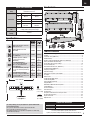 3
3
-
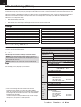 4
4
-
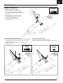 5
5
-
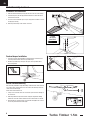 6
6
-
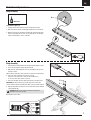 7
7
-
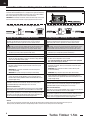 8
8
-
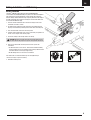 9
9
-
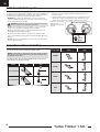 10
10
-
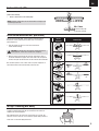 11
11
-
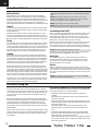 12
12
-
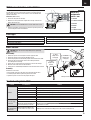 13
13
-
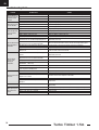 14
14
-
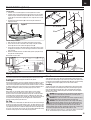 15
15
-
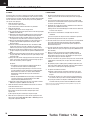 16
16
-
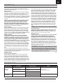 17
17
-
 18
18
-
 19
19
-
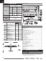 20
20
-
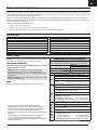 21
21
-
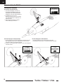 22
22
-
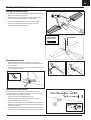 23
23
-
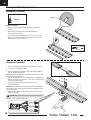 24
24
-
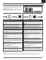 25
25
-
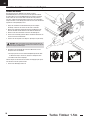 26
26
-
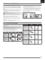 27
27
-
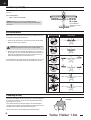 28
28
-
 29
29
-
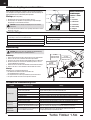 30
30
-
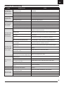 31
31
-
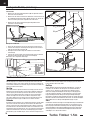 32
32
-
 33
33
-
 34
34
-
 35
35
-
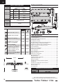 36
36
-
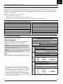 37
37
-
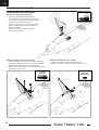 38
38
-
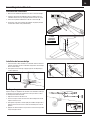 39
39
-
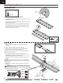 40
40
-
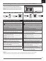 41
41
-
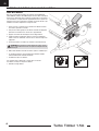 42
42
-
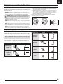 43
43
-
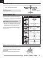 44
44
-
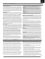 45
45
-
 46
46
-
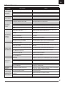 47
47
-
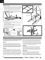 48
48
-
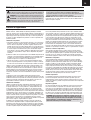 49
49
-
 50
50
-
 51
51
-
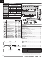 52
52
-
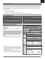 53
53
-
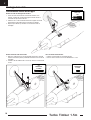 54
54
-
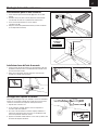 55
55
-
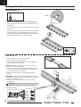 56
56
-
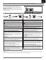 57
57
-
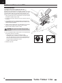 58
58
-
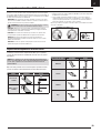 59
59
-
 60
60
-
 61
61
-
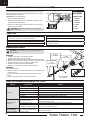 62
62
-
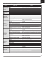 63
63
-
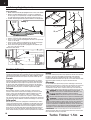 64
64
-
 65
65
-
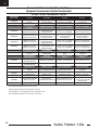 66
66
-
 67
67
-
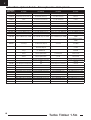 68
68
-
 69
69
-
 70
70
-
 71
71
-
 72
72


E-flite EFL15250 Bedienungsanleitung
- Kategorie
- Ferngesteuertes Spielzeug
- Typ
- Bedienungsanleitung
in anderen Sprachen
- English: E-flite EFL15250 Owner's manual
- français: E-flite EFL15250 Le manuel du propriétaire
- italiano: E-flite EFL15250 Manuale del proprietario
Verwandte Artikel
-
E-flite EFLAS6410NBLT Bedienungsanleitung
-
E-flite Carbon-Z Cub Benutzerhandbuch
-
-
-
-
E-flite EFL011500 Bedienungsanleitung
-
-
-
-
Andere Dokumente
-
Horizon Hobby UMX YAK 54 3D Benutzerhandbuch
-
ParkZone PKZU1152 Bedienungsanleitung
-
HobbyZone HBZ5700 Bedienungsanleitung
-
-
FMS 1220mm Super EZ V4 Bedienungsanleitung
-
-
Spektrum TX/RX USB Programming Cable Bedienungsanleitung
-
-
-