Malaguti F18 WARRIOR Electric System Troubleshooting
- Kategorie
- Kabelnetzwerktester
- Typ
- Electric System Troubleshooting

MALAGUTI F18MALAGUTI F18
MALAGUTI F18MALAGUTI F18
MALAGUTI F18
IDENTIFICAZIONE GUASTI IMPIANTO ELETTRICOIDENTIFICAZIONE GUASTI IMPIANTO ELETTRICO
IDENTIFICAZIONE GUASTI IMPIANTO ELETTRICOIDENTIFICAZIONE GUASTI IMPIANTO ELETTRICO
IDENTIFICAZIONE GUASTI IMPIANTO ELETTRICO
FEHLERSUCHE IM ELEKTRISCHEN SYSTEMFEHLERSUCHE IM ELEKTRISCHEN SYSTEM
FEHLERSUCHE IM ELEKTRISCHEN SYSTEMFEHLERSUCHE IM ELEKTRISCHEN SYSTEM
FEHLERSUCHE IM ELEKTRISCHEN SYSTEM
ELECTRIC SYSTEM TROUBLESHOOTINGELECTRIC SYSTEM TROUBLESHOOTING
ELECTRIC SYSTEM TROUBLESHOOTINGELECTRIC SYSTEM TROUBLESHOOTING
ELECTRIC SYSTEM TROUBLESHOOTING
IDENTIFICATION DES PANNES DANS L’INSTALLATION ELECTRIQUEIDENTIFICATION DES PANNES DANS L’INSTALLATION ELECTRIQUE
IDENTIFICATION DES PANNES DANS L’INSTALLATION ELECTRIQUEIDENTIFICATION DES PANNES DANS L’INSTALLATION ELECTRIQUE
IDENTIFICATION DES PANNES DANS L’INSTALLATION ELECTRIQUE
IDENTIFICACION AVERIAS INSTALACION ELECTRICAIDENTIFICACION AVERIAS INSTALACION ELECTRICA
IDENTIFICACION AVERIAS INSTALACION ELECTRICAIDENTIFICACION AVERIAS INSTALACION ELECTRICA
IDENTIFICACION AVERIAS INSTALACION ELECTRICA

1 11/00
••
••
• La ditta
Malaguti Malaguti
Malaguti Malaguti
Malaguti si riserva il diritto di apportare modifiche di ogni natura ai propri motoveicoli, in qualunque
momento, senza l’obbligo di tempestivo preavviso.
•
Riproduzioni Riproduzioni
Riproduzioni Riproduzioni
Riproduzioni o divulgazioni, anche parziali, degli argomenti e delle illustrazioni riportati nei Manuali oggetto della
presente pubblicazione sono
assolutamente vietateassolutamente vietate
assolutamente vietateassolutamente vietate
assolutamente vietate. Ogni diritto è riservato alla ditta
MalagutiMalaguti
MalagutiMalaguti
Malaguti, alla quale si
dovrà richiedere autorizzazione (scritta) specificando la utilizzazione delle eventuali riproduzioni.
GBGB
GBGB
GB
FF
FF
F
DD
DD
D
MALAGUTI - 40068 S. Lazzaro di Savena (Bologna)MALAGUTI - 40068 S. Lazzaro di Savena (Bologna)
MALAGUTI - 40068 S. Lazzaro di Savena (Bologna)MALAGUTI - 40068 S. Lazzaro di Savena (Bologna)
MALAGUTI - 40068 S. Lazzaro di Savena (Bologna)
Via Emilia Levante, 498 - Tel. 051/6255106 - Fax 051/6255160Via Emilia Levante, 498 - Tel. 051/6255106 - Fax 051/6255160
Via Emilia Levante, 498 - Tel. 051/6255106 - Fax 051/6255160Via Emilia Levante, 498 - Tel. 051/6255106 - Fax 051/6255160
Via Emilia Levante, 498 - Tel. 051/6255106 - Fax 051/6255160
EE
EE
E
Eurograph - Studio Baravelli - BO
• Die Firma
Malaguti Malaguti
Malaguti Malaguti
Malaguti behält sich das Recht vor, jederzeit und ohne Vorankündigung Änderungen aller Art an ihren
Krafträdern durchzuführen.
• Die vollständige oder auszugsweise
ReproduktionReproduktion
ReproduktionReproduktion
Reproduktion dieses Handbuchs einschließlich der Abbildungen in irgendeiner Form
ohne schriftliche Genehmigung ist
untersagtuntersagt
untersagtuntersagt
untersagt. Alle Rechte sind der Firma
Malaguti Malaguti
Malaguti Malaguti
Malaguti vorbehalten, bei der für eine eventuelle
Reproduktion unter Angabe spezifischer Verwendungszwecke um (schriftliche) Genehmigung ersucht werden muß.
••
••
•
MalagutiMalaguti
MalagutiMalaguti
Malaguti reserves the right to make any and all changes to its vehicles as it deems fit and opportune at any time
without prior notice.
• All rights reserved. No part of this publication, whether text or illustrations,
may be reproducedmay be reproduced
may be reproducedmay be reproduced
may be reproduced or circulated
without the prior written permission from
MalagutiMalaguti
MalagutiMalaguti
Malaguti. Reasons must be given for any request for permission thereto.
• La société
MalagutiMalaguti
MalagutiMalaguti
Malaguti se réserve le droit d’apporter des modifications à ses motocycles, de quelque nature que ce
soit, à tout moment, sans notification préalable.
• Toute
reproduction reproduction
reproduction reproduction
reproduction ou divulgation, même partielle, des sujets et des illustrations figurant dans les manuels
faisant l’objet de cette publication est
formellement interditeformellement interdite
formellement interditeformellement interdite
formellement interdite. Tous droits réservés à la société
MalagutiMalaguti
MalagutiMalaguti
Malaguti, à
laquelle il est nécessaire de demander l’autorisation (écrite) en précisant l’utilisation des reproductions éventuelles.
• La Empresa
MalagutiMalaguti
MalagutiMalaguti
Malaguti, se reserva el derecho de aportar modificaciones de cualquier naturaleza, a sus propios
vehículos a motor, en cualquier momento, sin la obligación de aviso tempestivo.
•
Está terminantemente prohibido reproducirEstá terminantemente prohibido reproducir
Está terminantemente prohibido reproducirEstá terminantemente prohibido reproducir
Está terminantemente prohibido reproducir o divulgar aunque sea parcialmente, los argumentos y las
ilustraciones que se indican en los manuales objeto de la presente publicación. Todos los derechos están reservados
a la Empresa
MalagutiMalaguti
MalagutiMalaguti
Malaguti a la que se tendrá que solicitar la autorización (por escrito) especificando la utilización de
las eventuales reproducciones.
PRIMA EDIZIONE : 11/00PRIMA EDIZIONE : 11/00
PRIMA EDIZIONE : 11/00PRIMA EDIZIONE : 11/00
PRIMA EDIZIONE : 11/00
ERSTAUFLAGE: 11/00ERSTAUFLAGE: 11/00
ERSTAUFLAGE: 11/00ERSTAUFLAGE: 11/00
ERSTAUFLAGE: 11/00
FIRST EDITION: 11/00FIRST EDITION: 11/00
FIRST EDITION: 11/00FIRST EDITION: 11/00
FIRST EDITION: 11/00
PREMIERE EDITION: 11/00PREMIERE EDITION: 11/00
PREMIERE EDITION: 11/00PREMIERE EDITION: 11/00
PREMIERE EDITION: 11/00
PRIMERA EDICIÓN: 11/00PRIMERA EDICIÓN: 11/00
PRIMERA EDICIÓN: 11/00PRIMERA EDICIÓN: 11/00
PRIMERA EDICIÓN: 11/00

2 11/00
INTRODUCTIONINTRODUCTION
INTRODUCTIONINTRODUCTION
INTRODUCTION
• The present publication describes all necessary steps
for the troubleshooting concerning the electric system
(of the models indicated on the front page) and of the
possible service operations, which are necessary for
their solution. It supplies the trade technicians
(authorized customer service centres) with the
necessary information for operating in compliance with
the modern concepts of “good practice” and “work
safety”.
• Further information can be derived from the “Cycle”
workshop manual - from the Engine workshop manual
- from the Spare Part catalogue.
• All described operations foresee the necessary skill
and experience by the technicians.
• The steps for the removal of body parts and of electric
and mechanical components, to allow the access to
wiring or electric components to service, can be taken
from the Cycle Workshop Manual.
• We recommend to follow with care the information given
in this publication.
• For any further information you may need, refer to the
Customer service department or to the Malaguti
Technical Department.
AVANT-PROPOSAVANT-PROPOS
AVANT-PROPOSAVANT-PROPOS
AVANT-PROPOS
••
••
• Cette publication contient toutes les procédures
nécessaires pour
déterminer les pannes dedéterminer les pannes de
déterminer les pannes dedéterminer les pannes de
déterminer les pannes de
l’installation électriquel’installation électrique
l’installation électriquel’installation électrique
l’installation électrique (des modèles indiqués sur la
couverture) et pour intervenir afin de les éliminer, en
fournissant aux
techniciens du secteurtechniciens du secteur
techniciens du secteurtechniciens du secteur
techniciens du secteur (Centres
d’Assistance Autorisés), les informations les plus
importantes pour opérer en parfaite harmonie avec les
concepts modernes de “
bonnebonne
bonnebonne
bonne technique” et de “sécurité
sur les lieux de travail”.
• L’opérateur pourra trouver d’autres informations sur le
Manuel d’atelier “cycliste”Manuel d’atelier “cycliste”
Manuel d’atelier “cycliste”Manuel d’atelier “cycliste”
Manuel d’atelier “cycliste” - le
Manuel d’atelier duManuel d’atelier du
Manuel d’atelier duManuel d’atelier du
Manuel d’atelier du
moteurmoteur
moteurmoteur
moteur - le
Catalogue des pièces de rechange.Catalogue des pièces de rechange.
Catalogue des pièces de rechange.Catalogue des pièces de rechange.
Catalogue des pièces de rechange.
• Toutes les interventions décrites supposent une
compétence et un acquis des techniciens chargés de les
exécuter.
• Les procédures pour enlever les parties de la
carrosserie et les éléments électro/mécaniques, pour
permettre l’accès aux différents câblages ou
composants électriques, sur lesquels il faudra
intervenir, figurent dans le Manuel d’atelier cycliste.
• Nous conseillons se suivre scrupuleusement les
indications figurant dans ce fascicule.
• Pour de plus amples informations, s’adresser au
Service d’Assistance ou au Bureau Technique
MalagutiMalaguti
MalagutiMalaguti
Malaguti.
PREMESSAPREMESSA
PREMESSAPREMESSA
PREMESSA
••
••
• La presente pubblicazione, contempla tutte le procedure necessarie all’
individuazione di guasti all’impianto elet-individuazione di guasti all’impianto elet-
individuazione di guasti all’impianto elet-individuazione di guasti all’impianto elet-
individuazione di guasti all’impianto elet-
tricotrico
tricotrico
trico (dei modelli evidenziati in copertina) e degli interventi possibili, per la loro risoluzione, fornendo ai
tecnici deltecnici del
tecnici deltecnici del
tecnici del
settoresettore
settoresettore
settore (Centri di Assistenza Autorizzata), le principali informazioni per operare in perfetta armonia con i moderni
concetti di “
buonabuona
buonabuona
buona tecnica” e “sicurezza sul lavoro”.
• Altre eventuali informazioni, possono essere dedotte dal
Manuale officina della “ciclistica”Manuale officina della “ciclistica”
Manuale officina della “ciclistica”Manuale officina della “ciclistica”
Manuale officina della “ciclistica” - dal
Manuale officinaManuale officina
Manuale officinaManuale officina
Manuale officina
del motoredel motore
del motoredel motore
del motore - dal
Catalogo ricambiCatalogo ricambi
Catalogo ricambiCatalogo ricambi
Catalogo ricambi.
• Tutti gli interventi descritti, prevedono competenza ed esperienza da parte dei tecnici preposti.
• Le procedure per la rimozione di parti della carrozzeria e particolari elettro/meccanici, per consentire l’accesso ai vari
cablaggi o componenti elettrici, sui quali si dovrà intervenire, sono deducibili dal Manuale officina ciclistica.
• È consigliabile attenersi scrupolosamente a quanto riportato nel presente fascicolo.
• Per qualsiasi ulteriore informazione, interpellare il Reparto Assistenza o l’Ufficio Tecnico della
MalagutiMalaguti
MalagutiMalaguti
Malaguti.
VORWORTVORWORT
VORWORTVORWORT
VORWORT
• Diese Unterlage beschreibt die zur
Fehlersuche imFehlersuche im
Fehlersuche imFehlersuche im
Fehlersuche im
elektrischen Systemelektrischen System
elektrischen Systemelektrischen System
elektrischen System notwendigen Schritte (für die auf
dem Deckblatt angegebenen Modelle), die möglichen
Eingriffe, und auch die Lösung der Probleme. Sie
versorgt die Fachtechniker (anerkannte Kundendienste)
mit den wichtigsten Informationen, in Übereinstimmung
mit den modernsten Normen des
Stands der TechnikStands der Technik
Stands der TechnikStands der Technik
Stands der Technik
und der “Arbeitssicherheit”.
• Dem
Fahrwerk-Werkstatthandbuch, Fahrwerk-Werkstatthandbuch,
Fahrwerk-Werkstatthandbuch, Fahrwerk-Werkstatthandbuch,
Fahrwerk-Werkstatthandbuch, dem
Werkstatthandbuch des Motors Werkstatthandbuch des Motors
Werkstatthandbuch des Motors Werkstatthandbuch des Motors
Werkstatthandbuch des Motors und dem
ErsatzteilkatalogErsatzteilkatalog
ErsatzteilkatalogErsatzteilkatalog
Ersatzteilkatalog können weitere Informationen
entnommen werden.
• Die beschriebenen Eingriffe sehen die notwendige
Fähigkeit und Erfahrung seitens der Techniker vor.
• Die Schritte zur Entfernung der Karosseriebauteile und der
elektrischen und mechanischen Bauteile, um die
Verdrahtungen oder die elektrischen Bauteile zugänglich zu
machen, können aus dem Fahrwerk-Werkstatthandbuch
entnommen werden.
• Die Angaben dieser Unterlage sollen mit Sorgfalt
berücksichtigt werden.
• Für weitere Klärungen steht der Kundendienst oder die
Technische Abteilung der Fa.
MalagutiMalaguti
MalagutiMalaguti
Malaguti immer gerne
zur Verfügung.
PRELIMINARESPRELIMINARES
PRELIMINARESPRELIMINARES
PRELIMINARES
• Este manual contiene todos los procedimientos
necesarios para
individuar las averías en la individuar las averías en la
individuar las averías en la individuar las averías en la
individuar las averías en la
instalación eléctricainstalación eléctrica
instalación eléctricainstalación eléctrica
instalación eléctrica (de los modelos que aparecen
en la tapa) y de las intervenciones posibles, para
resolverlas, proporcionando a los
técnicos del sector técnicos del sector
técnicos del sector técnicos del sector
técnicos del sector
(Centros de Asistencia Autorizada), las principales
informaciones para obrar en perfecta armonía con los
conceptos modernos de “
buena buena
buena buena
buena técnica” y “seguridad
en el trabajo”.
• Otras informaciones, pueden deducirse del
Manual Manual
Manual Manual
Manual
taller de la “ciclística”taller de la “ciclística”
taller de la “ciclística”taller de la “ciclística”
taller de la “ciclística” - del
Manual taller del motorManual taller del motor
Manual taller del motorManual taller del motor
Manual taller del motor
- del
Catálogo recambios. Catálogo recambios.
Catálogo recambios. Catálogo recambios.
Catálogo recambios.
••
••
• Todas las operaciones descritas están dirigidas a
técnicos competentes y expertos.
••
••
• Los procedeimientos para la remoción de partes de la
carrocería y particulares electro/mecánicos, para
consentir el acceso a los diferentes cableos o
componentes eléctricos, sobre los que se deberá
intervenir, pueden encontrarse en el Manual taller
ciclística.
••
••
• Se aconseja atenerse escrupulosamente a lo descrito
en este manual.
• Para cualquier otro tipo de información, dirigirse al
Departamento Asistencia o a la Oficina Técnica de la
Malaguti.Malaguti.
Malaguti.Malaguti.
Malaguti.

3 11/00
AGGIORNAMENTO DELLA PUBBLICAZIONEAGGIORNAMENTO DELLA PUBBLICAZIONE
AGGIORNAMENTO DELLA PUBBLICAZIONEAGGIORNAMENTO DELLA PUBBLICAZIONE
AGGIORNAMENTO DELLA PUBBLICAZIONE
•
Gli Gli
Gli Gli
Gli aggiornamenti verranno da noi spediti (
in un ragionevole lasso di tempo
), prevedendo l’invio di una nuova
versione CD che sostituirà quella già in Vs. possesso.
•
L’indice L’indice
L’indice L’indice
L’indice verrà aggiornato nel caso in cui le modifiche e le variazioni alle pagine interne risultino tali da non garantire
più una razionale consultazione della pubblicazione.
••
••
•
IMPORTANTE! IMPORTANTE!
IMPORTANTE! IMPORTANTE!
IMPORTANTE! Il manuale per l’identificazione guasti impianto elettrico deve essere considerato un vero e proprio
strumento di lavoro strumento di lavoro
strumento di lavoro strumento di lavoro
strumento di lavoro e può mantenere il suo “
valore
” nel tempo, soltanto se mantenuto costantemente aggiornato.
AKTUALISIERUNGDERVERÖFFENTLICHUNGAKTUALISIERUNGDERVERÖFFENTLICHUNG
AKTUALISIERUNGDERVERÖFFENTLICHUNGAKTUALISIERUNGDERVERÖFFENTLICHUNG
AKTUALISIERUNGDERVERÖFFENTLICHUNG
•
Die AktualisierungDie Aktualisierung
Die AktualisierungDie Aktualisierung
Die Aktualisierung werden von uns (innerhalb
sinnvoller Zeitabstände) geschickt. Jede neue Cd-Rom
wird die schon in Ihren Handen ersetzen.
•
Das Inhaltsverzeichnis Das Inhaltsverzeichnis
Das Inhaltsverzeichnis Das Inhaltsverzeichnis
Das Inhaltsverzeichnis wird dann aktualisiert, wenn
die Modifizierungen sowie die Änderungen der
Innenseiten dergestalt sind, daß eine sinnvolle
Benutzung des Handbuchs nicht mehr gewährleistet
ist.
•
WICHTIG! WICHTIG!
WICHTIG! WICHTIG!
WICHTIG! Das Handbuch für die Fehlersuche im
elektrischen System ist als echtes
Arbeitsmittel Arbeitsmittel
Arbeitsmittel Arbeitsmittel
Arbeitsmittel zu
betrachten und kann seinen “Wert” auf Dauer nur dann
bewahren, wenn es regelmäßig aktualisiert wird.
PUBLICATION UPDATESPUBLICATION UPDATES
PUBLICATION UPDATESPUBLICATION UPDATES
PUBLICATION UPDATES
• The
up-datesup-dates
up-datesup-dates
up-dates will be sent by us (
in due course). Every
Cd- Rom you will receive, will supersede the one already
in your hands.
• The
table of contentstable of contents
table of contentstable of contents
table of contents will be duly updated in case of
the insertion of new pages causing difficulty in the
rational consultation of the manual.
••
••
•
IMPORTANT!IMPORTANT!
IMPORTANT!IMPORTANT!
IMPORTANT! The manual for the electric system
troubleshooting is to be considered as an essential
work instrumentwork instrument
work instrumentwork instrument
work instrument to be properly kept up-to-date so as
to maintain its
“validity”
over time.
MISE A JOUR DE LA PUBLICATIONMISE A JOUR DE LA PUBLICATION
MISE A JOUR DE LA PUBLICATIONMISE A JOUR DE LA PUBLICATION
MISE A JOUR DE LA PUBLICATION
••
••
•
Les mises à jourLes mises à jour
Les mises à jourLes mises à jour
Les mises à jour seront expédiées par notre société
(
dans un laps de temps raisonnable
). Chaque Cd-Rom
qui sera envoyé, remplacera ceux dans vos mains.
••
••
•
Le sommaire Le sommaire
Le sommaire Le sommaire
Le sommaire sera mis à jour si les modifications et
les variations apportées aux pages internes sont telles
qu’elles ne garantissent plus une bonne consultation
de la publication.
••
••
•
IMPORTANT! IMPORTANT!
IMPORTANT! IMPORTANT!
IMPORTANT! Le manuel pour l’identification des pannes
électriques doit être considéré comme un
outil de outil de
outil de outil de
outil de
travail travail
travail travail
travail proprement dit et ne peut garder sa
“valeur
”
dans le temps que par une mise à jour constante.
ACTUALIZACION DEL MANUALACTUALIZACION DEL MANUAL
ACTUALIZACION DEL MANUALACTUALIZACION DEL MANUAL
ACTUALIZACION DEL MANUAL
••
••
•
Las puestas al díaLas puestas al día
Las puestas al díaLas puestas al día
Las puestas al día serán enviadas (en un periodo
de tiempo razonable). Cada nuevo Cd-Rom va a
reemplazar lo que ya tienen.
••
••
•
El índiceEl índice
El índiceEl índice
El índice se pondrá al día en el caso de que las
modificaciones y las variaciones de las páginas
interiores sean tales que ya no garanticen una racional
consulta del manual.
••
••
•
¡IMPORTANTE! ¡IMPORTANTE!
¡IMPORTANTE! ¡IMPORTANTE!
¡IMPORTANTE! El manual para la identificación
averías instalación eléctrica se tiene que considerar
como un verdadero e importante
instrumento deinstrumento de
instrumento deinstrumento de
instrumento de
trabajotrabajo
trabajotrabajo
trabajo y puede mantener su “valor” en el tiempo, sólo
si se mantiene constantemente actualizado.

4 11/00
X Modello del motoveicolo Modell des K-Rades Motor-bike model Modèle du motocycle Modelo del vehículo a motor
W N° di pagina Seite Nr. Page No. N° de la page Nº de la página
Z Data di edizione Datum der Auflage Date of issue Date d’édition Fecha de edición
CONFIGURAZIONECONFIGURAZIONE
CONFIGURAZIONECONFIGURAZIONE
CONFIGURAZIONE
DELLE PAGINEDELLE PAGINE
DELLE PAGINEDELLE PAGINE
DELLE PAGINE
Nota: Nota:
Nota: Nota:
Nota: nel caso non figuri alcuna indicazione (al posto della casella ), significa che le informazioni contenute
nella pagina si riferiscono a tutti i motori della gamma, di ogni singolo Costruttore.
PAGINE MODIFICATEPAGINE MODIFICATE
PAGINE MODIFICATEPAGINE MODIFICATE
PAGINE MODIFICATE
• La pagina che ha subito modifiche porterà lo stesso numero della pagina di precedente edizione,
seguito da una
M M
M M
M e, nella casella inerente, la
nuova data nuova data
nuova data nuova data
nuova data di edizione.
• Nelle pagine modificate è possibile l’implementazione di figure; in questo caso la figura (o le figure) aggiunta
porterà il numero della figura precedente seguito da una lettera.
PAGINE AGGIUNTIVEPAGINE AGGIUNTIVE
PAGINE AGGIUNTIVEPAGINE AGGIUNTIVE
PAGINE AGGIUNTIVE
• Eventuali pagine aggiuntive porteranno l’ultimo numero della loro sezione d’appartenenza,
seguito da una
A A
A A
A e la
nuova datanuova data
nuova datanuova data
nuova data di edizione.
GESTALTUNGGESTALTUNG
GESTALTUNGGESTALTUNG
GESTALTUNG
DER SEITENDER SEITEN
DER SEITENDER SEITEN
DER SEITEN
PAGEPAGE
PAGEPAGE
PAGE
LAYOUTLAYOUT
LAYOUTLAYOUT
LAYOUT
CONFIGURATIONCONFIGURATION
CONFIGURATIONCONFIGURATION
CONFIGURATION
DES PAGESDES PAGES
DES PAGESDES PAGES
DES PAGES
CONFIGURACIÓNCONFIGURACIÓN
CONFIGURACIÓNCONFIGURACIÓN
CONFIGURACIÓN
DE LAS PÁGINASDE LAS PÁGINAS
DE LAS PÁGINASDE LAS PÁGINAS
DE LAS PÁGINAS
XX
XX
X
NOTES FORNOTES FOR
NOTES FORNOTES FOR
NOTES FOR
EASYEASY
EASYEASY
EASY
CONSULTATIONCONSULTATION
CONSULTATIONCONSULTATION
CONSULTATION
NOTASNOTAS
NOTASNOTAS
NOTAS
DEDE
DEDE
DE
CONSULTACONSULTA
CONSULTACONSULTA
CONSULTA
NOTES POURNOTES POUR
NOTES POURNOTES POUR
NOTES POUR
LALA
LALA
LA
CONSULTATIONCONSULTATION
CONSULTATIONCONSULTATION
CONSULTATION
NOTENOTE
NOTENOTE
NOTE
DIDI
DIDI
DI
CONSULTAZIONECONSULTAZIONE
CONSULTAZIONECONSULTAZIONE
CONSULTAZIONE
HINWEISEHINWEISE
HINWEISEHINWEISE
HINWEISE
ZUMZUM
ZUMZUM
ZUM
NACHSCHLAGENNACHSCHLAGEN
NACHSCHLAGENNACHSCHLAGEN
NACHSCHLAGEN
WW
WW
W
ZZ
ZZ
Z
XX
XX
X

5 11/00
NoteNote
NoteNote
Note: s’il n’y a aucune mention (à la place de la
case ), c’est que les informations contenues dans la
page concernent tous les moteurs de la gamme, pour
chaque fabricant.
PAGES MODIFIEESPAGES MODIFIEES
PAGES MODIFIEESPAGES MODIFIEES
PAGES MODIFIEES
• La page qui a subi des modifications portera le même
numéro que la page de la précédente édition, suivi d’un
MM
MM
M et, dans la case correspondante, la
nouvelle datenouvelle date
nouvelle datenouvelle date
nouvelle date
d’édition.
• Dans les pages modifiées, il est possible de réaliser les
figures; dans ce cas, la figure (ou les figures) ajoutée (s)
portera (porteront) le numéro de la figure précédente suivi
d’une lettre.
PAGES ADDITIONNELLESPAGES ADDITIONNELLES
PAGES ADDITIONNELLESPAGES ADDITIONNELLES
PAGES ADDITIONNELLES
• Les éventuelles pages additionnelles porteront le dernier
numéro de leur section d’appartenance, suivi d’un
AA
AA
A et
la
nouvelle datenouvelle date
nouvelle datenouvelle date
nouvelle date d’édition.
NotaNota
NotaNota
Nota: si no se indica ninguna indicación (en el lugar de
lacasilla ), significa que las informaciones contenidas
en la página se refieren a todos los motores de la gama,
para cada uno de los Fabricantes.
PÁGINAS MODIFICADASPÁGINAS MODIFICADAS
PÁGINAS MODIFICADASPÁGINAS MODIFICADAS
PÁGINAS MODIFICADAS
• La página que ha sido modificada, tendrá el mismo
número de la página de la precedente edición, seguida
de una
MM
MM
M y en la casilla inherente, la
nueva fechanueva fecha
nueva fechanueva fecha
nueva fecha de
edición.
• En las páginas modificadas es posible una
implementación de las figuras, en este caso la figura
(o las figuras) agregada, tendrá el número de la figura
anterior seguido por una letra.
PÁGINAS AGREGADASPÁGINAS AGREGADAS
PÁGINAS AGREGADASPÁGINAS AGREGADAS
PÁGINAS AGREGADAS
• Eventuales páginas que se agreguen, tendrán el último
número de su sección a la que pertenecen, seguido
de una
AA
AA
A y la,
nueva fechanueva fecha
nueva fechanueva fecha
nueva fecha de edición.
Hinweis: Hinweis:
Hinweis: Hinweis:
Hinweis: Falls keinerlei Angabe gemacht wurde (an der
Stelle des Kästchens ), bedeutet dies, daß sich die
auf der Seite enthaltenen Informationen auf alle Motoren
der Produktpalette des jeweiligen Herstellers beziehen
.
IGEÄNDERTE SEITENIGEÄNDERTE SEITEN
IGEÄNDERTE SEITENIGEÄNDERTE SEITEN
IGEÄNDERTE SEITEN
• Diejenige Seite, welche Änderungen unterzogen wurde,
wird mit derselben Seitennummer wie die Seite der
vorhergehenden Ausgabe, gefolgt vom Buchstaben
MM
MM
M,
versehen. Im Kästchen betreffend die Auflage wird
hingegen deren
neues Datum neues Datum
neues Datum neues Datum
neues Datum eingetragen.
• In den neuen Seiten können auch Abbildungen eingefügt
werden. In diesem Fall wird die neue Abbildung mit der
Nummer der alten Abbildung, gefolgt von einem
Buchstaben, versehen.
ZUSATZSEITENZUSATZSEITEN
ZUSATZSEITENZUSATZSEITEN
ZUSATZSEITEN
• Eventuell hinzugefügte Seiten erhalten die letzte
Nummer ihres Zugehörigkeitsabschnittes, gefolgt vom
Buchstaben
A A
A A
A und dem
neuen Datum neuen Datum
neuen Datum neuen Datum
neuen Datum der Auflage.
Note: Note:
Note: Note:
Note: When no indication is reported in the box marked
by an , the information in the page refers to all the
models of the full range of engines of each
manufacturer
.
MODIFIED PAGESMODIFIED PAGES
MODIFIED PAGESMODIFIED PAGES
MODIFIED PAGES
• Modified pages shall bear the same number as those
in the previous edition /pre-modified ones/ followed by
the letter
MM
MM
M, with the
date of issuedate of issue
date of issuedate of issue
date of issue appearing in the
appropriate box.
• Any modified illustrations shall bear the same numbers
as the pre-modified ones followed by a letter.
ADDITIONAL PAGESADDITIONAL PAGES
ADDITIONAL PAGESADDITIONAL PAGES
ADDITIONAL PAGES
• Any additional pages shall bear the last number of the
section to which they belong followed by the letter
AA
AA
A
together with the
date ofdate of
date ofdate of
date of
issueissue
issueissue
issue.
XX
XX
X
XX
XX
X
XX
XX
X
XX
XX
X

6 11/00
Prima di ogni intervento Prima di ogni intervento
Prima di ogni intervento Prima di ogni intervento
Prima di ogni intervento accertarsi della perfetta stabilità del motoveicolo.
La ruota anteriore deve risultare ancorata, preferibilmente, sull’attrezzatura (A) solidale alla pedana di solle-
vamento.
AA
AA
A
Vor jedem Eingriff Vor jedem Eingriff
Vor jedem Eingriff Vor jedem Eingriff
Vor jedem Eingriff die perfekte Standsicherheit des Kraftrades sicherstellen.
Das Vorderrad muß verankert sein. Zu diesem Zwecke sollte möglichst das fest mit der Hebeplattform
verbundene Werkzeug (A) verwendet werden.
Before any servicing,Before any servicing,
Before any servicing,Before any servicing,
Before any servicing, make sure that the motor-bike is perfectly stable.
The front wheel should preferably be anchored to the equipment (A) integral with the lifting board.
Avant toute interventionAvant toute intervention
Avant toute interventionAvant toute intervention
Avant toute intervention, s’assurer que le motocycle est parfaitement stable.
La roue avant doit être ancrée, de préférence, sur l’outillage (A) solidaire du tapis d’élévation.
Antes de cada intervención,Antes de cada intervención,
Antes de cada intervención,Antes de cada intervención,
Antes de cada intervención, cerciorarse que el vehículo a motor esté perfectamente estable.
La rueda delantera debe anclarse, de preferencia, en la herramienta (A) solidaria al estribo de elevación.

7 11/00
Il motore non si
Der Motor läuft
The engine does
Le moteur ne
El motor
avvia o si avvia
nicht an oder er
not start or it
démarre pas ou
no arranca
8
con difficoltà.
läuft mit
starts with
démarre avec
o arranca
Schwierigkeit an.
difficulty.
difficulté.
con dificultad.
Il motore si avvia
Der Motor läuft
The engine starts
Le moteur ne
El motor arranca
solo con la leva
nur mit Kitck-
only with the kitck-
démarre
solo con la palanca
14
kick-starter.
starter-hebel an.
starter lever.
qu’avec la pédale
kick-starter.
de kick.
Il motore
Der Motor hält nicht
The engine does
Le moteur
El motor
18
non si arresta.
an.
not stop.
ne s’éteint pas.
no se detiene.
La batteria
Die Batterie kann
The battery does
La batterie
La batería
non si ricarica.
nicht nachgeladen
not charge.
ne se recharge pas.
no se recarga. 20
werden.
Sensore livello
Sensor
Fuel level
Capteur niveau
Detector nivel
carburante
Kraftstoffstand
sensor
carburant
carburante
26
Indicatore
Temperaturanzeiger
The temperature
Indicateur
Indicador
temperatura
(auf dem
indicator (on the
température
temperatura
(sul cruscotto)
Instrumentenbrett)
dashboard) does
(sur le tableau de
(en el salpicadero)
32
non funziona
funktioniert nicht
not work
bord) ne marche pas
no funciona
Motorino
Der motor
The motor of the
Le moteur du rotor
Motor ventilador
ventola radiatore
Kühlerlüfterrads
radiator fan does
de ventilation radia-
radiador no 34
non funziona
funktioniert nicht
not work
teur ne marche pas
funciona
Avvisatore
Das Horn
The horn does
L’avertisseur
Claxon
acustico
funktioniert
not work.
ne marche pas.
no funciona. 36
non funziona.
nicht.
Indicatori
Die
The turn
Les clignotants
Indicadores
di direzione
Richtungsanzeiger
indicators do nor
ne clignotent pas.
de dirección 40
non lampeggiano.
blinken nicht.
blink. no centellean.
Luce stop
Die Bremsleuchte
The stop light
Le stop
Luz stop
46
non si accende.
funktioniert nicht.
does not function.
ne s’allume pas.
no se enciende.
Controllo
Prüfung des
Check of the light
Contrôle
Control
48
sistema luci
Lichtsystems
system
système feux
sistema luces
INDICEINDICE
INDICEINDICE
INDICE
INHALTINHALT
INHALTINHALT
INHALT
CONTENTSCONTENTS
CONTENTSCONTENTS
CONTENTS
SOMMAIRESOMMAIRE
SOMMAIRESOMMAIRE
SOMMAIRE
ÍNDICEÍNDICE
ÍNDICEÍNDICE
ÍNDICE
PP
PP
P
F18 - 125F18 - 125
F18 - 125F18 - 125
F18 - 125
cc / 150cc Hcc / 150cc H
cc / 150cc Hcc / 150cc H
cc / 150cc H
22
22
2
0 0
0 0
0

8 11/00
F. 1
F. 2
IL MOTORE NON SI AVVIA O SI AVVIA CONIL MOTORE NON SI AVVIA O SI AVVIA CON
IL MOTORE NON SI AVVIA O SI AVVIA CONIL MOTORE NON SI AVVIA O SI AVVIA CON
IL MOTORE NON SI AVVIA O SI AVVIA CON
DIFFICOLTÀDIFFICOLTÀ
DIFFICOLTÀDIFFICOLTÀ
DIFFICOLTÀ
• Avviare il motore senza intervenire sulla manopo-
la dell’acceleratore.
• Regolare il minimo a circa
1.400 giri/1’.1.400 giri/1’.
1.400 giri/1’.1.400 giri/1’.
1.400 giri/1’.
• Regolare la vite aria carburatore svitandola di
1½ giro ± ¼.1½ giro ± ¼.
1½ giro ± ¼.1½ giro ± ¼.
1½ giro ± ¼.
VERIFICA STARTERVERIFICA STARTER
VERIFICA STARTERVERIFICA STARTER
VERIFICA STARTER
ELETTRICO AUTOMATICOELETTRICO AUTOMATICO
ELETTRICO AUTOMATICOELETTRICO AUTOMATICO
ELETTRICO AUTOMATICO
a) Verificare l’alimentazione, col-
legando il
tester (AC 20V) tester (AC 20V)
tester (AC 20V) tester (AC 20V)
tester (AC 20V) al
connettore del cablaggio (F. 1).
- Avviare il motore a circa
5.000 giri/1’.5.000 giri/1’.
5.000 giri/1’.5.000 giri/1’.
5.000 giri/1’.
- Terminale (+) → tester
terminale
giallo/verdegiallo/verde
giallo/verdegiallo/verde
giallo/verde.
- Terminale (-) → tester
terminale
neronero
neronero
nero.
- La tensione deve risultare:
12 Volt.12 Volt.
12 Volt.12 Volt.
12 Volt.
- Fuori specifica:
cavo
giallo/giallo/
giallo/giallo/
giallo/
verdeverde
verdeverde
verde o cavo
neronero
neronero
nero interrotto.
-
Verifica cavo nero (mas-Verifica cavo nero (mas-
Verifica cavo nero (mas-Verifica cavo nero (mas-
Verifica cavo nero (mas-
sa):sa):
sa):sa):
sa): collegare
tester tester
tester tester
tester
((
((
(
Ω Ω
Ω Ω
Ω
x 1)x 1)
x 1)x 1)
x 1) al connettore del ca-
blaggio come segue (F. 2):
- Terminale (+) → tester
terminale
nero nero
nero nero
nero.
- Terminale (-) → tester
a massa telaio.
- Non c’è continuità:
cavo
neronero
neronero
nero interrotto. Riparare cre-
ando un ponte con un cavet-
to tra connettore e massa te-
laio.
- C’è continuità:
cavo
giallo/ giallo/
giallo/ giallo/
giallo/
verdeverde
verdeverde
verde interrotto riparare cre-
ando un ponte con un cavet-
to tra cavo
giallo/verdegiallo/verde
giallo/verdegiallo/verde
giallo/verde in-
serito nel connettore dello
starter e uno dei cavi verdi
(uno qualsiasi) inserito nel
connettore del volano (vedi
schema elettrico).
- Come da specifica:
prose-
guire la ricerca.
F. 3
b)
Verificare l’avanzamentoVerificare l’avanzamento
Verificare l’avanzamentoVerificare l’avanzamento
Verificare l’avanzamento
dell’ago dell’ago
dell’ago dell’ago
dell’ago (F. 3):
- collegare ad una batteria
(
12V12V
12V12V
12V) i cavetti dello starter
e verificare nel tempo il va-
riare dell’altezza del piston-
cino; nel caso non subisse
variazioni nell’arco di circa
5 minuti, sostituire lo star-
ter.
~ mm 4~ mm 4
~ mm 4~ mm 4
~ mm 4
F18 - 125F18 - 125
F18 - 125F18 - 125
F18 - 125
cc / 150cccc / 150cc
cc / 150cccc / 150cc
cc / 150cc
DER MOTORDER MOTOR
DER MOTORDER MOTOR
DER MOTOR
LÄUFT NICHT AN ODER ERLÄUFT NICHT AN ODER ER
LÄUFT NICHT AN ODER ERLÄUFT NICHT AN ODER ER
LÄUFT NICHT AN ODER ER
LÄUFT MIT SCHWIERIGKEIT ANLÄUFT MIT SCHWIERIGKEIT AN
LÄUFT MIT SCHWIERIGKEIT ANLÄUFT MIT SCHWIERIGKEIT AN
LÄUFT MIT SCHWIERIGKEIT AN
• Den Motor in Betrieb setzen ohne den Gasgriff zu
betätigen.
• Den Leerlauf zu
1.400 Upm 1.400 Upm
1.400 Upm 1.400 Upm
1.400 Upm regulieren.
• Die Schraube Vergaser-Luft um
1½ Drehungen ± ¼ 1½ Drehungen ± ¼
1½ Drehungen ± ¼ 1½ Drehungen ± ¼
1½ Drehungen ± ¼
losschrauben.
PRÜFUNG DES AUTOMATISCHENPRÜFUNG DES AUTOMATISCHEN
PRÜFUNG DES AUTOMATISCHENPRÜFUNG DES AUTOMATISCHEN
PRÜFUNG DES AUTOMATISCHEN
ELEKTR.STARTERSELEKTR.STARTERS
ELEKTR.STARTERSELEKTR.STARTERS
ELEKTR.STARTERS
a) Die elektrische Versorgung
überprüfen. Das
VielfachmessgerätVielfachmessgerät
VielfachmessgerätVielfachmessgerät
Vielfachmessgerät
(AC 20V) (AC 20V)
(AC 20V) (AC 20V)
(AC 20V) an den
Verdrahtungsverbinder
(Abb. 1) anschliessen.
- Den Motor mit ca.
5.000 UpM5.000 UpM
5.000 UpM5.000 UpM
5.000 UpM
anlaufen.
- Endverschluss Vielfachmessgerät (+)
→
gelbergelber
gelbergelber
gelber
/grünen/grünen
/grünen/grünen
/grünen Endverschluss.
- Endverschluss Vielfachmessgerät (-)
→
schwarzerschwarzer
schwarzerschwarzer
schwarzer Endverschluss
- Spannung soll
12 Volt 12 Volt
12 Volt 12 Volt
12 Volt sein.
- Außerhalb Spezifikation:
gelbesgelbes
gelbesgelbes
gelbes
//
//
/
grünes Kabelgrünes Kabel
grünes Kabelgrünes Kabel
grünes Kabel oder
schwarzesschwarzes
schwarzesschwarzes
schwarzes
Kabel unterbrochen.
-
Prüfung des schwarzen KabelsPrüfung des schwarzen Kabels
Prüfung des schwarzen KabelsPrüfung des schwarzen Kabels
Prüfung des schwarzen Kabels
(Erde):(Erde):
(Erde):(Erde):
(Erde):
das Vielfachmessgerätdas Vielfachmessgerät
das Vielfachmessgerätdas Vielfachmessgerät
das Vielfachmessgerät
((
((
(
Ω Ω
Ω Ω
Ω
x 1)x 1)
x 1)x 1)
x 1) an den
Verdrahtungsverbinder wie folgt
anschliessen (Abb. 2):
- Endverschluss Vielfachmessgerät
(+) →
schwarzerschwarzer
schwarzerschwarzer
schwarzer Endverschluss
- Endverschluss Vielfachmessgerät
(-) → am Fahrgestell geerdet.
- Keiner Stromdurchgang:
schwarzesschwarzes
schwarzesschwarzes
schwarzes Kabel unterbrochen.
Durch Überbrückung mit einem
Kabel zwischen Verbinder und
Fahrgestellerde instandsetzen.
- Stromdurchgang:
gelbes/grünesgelbes/grünes
gelbes/grünesgelbes/grünes
gelbes/grünes
Kabel unterbrochen. Durch
Überbrückung mit einem Kabel
zwischen dem
gelben/grünemgelben/grünem
gelben/grünemgelben/grünem
gelben/grünem
Kabel, das am Starterverbinder
angeschlossen ist, und einem der
grünen Kabeln (irgendeinem), das
am Schwungradverbinder
angeschlossen ist (siehe
Schaltplan) .
- Innerhalb Spezifikation:
weitersuchen.
b)
Die Nadelbewegung prüfenDie Nadelbewegung prüfen
Die Nadelbewegung prüfenDie Nadelbewegung prüfen
Die Nadelbewegung prüfen
(Abb. 3):
- Die Kabel des Starters an
eine Batterie (
12V12V
12V12V
12V)
anschliessen und die
Änderung der Kolbenhöhe
prüfen; sind keine
Änderungen in 5 Minuten
nicht festgestellt werden,
den Starter ersetzen.

9 11/00
EL MOTOR NO ARRANCA OEL MOTOR NO ARRANCA O
EL MOTOR NO ARRANCA OEL MOTOR NO ARRANCA O
EL MOTOR NO ARRANCA O
ARRANCA CONARRANCA CON
ARRANCA CONARRANCA CON
ARRANCA CON
DIFICULTADDIFICULTAD
DIFICULTADDIFICULTAD
DIFICULTAD
• Arrancar el motor sin
tocar la manecilla de gases.
• Regular el mínimo a
1.4001.400
1.4001.400
1.400
revoluciones/1’ más o menos.revoluciones/1’ más o menos.
revoluciones/1’ más o menos.revoluciones/1’ más o menos.
revoluciones/1’ más o menos.
• Regular el tornillo aire carburador
destornillándolo
1½ vuelta ± ¼.1½ vuelta ± ¼.
1½ vuelta ± ¼.1½ vuelta ± ¼.
1½ vuelta ± ¼.
F18 - 125F18 - 125
F18 - 125F18 - 125
F18 - 125
cc / 150cccc / 150cc
cc / 150cccc / 150cc
cc / 150cc
b)
Controlar el avance de la agujaControlar el avance de la aguja
Controlar el avance de la agujaControlar el avance de la aguja
Controlar el avance de la aguja
(F. 3):
- conectar a una batería (
12V12V
12V12V
12V) los
cablecitos del estárter y controlar
durante un tiempo como varía la
altura del pistón; si tras, más o
menos, cinco minutos no
hubiesen variaciones, sustituir el
estárter.
CONTROL ESTARTERCONTROL ESTARTER
CONTROL ESTARTERCONTROL ESTARTER
CONTROL ESTARTER
ELECTRICO AUTOMATICOELECTRICO AUTOMATICO
ELECTRICO AUTOMATICOELECTRICO AUTOMATICO
ELECTRICO AUTOMATICO
a) Controlar la alimentación,
conectando el
tester (AC 20V) tester (AC 20V)
tester (AC 20V) tester (AC 20V)
tester (AC 20V) al
conector del cableo (F. 1).
- Arrancar el motor a
5.0005.000
5.0005.000
5.000
revoluciones/1’ más o menos.revoluciones/1’ más o menos.
revoluciones/1’ más o menos.revoluciones/1’ más o menos.
revoluciones/1’ más o menos.
- Terminal (+) → tester terminal
amarilloamarillo
amarilloamarillo
amarillo
/verde/verde
/verde/verde
/verde
-
Terminal (-) → tester
terminal
negro. negro.
negro. negro.
negro.
-
La tensión debe ser :
12 Volt. 12 Volt.
12 Volt. 12 Volt.
12 Volt.
- Valores diferentes a los
especificados:
cable
amarillo/amarillo/
amarillo/amarillo/
amarillo/
verdeverde
verdeverde
verde o cable
negronegro
negronegro
negro interrumpido.
-
Control cable negro (masa):Control cable negro (masa):
Control cable negro (masa):Control cable negro (masa):
Control cable negro (masa):
conectar
tester ( tester (
tester ( tester (
tester (
Ω Ω
Ω Ω
Ω
x 1) x 1)
x 1) x 1)
x 1) al
conector del cableo de la
siguiente manera (F. 2):
- Terminal (+) → tester terminal
negronegro
negronegro
negro
- Terminal (-) → tester en masa
chasís.
- No hay continuidad:
cable
negro negro
negro negro
negro
interrumpido reparar haciendo un
puente con un cable entre
conector y masa chasís.
- Hay continuidad:
cable
amarillo/ amarillo/
amarillo/ amarillo/
amarillo/
verdeverde
verdeverde
verde
interrumpido reparar
haciendo un puente con un cable
entre cable
amarillo/amarillo/
amarillo/amarillo/
amarillo/
verdeverde
verdeverde
verde
conectado al conector del estárter
y uno de los cables verdes (uno
cualquiera) conectado al conector
del volante (ver esquema eléctrico).
- Valores iguales a los especifi-
cados:
continuar la búsqueda.
LE MOTEUR NE DEMARRELE MOTEUR NE DEMARRE
LE MOTEUR NE DEMARRELE MOTEUR NE DEMARRE
LE MOTEUR NE DEMARRE
PAS OU DEMARRE AVECPAS OU DEMARRE AVEC
PAS OU DEMARRE AVECPAS OU DEMARRE AVEC
PAS OU DEMARRE AVEC
DIFFICULTEDIFFICULTE
DIFFICULTEDIFFICULTE
DIFFICULTE
• Démarrer le moteur sans
actionner la poignée de
l’accélérateur.
• Régler le ralenti à environ
1.4001.400
1.4001.400
1.400
tours/mn.tours/mn.
tours/mn.tours/mn.
tours/mn.
• Régler l’arrivée d’air au carburateur en
dévissant la vis de
1½ tour ± ¼.1½ tour ± ¼.
1½ tour ± ¼.1½ tour ± ¼.
1½ tour ± ¼.
CONTROLE DU DEMARREURCONTROLE DU DEMARREUR
CONTROLE DU DEMARREURCONTROLE DU DEMARREUR
CONTROLE DU DEMARREUR
ELECTRIQUE AUTOMATIQUEELECTRIQUE AUTOMATIQUE
ELECTRIQUE AUTOMATIQUEELECTRIQUE AUTOMATIQUE
ELECTRIQUE AUTOMATIQUE
a) Vérifier l’alimentation, en reliant le
testeur (C.A. 20V) testeur (C.A. 20V)
testeur (C.A. 20V) testeur (C.A. 20V)
testeur (C.A. 20V) au connecteur
du câblage (F. 1).
- Faire tourner le moteur à
environ
5 000 tours/mn.5 000 tours/mn.
5 000 tours/mn.5 000 tours/mn.
5 000 tours/mn.
- Borne (+) → testeur
cossecosse
cossecosse
cosse
jaune/vertjaune/vert
jaune/vertjaune/vert
jaune/vert
- Borne (-) → testeur
cosse noirecosse noire
cosse noirecosse noire
cosse noire.
- La tension doit être de
12 Volts. 12 Volts.
12 Volts. 12 Volts.
12 Volts.
- Non conforme aux indications :
câble
jaune/vertjaune/vert
jaune/vertjaune/vert
jaune/vert ou câble
noirnoir
noirnoir
noir
interrompu.
-
Contrôle câble noir (masse) :Contrôle câble noir (masse) :
Contrôle câble noir (masse) :Contrôle câble noir (masse) :
Contrôle câble noir (masse) :
connecter
testeur ( testeur (
testeur ( testeur (
testeur (
Ω Ω
Ω Ω
Ω
x 1)x 1)
x 1)x 1)
x 1) au
connecteur du câblage comme
suit (F. 2) :
- Borne (+) → testeur cosse
noirenoire
noirenoire
noire.
- Borne (-) → testeur à masse
châssis.
- Pas de continuité : câble
noir noir
noir noir
noir
interrompu - réparer en créant un
pontet à l’aide d’un petit câble entre
connecteur et masse châssis.
- Continuité : câble
jaune/vert jaune/vert
jaune/vert jaune/vert
jaune/vert
interrompu - réparer en créant un
pontet à l’aide d’un petit câble entre
câble
jaune/vertjaune/vert
jaune/vertjaune/vert
jaune/vert introduit dans le
connecteur du démarreur et un des
câbles verts (quel qu’il soit)
introduit dans le connecteur du
volant (voir schéma électrique).
- Conforme aux indications :
poursuivre la recherche.
b)
Contrôler l’avance de l’aiguilleContrôler l’avance de l’aiguille
Contrôler l’avance de l’aiguilleContrôler l’avance de l’aiguille
Contrôler l’avance de l’aiguille
(F. 3) :
- connecter à une batterie (
12V12V
12V12V
12V) les
petits câbles du démarreur et con-
trôler en un temps donné, la
variation de la hauteur du piston ;
s’il n’y a aucune variation dans
les 5 minutes, changer le
démarreur.
THE ENGINE DOES NOTTHE ENGINE DOES NOT
THE ENGINE DOES NOTTHE ENGINE DOES NOT
THE ENGINE DOES NOT
START OR IT STARTS WITHSTART OR IT STARTS WITH
START OR IT STARTS WITHSTART OR IT STARTS WITH
START OR IT STARTS WITH
DIFFICULTYDIFFICULTY
DIFFICULTYDIFFICULTY
DIFFICULTY
• Start the engine without using
the gas handle.
• Adjust the idling speed at about
1,400 rpm.1,400 rpm.
1,400 rpm.1,400 rpm.
1,400 rpm.
• Adjust the carburettor air screw by
unscrewing it of
1½ turn ± ¼.1½ turn ± ¼.
1½ turn ± ¼.1½ turn ± ¼.
1½ turn ± ¼.
CHECK OF THE AUTOMATICCHECK OF THE AUTOMATIC
CHECK OF THE AUTOMATICCHECK OF THE AUTOMATIC
CHECK OF THE AUTOMATIC
ELECTRIC STARTERELECTRIC STARTER
ELECTRIC STARTERELECTRIC STARTER
ELECTRIC STARTER
a) Check the supply by connecting the
tester (AC 20V) tester (AC 20V)
tester (AC 20V) tester (AC 20V)
tester (AC 20V) to the wiring
connector (F. 1).
- Start the engine at about
5,0005,000
5,0005,000
5,000
rpm.rpm.
rpm.rpm.
rpm.
- Tester terminal (+) →
yellow/yellow/
yellow/yellow/
yellow/
greengreen
greengreen
green terminal
- Tester terminal (-) →
blackblack
blackblack
black
terminal
- Voltage must be:
12 Volt. 12 Volt.
12 Volt. 12 Volt.
12 Volt.
- Out of specification:
yellow/yellow/
yellow/yellow/
yellow/
green cablegreen cable
green cablegreen cable
green cable or
blackblack
blackblack
black cable is
broken.
-
Check of the black cableCheck of the black cable
Check of the black cableCheck of the black cable
Check of the black cable
(earth):(earth):
(earth):(earth):
(earth): connect the
tester tester
tester tester
tester
((
((
(
Ω Ω
Ω Ω
Ω
x 1)x 1)
x 1)x 1)
x 1) to the wiring connector
as follows (F. 2):
- Tester terminal (+) →
blackblack
blackblack
black
terminal
- Tester terminal (-) → grounded to
frame.
- No continuity:
black black
black black
black cable is
broken: repair bridging connector
and frame earth by means of a
cable.
- Continuity:
yellow/greenyellow/green
yellow/greenyellow/green
yellow/green cable is
broken: repair creating a bridge
between the yellow/green cable,
which is fitted into the starter
connector, and one of the green
cables (whichever of them),
which is fitted into the flywheel
connector (see electric diagram).
- According to the specification:
continue searching.
b)
Check the needle progressCheck the needle progress
Check the needle progressCheck the needle progress
Check the needle progress
(F. 3):
- connect the starter cables to a
battery (
12V12V
12V12V
12V) and check the
changes in the pin height; if no
changes are noted within 5
minutes, replace the starter.

10 11/00
F. 4
c)
Verifica volano magneteVerifica volano magnete
Verifica volano magneteVerifica volano magnete
Verifica volano magnete
- A motore freddo, scollegare
il connettore del cavo
rosso/rosso/
rosso/rosso/
rosso/
neronero
neronero
nero del volano e collegare
il tester in
OHMOHM
OHMOHM
OHM (F. 4).
- Terminale (+) tester →
terminale
rosso/nerorosso/nero
rosso/nerorosso/nero
rosso/nero.
- Terminale (-) tester →
a massa telaio.
- Il valore riscontrato deve
essere compreso tra
i i
i i
i
50 e i 360 50 e i 360
50 e i 360 50 e i 360
50 e i 360
ΩΩ
ΩΩ
Ω.
2)
Resistenza avvolgimentoResistenza avvolgimento
Resistenza avvolgimentoResistenza avvolgimento
Resistenza avvolgimento
secondariosecondario
secondariosecondario
secondario
da 3,4 a 4,6 Kda 3,4 a 4,6 K
da 3,4 a 4,6 Kda 3,4 a 4,6 K
da 3,4 a 4,6 K
ΩΩ
ΩΩ
Ω
senza cappuccio candela
(F. 7).
F18 - 125F18 - 125
F18 - 125F18 - 125
F18 - 125
cc / 150cccc / 150cc
cc / 150cccc / 150cc
cc / 150cc
d)
Verifica bobina accensione:Verifica bobina accensione:
Verifica bobina accensione:Verifica bobina accensione:
Verifica bobina accensione:
1)
Resistenza avvolgimentoResistenza avvolgimento
Resistenza avvolgimentoResistenza avvolgimento
Resistenza avvolgimento
primarioprimario
primarioprimario
primario
da 0,16 a 1,0 da 0,16 a 1,0
da 0,16 a 1,0 da 0,16 a 1,0
da 0,16 a 1,0
ΩΩ
ΩΩ
Ω
(F. 6).
F. 6
Ω Ω
Ω Ω
Ω
x 1x 1
x 1x 1
x 1
F. 7
F. 5
- Scollegare il connettore a
due vie e collegare il tester
in OHM (F. 5).
- Terminale (+) tester → ter-
minale
giallo/blugiallo/blu
giallo/blugiallo/blu
giallo/blu.
- Terminale (-) tester → termi-
nale
bianco/verde.bianco/verde.
bianco/verde.bianco/verde.
bianco/verde.
- Il valore riscontrato deve es-
sere compreso tra i
50 e i50 e i
50 e i50 e i
50 e i
170 170
170 170
170
Ω Ω
Ω Ω
Ω (PICK-UP).
- Valori fuori specifica: sosti-
tuire il volano magnete.
11
11
1
22
22
2
massamassa
massamassa
massa
Ω Ω
Ω Ω
Ω
x 1Kx 1K
x 1Kx 1K
x 1K
c)
Prüfung desPrüfung des
Prüfung desPrüfung des
Prüfung des
SchwungmagnetzündersSchwungmagnetzünders
SchwungmagnetzündersSchwungmagnetzünders
Schwungmagnetzünders
- Beim kalten Motor, den roten/
schwarzen Kabelverbinder des
Schwungmagnetzünders
ausschalten und das
Vielfachmessgerät in
OHMOHM
OHMOHM
OHM (Abb. 4)
anschliessen.
- Endverschluss Vielfachmessgerät (+)
→
roter/schwarzerroter/schwarzer
roter/schwarzerroter/schwarzer
roter/schwarzer
EndverschlussEndverschluss
EndverschlussEndverschluss
Endverschluss
- Endverschluss Vielfachmessgerät
(-) → am Fahrgestell geerdet.
- Der festgestellte Wert soll zwischen
5050
5050
50
und und
und und
und
360 360
360 360
360
ΩΩ
ΩΩ
Ω liegen.
2)
Widerstand derWiderstand der
Widerstand derWiderstand der
Widerstand der
Sekundärwicklung vonSekundärwicklung von
Sekundärwicklung vonSekundärwicklung von
Sekundärwicklung von
3,4 bis 4,6 K3,4 bis 4,6 K
3,4 bis 4,6 K3,4 bis 4,6 K
3,4 bis 4,6 K
ΩΩ
ΩΩ
Ω.
ohneohne
ohneohne
ohne
ZündkerzenkappeZündkerzenkappe
ZündkerzenkappeZündkerzenkappe
Zündkerzenkappe
(Abb. 7).
- Den Zwei-Weg-Verbinder
ausschalten und das
Vielfachmessgerät in OHM
(Abb.5) anschliessen.
- Endverschluss
Vielfachmessgerät (+) →
gelber/blauer gelber/blauer
gelber/blauer gelber/blauer
gelber/blauer Endverschluss
- Endverschluss
Vielfachmessgerät (+) →
weißer/grüner weißer/grüner
weißer/grüner weißer/grüner
weißer/grüner Endverschluss
- Der gemessene Wert soll
zwischen
50 und 170 50 und 170
50 und 170 50 und 170
50 und 170
ΩΩ
ΩΩ
Ω
(PICK-UP) liegen.
- Ausserhalb Spezifikation: den
Schwungmagnetzünder
ersetzem.
d)
Prüfung der Zündungsspule:Prüfung der Zündungsspule:
Prüfung der Zündungsspule:Prüfung der Zündungsspule:
Prüfung der Zündungsspule:
1)
Widerstand derWiderstand der
Widerstand derWiderstand der
Widerstand der
Primärwicklung, vonPrimärwicklung, von
Primärwicklung, vonPrimärwicklung, von
Primärwicklung, von
0,16 bis 1,0 0,16 bis 1,0
0,16 bis 1,0 0,16 bis 1,0
0,16 bis 1,0
ΩΩ
ΩΩ
Ω. (Abb. 6).

11 11/00
c)
Control volante magnéticoControl volante magnético
Control volante magnéticoControl volante magnético
Control volante magnético
- Con el motor frío, desconectgar
el conector del cable
rojo/negrorojo/negro
rojo/negrorojo/negro
rojo/negro
del volante y conectar el tester
en
OHMOHM
OHMOHM
OHM (F. 4).
- Terminal (+) tester → terminal
rojo/negrorojo/negro
rojo/negrorojo/negro
rojo/negro
- Terminal (-) tester → en masa
chasís.
- El valor que resulte debe estar com-
prendido entre
los 50 y los 360 los 50 y los 360
los 50 y los 360 los 50 y los 360
los 50 y los 360
ΩΩ
ΩΩ
Ω.
2)
Resistencia devanado secun-Resistencia devanado secun-
Resistencia devanado secun-Resistencia devanado secun-
Resistencia devanado secun-
dario de 3,4 a 4,6 Kdario de 3,4 a 4,6 K
dario de 3,4 a 4,6 Kdario de 3,4 a 4,6 K
dario de 3,4 a 4,6 K
ΩΩ
ΩΩ
Ω sin cape-
ruza bujía (F. 7).
d)
Control bobina encendido:Control bobina encendido:
Control bobina encendido:Control bobina encendido:
Control bobina encendido:
1)
Resistencia devanado primarioResistencia devanado primario
Resistencia devanado primarioResistencia devanado primario
Resistencia devanado primario
de 0,16 a 1,0 de 0,16 a 1,0
de 0,16 a 1,0 de 0,16 a 1,0
de 0,16 a 1,0
ΩΩ
ΩΩ
Ω (F. 6).
F18 - 125F18 - 125
F18 - 125F18 - 125
F18 - 125
cc / 150cccc / 150cc
cc / 150cccc / 150cc
cc / 150cc
c)
Contrôle volant magnétoContrôle volant magnéto
Contrôle volant magnétoContrôle volant magnéto
Contrôle volant magnéto
- Quand le moteur est froid, décon-
necter le connecteur du câble
rouge/noirrouge/noir
rouge/noirrouge/noir
rouge/noir du volant et connec-
ter le testeur en
OHMOHM
OHMOHM
OHM (F. 4).
- Borne (+) testeur → cosse
rouge/noirerouge/noire
rouge/noirerouge/noire
rouge/noire
- Borne (-) testeur → à masse
châssis.
- La valeur trouvée doit être
comprise entre
50 et 360 50 et 360
50 et 360 50 et 360
50 et 360
ΩΩ
ΩΩ
Ω..
2)
Résistance bobinage secondai-Résistance bobinage secondai-
Résistance bobinage secondai-Résistance bobinage secondai-
Résistance bobinage secondai-
rere
rere
re
entre 3,4 et 4,6 kentre 3,4 et 4,6 k
entre 3,4 et 4,6 kentre 3,4 et 4,6 k
entre 3,4 et 4,6 k
ΩΩ
ΩΩ
Ω sans
capuchons de bougie (F. 7).
d)
Contrôle bobine allumage :Contrôle bobine allumage :
Contrôle bobine allumage :Contrôle bobine allumage :
Contrôle bobine allumage :
1)
Résistance bobinage primaireRésistance bobinage primaire
Résistance bobinage primaireRésistance bobinage primaire
Résistance bobinage primaire
entre 0,16 et 1,0 entre 0,16 et 1,0
entre 0,16 et 1,0 entre 0,16 et 1,0
entre 0,16 et 1,0
ΩΩ
ΩΩ
Ω (F. 6).
- Déconnecter le connecteur à
deux voies et connecter le testeur
en OHM (F. 5).
- Borne (+) testeur
→
cosse
jaune/bleue.jaune/bleue.
jaune/bleue.jaune/bleue.
jaune/bleue.
- Borne (-) testeur
→
cosse
blanche/verte.blanche/verte.
blanche/verte.blanche/verte.
blanche/verte.
- La valeur trouvée doit être
comprise entre
50 et 17050 et 170
50 et 17050 et 170
50 et 170
WW
WW
W
(PICK-UP).
- Valeurs non conformes aux
indications: changer le volant
magnéto.
c)
Check of the magneto flywheelCheck of the magneto flywheel
Check of the magneto flywheelCheck of the magneto flywheel
Check of the magneto flywheel
- With cold engine, disconnect the
red/black cable connector of the
flywheel and connect the tester
in
OHMOHM
OHMOHM
OHM (F. 4).
- Tester terminal (+) →
red/blackred/black
red/blackred/black
red/black
terminal
- Tester terminal (-) → grounded to
frame.
- The resulting value must be within
50 and 36050 and 360
50 and 36050 and 360
50 and 360
Ω.Ω.
Ω.Ω.
Ω.
2)
Secondary winding resistanceSecondary winding resistance
Secondary winding resistanceSecondary winding resistance
Secondary winding resistance
from 3.4 to 4,6 Kfrom 3.4 to 4,6 K
from 3.4 to 4,6 Kfrom 3.4 to 4,6 K
from 3.4 to 4,6 K
ΩΩ
ΩΩ
Ω
without without
without without
without
spark plug capspark plug cap
spark plug capspark plug cap
spark plug cap (F. 7).
- Disconnect the two-way con-
nector and connect the tester in
OHMOHM
OHMOHM
OHM (F. 5).
- Tester terminal (+) →
yellow/yellow/
yellow/yellow/
yellow/
blueblue
blueblue
blue terminal
- Tester terminal (-) →
white/gre-white/gre-
white/gre-white/gre-
white/gre-
enen
enen
en terminal
- The resulting value must be within
50 and 170 50 and 170
50 and 170 50 and 170
50 and 170 (PICK-UP).
- Out of specification: replace the
magneto flywheel.
d)
Ignition coil check:Ignition coil check:
Ignition coil check:Ignition coil check:
Ignition coil check:
1)
Primary winding resistancePrimary winding resistance
Primary winding resistancePrimary winding resistance
Primary winding resistance
from 0.16 to 1.0 from 0.16 to 1.0
from 0.16 to 1.0 from 0.16 to 1.0
from 0.16 to 1.0
ΩΩ
ΩΩ
Ω (F. 6).
- Desconectar el conector de dos
vías y conectar el tester en OHM
(F. 5).
- Terminal (+) tester → terminal
amarillo/azulamarillo/azul
amarillo/azulamarillo/azul
amarillo/azul.
- Terminal (-) tester → terminal
blanco/verdeblanco/verde
blanco/verdeblanco/verde
blanco/verde.
- El valor que resulte debe estar
comprendido entre los
50 y los 17050 y los 170
50 y los 17050 y los 170
50 y los 170
(PICK-UP).
- Valores diferentes a los
especificados: sustituir el volante
magnético.

12 11/00
F. 8
3)
Resistenza avvolgimento se-Resistenza avvolgimento se-
Resistenza avvolgimento se-Resistenza avvolgimento se-
Resistenza avvolgimento se-
condariocondario
condariocondario
condario
da da
da da
da
7,67,6
7,67,6
7,6
a a
a a
a
99
99
9
,6 K,6 K
,6 K,6 K
,6 K
ΩΩ
ΩΩ
Ω con
cappuccio candela (F. 8).
F18 - 125F18 - 125
F18 - 125F18 - 125
F18 - 125
cc / 150cccc / 150cc
cc / 150cccc / 150cc
cc / 150cc
e)
Verifica centralina elettronicaVerifica centralina elettronica
Verifica centralina elettronicaVerifica centralina elettronica
Verifica centralina elettronica
Poichè all’interno della centralina “CDI” vi sono diodi, con-
densatori e altri componenti elettronici, si consiglia di
effettuare il controllo con lo strumento DSE (DUCATI),
utilizzando l’adattatore (
cod. 01729500cod. 01729500
cod. 01729500cod. 01729500
cod. 01729500).
33
33
3
3)
Widerstand derWiderstand der
Widerstand derWiderstand der
Widerstand der
sekundären Wicklung vonsekundären Wicklung von
sekundären Wicklung vonsekundären Wicklung von
sekundären Wicklung von
7,6 bis 9,6 KÙ7,6 bis 9,6 KÙ
7,6 bis 9,6 KÙ7,6 bis 9,6 KÙ
7,6 bis 9,6 KÙ mit
Zündkerzenkappe (Abb. 8).
e)
Prüfung der elektronischen SteuereinheitPrüfung der elektronischen Steuereinheit
Prüfung der elektronischen SteuereinheitPrüfung der elektronischen Steuereinheit
Prüfung der elektronischen Steuereinheit
Da in der Steuereinheit „CDI“ LED-Dioden,
Kondensatoren und weitere elektronische Bestandteile
vorhanden sind, empfehlen wir die Prüfung mit dem DSE
Instrument (DUCATI) durchzuführen und das
Anpassungsgerät (
Code 01729500Code 01729500
Code 01729500Code 01729500
Code 01729500) zu verwenden.

13 11/00
F18 - 125F18 - 125
F18 - 125F18 - 125
F18 - 125
cc / 150cccc / 150cc
cc / 150cccc / 150cc
cc / 150cc
3)
Résistance secondaire de 7,6 àRésistance secondaire de 7,6 à
Résistance secondaire de 7,6 àRésistance secondaire de 7,6 à
Résistance secondaire de 7,6 à
9,6 K9,6 K
9,6 K9,6 K
9,6 K
ΩΩ
ΩΩ
Ω
avec capuchon bougie
(F. 8).
e)
Contrôle centraleContrôle centrale
Contrôle centraleContrôle centrale
Contrôle centrale
électroniqueélectronique
électroniqueélectronique
électronique
De nombreux diodes, condensa-
teurs et autrescomposants électro-
niques étant présents à l’intérieur
de la centrale “CDI”, il convient d’ef-
fectuer le contrôle avec l’instrument
DSE (DUCATI), au moyen de
l’adaptateur (
code 01729500code 01729500
code 01729500code 01729500
code 01729500).
3)
Secondary winding resistanceSecondary winding resistance
Secondary winding resistanceSecondary winding resistance
Secondary winding resistance
from 7.6 to 9.6 KÙfrom 7.6 to 9.6 KÙ
from 7.6 to 9.6 KÙfrom 7.6 to 9.6 KÙ
from 7.6 to 9.6 KÙ with spark plug
cap (F. 8).
e)
Check of the electronicCheck of the electronic
Check of the electronicCheck of the electronic
Check of the electronic
control unitcontrol unit
control unitcontrol unit
control unit
Since the “CDI” electronic control
unit contains diodes, capacitors
and further electronic components,
we recommend the use of the
(DUCATI) DSE instrument, with the
adapter (
cod. 01729500cod. 01729500
cod. 01729500cod. 01729500
cod. 01729500), to carry
out the check.
3)
Resistencia devanado secunda-Resistencia devanado secunda-
Resistencia devanado secunda-Resistencia devanado secunda-
Resistencia devanado secunda-
rio de 7,6 a 9,6 Krio de 7,6 a 9,6 K
rio de 7,6 a 9,6 Krio de 7,6 a 9,6 K
rio de 7,6 a 9,6 K
ΩΩ
ΩΩ
Ω
con caperuza
bujía (F. 8).
e)
Control centralControl central
Control centralControl central
Control central
electrónicaelectrónica
electrónicaelectrónica
electrónica
Ya que al interno de la central “CDI”
hay diodos, condensadores y otros
componentes electrónicos, se acon-
seja efectuar el control con el instru-
mento DSE (DUCATI), utilizando el
adaptador (
cod. 01729500cod. 01729500
cod. 01729500cod. 01729500
cod. 01729500).

14 11/00
F. 9
IL MOTORE SI AVVIA SOLO CON LA LEVAIL MOTORE SI AVVIA SOLO CON LA LEVA
IL MOTORE SI AVVIA SOLO CON LA LEVAIL MOTORE SI AVVIA SOLO CON LA LEVA
IL MOTORE SI AVVIA SOLO CON LA LEVA
KICK-STARTERKICK-STARTER
KICK-STARTERKICK-STARTER
KICK-STARTER
a)
Verificare la carica della batteria.Verificare la carica della batteria.
Verificare la carica della batteria.Verificare la carica della batteria.
Verificare la carica della batteria.
- La tensione deve essere non inferiore a
12,5 V.12,5 V.
12,5 V.12,5 V.
12,5 V.
- Densità elettrolita:
1,269 gr/cm1,269 gr/cm
1,269 gr/cm1,269 gr/cm
1,269 gr/cm
33
33
3
a 20°C. a 20°C.
a 20°C. a 20°C.
a 20°C.
1) Controllare il livello ed eventualmente ripristinarlo con
acqua distillata.
2) Controllare che non vi siano tracce di solfatazione.
3) Eventualmente sostituire la batteria.
F. 10
b)
Verifica motorino di avvia-Verifica motorino di avvia-
Verifica motorino di avvia-Verifica motorino di avvia-
Verifica motorino di avvia-
mento (F. 9).mento (F. 9).
mento (F. 9).mento (F. 9).
mento (F. 9).
- Collegare direttamente il ca-
vetto (+) della batteria alla
linguetta del motorino d’av-
viamento ed il cavetto (-) a
massa sul telaio.
-
Il motorino avviamento non
funziona:
sostituirlo.
-
Funziona:
proseguire la ricer-
ca.
c)
Verifica interruttore starterVerifica interruttore starter
Verifica interruttore starterVerifica interruttore starter
Verifica interruttore starter
(F. 10).(F. 10).
(F. 10).(F. 10).
(F. 10).
- Smontare il coprimanubrio
superiore.
- Scollegare il connettore a 6
vie del commutatore destro
e collegare il
tester (tester (
tester (tester (
tester (
Ω Ω
Ω Ω
Ω
x 1).x 1).
x 1).x 1).
x 1).
- Terminale (+) tester → cavo
bianco/rossobianco/rosso
bianco/rossobianco/rosso
bianco/rosso.
- Terminale (-) tester → cavo
neronero
neronero
nero.
- Premere il pulsante “Start”.
- Non c’è continuità:
sostitui-
re il commutatore destro.
- C’è continuità:
proseguire la
ricerca.
F18 - 125F18 - 125
F18 - 125F18 - 125
F18 - 125
cc / 150cccc / 150cc
cc / 150cccc / 150cc
cc / 150cc
DER MOTOR LÄUFT NUR MITDER MOTOR LÄUFT NUR MIT
DER MOTOR LÄUFT NUR MITDER MOTOR LÄUFT NUR MIT
DER MOTOR LÄUFT NUR MIT
KICK-STARTER-HEBEL ANKICK-STARTER-HEBEL AN
KICK-STARTER-HEBEL ANKICK-STARTER-HEBEL AN
KICK-STARTER-HEBEL AN
a)
Die Batterieladung prüfen.Die Batterieladung prüfen.
Die Batterieladung prüfen.Die Batterieladung prüfen.
Die Batterieladung prüfen.
- Spannung soll
12,5 V 12,5 V
12,5 V 12,5 V
12,5 V nicht unterschreiten.
- Elektrolytendichte:
1,269 gr/cm1,269 gr/cm
1,269 gr/cm1,269 gr/cm
1,269 gr/cm
33
33
3
bei 20°C. bei 20°C.
bei 20°C. bei 20°C.
bei 20°C.
1) Das Niveau prüfen und evtl. mit destilliertem Wasser
nachfüllen.
2) Prüfen, ob Sulfatationspuren vorhanden sind.
3) Wenn nötig, die Batterie ersetzen.
b)
Prüfung des AnlassersPrüfung des Anlassers
Prüfung des AnlassersPrüfung des Anlassers
Prüfung des Anlassers
(Abb. 9).(Abb. 9).
(Abb. 9).(Abb. 9).
(Abb. 9).
- Das Kabel (+) der Batterie
direkt an die Lasche des
Anlassers anschliessen
und das Kabel (-) an
Fahrgestell erden.
- Der Anlasser funktioniert
nicht: ersetzen.
- Der Anlasser funktioniert:
weitersuchen.
c)
Prüfung des StarterschaltersPrüfung des Starterschalters
Prüfung des StarterschaltersPrüfung des Starterschalters
Prüfung des Starterschalters
(Abb. 10).(Abb. 10).
(Abb. 10).(Abb. 10).
(Abb. 10).
- Den oberen Lenkerdeckel
entfernen.
- Den 6-Weg-Verbinder des
rechten Umschalters
ausschalten und das
Vielfachmessgerät (Vielfachmessgerät (
Vielfachmessgerät (Vielfachmessgerät (
Vielfachmessgerät (
Ω Ω
Ω Ω
Ω
x 1)x 1)
x 1)x 1)
x 1)
anschliessen
- Endverschluss
Vielfachmessgerät (+) →
weißes/rotes weißes/rotes
weißes/rotes weißes/rotes
weißes/rotes Kabel
- Endverschluss
Vielfachmessgerät (-) →
schwarzes schwarzes
schwarzes schwarzes
schwarzes Kabel
- Die Taste “Start”drücken.
- Keiner Stromdurchgang: den
rechten Umschalter ersetzen.
- Stromdurchgang:
weitersuchen.

15 11/00
F18 - 125F18 - 125
F18 - 125F18 - 125
F18 - 125
cc / 150cccc / 150cc
cc / 150cccc / 150cc
cc / 150cc
EL MOTOR ARRANCAEL MOTOR ARRANCA
EL MOTOR ARRANCAEL MOTOR ARRANCA
EL MOTOR ARRANCA
SOLO CON LA PALANCASOLO CON LA PALANCA
SOLO CON LA PALANCASOLO CON LA PALANCA
SOLO CON LA PALANCA
KICK-STARTERKICK-STARTER
KICK-STARTERKICK-STARTER
KICK-STARTER
a)
Controlar la carga de la batería.Controlar la carga de la batería.
Controlar la carga de la batería.Controlar la carga de la batería.
Controlar la carga de la batería.
- La tensión no debe ser inferior a
12,5 V.12,5 V.
12,5 V.12,5 V.
12,5 V.
- Densidad electrólita:
1,269 gr/cm1,269 gr/cm
1,269 gr/cm1,269 gr/cm
1,269 gr/cm
33
33
3
a 20°C.a 20°C.
a 20°C.a 20°C.
a 20°C.
1) Controlar el nivel y eventualmente
restablecerlo con agua destilada.
2) Controlar que no hayan residuos
de sulfatación.
3) Eventualmente sustituir la
batería.
c)
Control interruptor estárterControl interruptor estárter
Control interruptor estárterControl interruptor estárter
Control interruptor estárter
(F. 10).(F. 10).
(F. 10).(F. 10).
(F. 10).
- Desmontar el cubremanillar
superior.
- Desconectar el conector de 6 vías
del conmutador derecho y
conectar el
tester (tester (
tester (tester (
tester (
Ω Ω
Ω Ω
Ω
x 1).x 1).
x 1).x 1).
x 1).
- Terminal (+) tester → cable
blanco/rojoblanco/rojo
blanco/rojoblanco/rojo
blanco/rojo.
- Terminal (-) tester → cable
negronegro
negronegro
negro.
- Apretar el botón “Start”.
- No hay continuidad:
sustituir el
conmutador derecho.
- Hay continuidad:
continuar la
búsqueda.
b)
Control motor de arranqueControl motor de arranque
Control motor de arranqueControl motor de arranque
Control motor de arranque
(F. 9).(F. 9).
(F. 9).(F. 9).
(F. 9).
- Conectar directamente el cable
(+) de la batería a la lengüeta del
motor de arranque y el cable (-)
en masa sobre el chasís.
-
El motor de arranque no funciona:
sustituirlo.
-
Funciona:
continuar la búsqueda.
THE ENGINE STARTSTHE ENGINE STARTS
THE ENGINE STARTSTHE ENGINE STARTS
THE ENGINE STARTS
ONLY WITH THE KICK-ONLY WITH THE KICK-
ONLY WITH THE KICK-ONLY WITH THE KICK-
ONLY WITH THE KICK-
STARTER LEVERSTARTER LEVER
STARTER LEVERSTARTER LEVER
STARTER LEVER
a)
Check the battery chargeCheck the battery charge
Check the battery chargeCheck the battery charge
Check the battery charge
..
..
.
- Voltage must not be below
12.5 V.12.5 V.
12.5 V.12.5 V.
12.5 V.
- Electrolyte density:
1.269 gr/cm1.269 gr/cm
1.269 gr/cm1.269 gr/cm
1.269 gr/cm
33
33
3
with 20°C.with 20°C.
with 20°C.with 20°C.
with 20°C.
1) Check the level and if necessary
fill it with distilled water.
2) Check if sulphation marks are
present.
3) If necessary, replace the battery.
b)
Starting motor checkStarting motor check
Starting motor checkStarting motor check
Starting motor check
(F. 9).(F. 9).
(F. 9).(F. 9).
(F. 9).
- Connect the battery cable (+)
directly to the starting motor key
and the cable (-) grounded to
frame.
-
The starting motor does not run:
replace it.
-
The starting motor runs:
continue
searching.
c)
Starter switch checkStarter switch check
Starter switch checkStarter switch check
Starter switch check
(F. 10).(F. 10).
(F. 10).(F. 10).
(F. 10).
- Remove the upper handlebar
cover.
- Disconnect the 6-way connector
of the right change-over switch
and connect the
tester (tester (
tester (tester (
tester (
Ω Ω
Ω Ω
Ω
x 1).x 1).
x 1).x 1).
x 1).
- Tester terminal (+) →
white/redwhite/red
white/redwhite/red
white/red
cable.
- Tester terminal (-) →
blackblack
blackblack
black cable.
- Press the “Start” switch.
- No continuity:
replace the right
change-over switch.
- Continuity:
continue searching.
LE MOTEUR NE DEMARRELE MOTEUR NE DEMARRE
LE MOTEUR NE DEMARRELE MOTEUR NE DEMARRE
LE MOTEUR NE DEMARRE
QU’AVEC LA PEDALE DEQU’AVEC LA PEDALE DE
QU’AVEC LA PEDALE DEQU’AVEC LA PEDALE DE
QU’AVEC LA PEDALE DE
KICKKICK
KICKKICK
KICK
a)
Contrôler la charge de la batterie.Contrôler la charge de la batterie.
Contrôler la charge de la batterie.Contrôler la charge de la batterie.
Contrôler la charge de la batterie.
- La tension doit être au minimum
de
12,5 V.12,5 V.
12,5 V.12,5 V.
12,5 V.
- Densité électrolyte :
1,269 g/cm1,269 g/cm
1,269 g/cm1,269 g/cm
1,269 g/cm
33
33
3
à 20°C.à 20°C.
à 20°C.à 20°C.
à 20°C.
1) Contrôler le niveau et éventuelle-
ment remettre à niveau en
ajoutant de l’eau distillée.
2) Contrôler s’il y a traces de
sulfatation.
3) Eventuellement changer la
batterie.
b)
Contrôle démarreurContrôle démarreur
Contrôle démarreurContrôle démarreur
Contrôle démarreur
(F. 9).(F. 9).
(F. 9).(F. 9).
(F. 9).
- Connecter directement le petit
câble (+) de la batterie à la lan-
guette du démarreur et le petit
câble (-) à masse sur le châssis.
- Le démarreur ne marche pas : le
changer.
- Le démarreur marche : poursui-
vre la recherche.
c)
Contrôle interrupteur démarreurContrôle interrupteur démarreur
Contrôle interrupteur démarreurContrôle interrupteur démarreur
Contrôle interrupteur démarreur
(F. 10).(F. 10).
(F. 10).(F. 10).
(F. 10).
- Démonter le couvre-guidon
supérieur.
- Déconnecter le connecteur à 6
voies du commutateur droit et
connecter le testeur
( (
( (
(
Ω Ω
Ω Ω
Ω
x 1).x 1).
x 1).x 1).
x 1).
- Borne (+) testeur → câble
blanc/blanc/
blanc/blanc/
blanc/
rougerouge
rougerouge
rouge.
- Borne (-) testeur → câble
noirnoir
noirnoir
noir.
- Appuyer sur la touche “Départ”.
- Pas de continuité : changer le
commutateur droit.
- Continuité : poursuivre la
recherche.

16 11/00
F. 11
d)
Verifica relais di avviamento (F. 11).Verifica relais di avviamento (F. 11).
Verifica relais di avviamento (F. 11).Verifica relais di avviamento (F. 11).
Verifica relais di avviamento (F. 11).
1) Verificare che il connettore
giallo/rossogiallo/rosso
giallo/rossogiallo/rosso
giallo/rosso e
verde/gial-verde/gial-
verde/gial-verde/gial-
verde/gial-
lolo
lolo
lo del relais siano inseriti correttamente nei corrispetti-
vi connettori del cablaggio (terminale bianco/rosso e ter-
minale rosso) (vedi schema elettrico).
2) Portare direttamente il cavo (+) della batteria al polo
del relais dove è inserito il
cavo verde/giallocavo verde/giallo
cavo verde/giallocavo verde/giallo
cavo verde/giallo; il
cavo (-) della batteria al polo del relais dove è inserito il
cavo bicolore
giallo/rossogiallo/rosso
giallo/rossogiallo/rosso
giallo/rosso.
- Il relais non funziona:
sostituirlo.
- Il relais funziona:
proseguire la ricerca.
3) Controllare la continuità
(tester (tester
(tester (tester
(tester
ΩΩ
ΩΩ
Ω
x 1)x 1)
x 1)x 1)
x 1) del cavo
blublu
blublu
blu tra
relaisrelais
relaisrelais
relais →
batteriabatteria
batteriabatteria
batteria e
relais relais
relais relais
relais →
motorino di avvia-motorino di avvia-
motorino di avvia-motorino di avvia-
motorino di avvia-
mento.mento.
mento.mento.
mento.
- Non c’è continuità:
riparare il cavo interrotto (vedi
schema elettrico).
- C’è continuità:
proseguire la ricerca.
4)
Controllare la continuitàControllare la continuità
Controllare la continuitàControllare la continuità
Controllare la continuità
(tester (tester
(tester (tester
(tester
ΩΩ
ΩΩ
Ω
x 1) x 1)
x 1) x 1)
x 1)
del cavo ros-del cavo ros-
del cavo ros-del cavo ros-
del cavo ros-
soso
soso
so tra il terminale inserito negli interruttori stop e termi-
nale inserito nel relais di avviamento; e continuità del
cavo
bianco/rossobianco/rosso
bianco/rossobianco/rosso
bianco/rosso tra il terminale inserito nel relais e
terminale inserito nel connettore a 6 vie del commuta-
tore destro (vedi schema elettrico). In caso di disconti-
nuità, seguire il percorso dei cavi cercando l’interruzio-
ne e riparare (vedi schema elettrico).
Nota: se il motorino di avviamento gira “lento” con bat-Nota: se il motorino di avviamento gira “lento” con bat-
Nota: se il motorino di avviamento gira “lento” con bat-Nota: se il motorino di avviamento gira “lento” con bat-
Nota: se il motorino di avviamento gira “lento” con bat-
teria carica, verificare il corretto serraggio e posizioneteria carica, verificare il corretto serraggio e posizione
teria carica, verificare il corretto serraggio e posizioneteria carica, verificare il corretto serraggio e posizione
teria carica, verificare il corretto serraggio e posizione
dede
dede
de
ii
ii
i
cav cav
cav cav
cav
ii
ii
i
di massa, situat di massa, situat
di massa, situat di massa, situat
di massa, situat
ii
ii
i
sul lato sul lato
sul lato sul lato
sul lato
dede
dede
de
stro del stro del
stro del stro del
stro del
veicoloveicolo
veicoloveicolo
veicolo
sotto la pedana poggiapiedi, e fissati al motorino disotto la pedana poggiapiedi, e fissati al motorino di
sotto la pedana poggiapiedi, e fissati al motorino disotto la pedana poggiapiedi, e fissati al motorino di
sotto la pedana poggiapiedi, e fissati al motorino di
avviamento.avviamento.
avviamento.avviamento.
avviamento.
11
11
1
33
33
3
22
22
2
F18 - 125F18 - 125
F18 - 125F18 - 125
F18 - 125
cc / 150cccc / 150cc
cc / 150cccc / 150cc
cc / 150cc
d)
Prüfung des Anlassrelais (Abb. 11).Prüfung des Anlassrelais (Abb. 11).
Prüfung des Anlassrelais (Abb. 11).Prüfung des Anlassrelais (Abb. 11).
Prüfung des Anlassrelais (Abb. 11).
1) Überprüfen, ob der
gelbe/rotegelbe/rote
gelbe/rotegelbe/rote
gelbe/rote und der
grüne/gelbegrüne/gelbe
grüne/gelbegrüne/gelbe
grüne/gelbe Re-
laisverbinder ordnungsgemäß in den dazugehörigen Ver-
drahtungsverbindern angeschlossen sind (weißer/roter
Endverschluß und roter Endverschluß) (siehe Schaltplan)
2) Das Kabel (+) der Batterie direkt an den Relaispol
anschliessen, wo das
grüne/gelbe Kabelgrüne/gelbe Kabel
grüne/gelbe Kabelgrüne/gelbe Kabel
grüne/gelbe Kabel
angeschlossen ist; das Kabel (-) der Batterie an den
Relaispol anschliessen, wo das zweifarbige
gelbe/rotegelbe/rote
gelbe/rotegelbe/rote
gelbe/rote
Kabel angeschlossen ist.
- Das Relais funktioniert nicht: ersetzen.
- Das Relais funktioniert: weitersuchen.
3) Den Stromdurchgang
(Vielfachmessgerät (Vielfachmessgerät
(Vielfachmessgerät (Vielfachmessgerät
(Vielfachmessgerät
ΩΩ
ΩΩ
Ω
x 1) x 1)
x 1) x 1)
x 1) des
blauenblauen
blauenblauen
blauen Kabels zwischen
RelaisRelais
RelaisRelais
Relais →
Batterie Batterie
Batterie Batterie
Batterie und
Relais Relais
Relais Relais
Relais
→
Anlasser Anlasser
Anlasser Anlasser
Anlasser prüfen
- Keiner Stromdurchgang: das unterbrochene Kabel
instandsetzen (siehe Schaltplan).
- Stromdurchgang: weitersuchen.
4)
Den Stromdurchgang (Vielfachmessgerät Den Stromdurchgang (Vielfachmessgerät
Den Stromdurchgang (Vielfachmessgerät Den Stromdurchgang (Vielfachmessgerät
Den Stromdurchgang (Vielfachmessgerät
ΩΩ
ΩΩ
Ω
x 1) x 1)
x 1) x 1)
x 1)
desdes
desdes
des
roten Kabels roten Kabels
roten Kabels roten Kabels
roten Kabels zwischen dem Endverschluss, der an den
Stopschalter angeschlossen ist, und dem Endverschluss,
der an dem Anlassrelais angeschlossen ist, prüfen; den
Stromdurchgang des
weißen/rotenweißen/roten
weißen/rotenweißen/roten
weißen/roten Kabels zwischen
dem Endverschluss, der an dem Relais angeschlossen
ist, und dem Endverschluss, der an dem 6-Weg-Verbinder
des rechten Umschalters angeschlossen ist, prüfen (siehe
Schaltplan). Ist keiner Stromdurchgang festgestellt, die
Kabelstrecke prüfen und die Unterbrechung auffinden.
Instandsetzen (siehe Schaltplan).
Anmerkung: dreht der Anlasser “langsam” mitAnmerkung: dreht der Anlasser “langsam” mit
Anmerkung: dreht der Anlasser “langsam” mitAnmerkung: dreht der Anlasser “langsam” mit
Anmerkung: dreht der Anlasser “langsam” mit
geladener Batterie, das Anziehen und die Stellung dergeladener Batterie, das Anziehen und die Stellung der
geladener Batterie, das Anziehen und die Stellung dergeladener Batterie, das Anziehen und die Stellung der
geladener Batterie, das Anziehen und die Stellung der
Erdungskabel prüfen, die sich an der rechten Seite desErdungskabel prüfen, die sich an der rechten Seite des
Erdungskabel prüfen, die sich an der rechten Seite desErdungskabel prüfen, die sich an der rechten Seite des
Erdungskabel prüfen, die sich an der rechten Seite des
Fahrzeugs unter dem Fussraster befinden und die amFahrzeugs unter dem Fussraster befinden und die am
Fahrzeugs unter dem Fussraster befinden und die amFahrzeugs unter dem Fussraster befinden und die am
Fahrzeugs unter dem Fussraster befinden und die am
Anlasser angeschlossen sind.Anlasser angeschlossen sind.
Anlasser angeschlossen sind.Anlasser angeschlossen sind.
Anlasser angeschlossen sind.

17 11/00
F18 - 125F18 - 125
F18 - 125F18 - 125
F18 - 125
cc / 150cccc / 150cc
cc / 150cccc / 150cc
cc / 150cc
d)
Control relé de arranqueControl relé de arranque
Control relé de arranqueControl relé de arranque
Control relé de arranque
(F. 11).(F. 11).
(F. 11).(F. 11).
(F. 11).
1) Controlar que el conector
amaril-amaril-
amaril-amaril-
amaril-
lo/rojolo/rojo
lo/rojolo/rojo
lo/rojo y
verde/amarilloverde/amarillo
verde/amarilloverde/amarillo
verde/amarillo del relé
estén conectados correctamente a
los respectivos conectores del ca-
bleo (terminal blanco/rojo y termi-
nal rojo) (ver esquema eléctrico).
2) Llevar directamente el cable (+) de
la batería al polo del relé al que está
conectado el
cable cable
cable cable
cable
verde/verde/
verde/verde/
verde/
amarilloamarillo
amarilloamarillo
amarillo; el cable (-) de la batería
al polo del relé al que está
conectado el cable bicolor
amarilloamarillo
amarilloamarillo
amarillo
/rojo/rojo
/rojo/rojo
/rojo.
- El relé no funciona: sustituirlo
.
- El relé funciona:
continuar la
búsqueda.
3) Controlar la continuidad
(tester(tester
(tester(tester
(tester
ΩΩ
ΩΩ
Ω
x 1) x 1)
x 1) x 1)
x 1) del cable
azulazul
azulazul
azul entre
relérelé
relérelé
relé →
bateríabatería
bateríabatería
batería y
relé relé
relé relé
relé →
motor demotor de
motor demotor de
motor de
arranque.arranque.
arranque.arranque.
arranque.
- No hay continuidad:
reparar el
cable interrumpido (ver esquema
eléctrico).
- Hay continuidad:
continuar la
búsqueda.
4)
Controlar la continuidadControlar la continuidad
Controlar la continuidadControlar la continuidad
Controlar la continuidad
(tester(tester
(tester(tester
(tester
ΩΩ
ΩΩ
Ω
x 1) x 1)
x 1) x 1)
x 1)
del cable rojodel cable rojo
del cable rojodel cable rojo
del cable rojo entre el
terminal conectado a los
interruptores stop y terminal
conectado al relé de arranque; y
continuidad del cable
blanco/rojoblanco/rojo
blanco/rojoblanco/rojo
blanco/rojo
entre el terminal conectado al relé
y terminal conectado al conector de
6 vías del conmutador derecho (ver
esquema eléctrico). En caso de
discontinuidad, seguir el recorrido
de los cables buscando la
interrupción y reparar (ver esquema
eléctrico).
Nota: si el motor de arranque giraNota: si el motor de arranque gira
Nota: si el motor de arranque giraNota: si el motor de arranque gira
Nota: si el motor de arranque gira
“lento” con batería cargada,“lento” con batería cargada,
“lento” con batería cargada,“lento” con batería cargada,
“lento” con batería cargada,
controlar que la sujeción seacontrolar que la sujeción sea
controlar que la sujeción seacontrolar que la sujeción sea
controlar que la sujeción sea
correcta y la posición de los cablescorrecta y la posición de los cables
correcta y la posición de los cablescorrecta y la posición de los cables
correcta y la posición de los cables
de masa con el motor, situados ende masa con el motor, situados en
de masa con el motor, situados ende masa con el motor, situados en
de masa con el motor, situados en
el lado izquierdo del cárter puestael lado izquierdo del cárter puesta
el lado izquierdo del cárter puestael lado izquierdo del cárter puesta
el lado izquierdo del cárter puesta
en marcha.en marcha.
en marcha.en marcha.
en marcha.
d)
Contrôle relais de démarrageContrôle relais de démarrage
Contrôle relais de démarrageContrôle relais de démarrage
Contrôle relais de démarrage
(F. 11).(F. 11).
(F. 11).(F. 11).
(F. 11).
1) Contrôler si les connecteurs j
aune/aune/
aune/aune/
aune/
rougerouge
rougerouge
rouge et
vert/jaunevert/jaune
vert/jaunevert/jaune
vert/jaune du relais sont
introduits correctement dans les
connecteurs correspondantsdu câ-
blage (cosse blanche/rouge et cos-
se rouge) (voir schéma électrique).
2) Mettre directement le câble (+) de
la batterie au pôle du relais où le
câble vert/jaune câble vert/jaune
câble vert/jaune câble vert/jaune
câble vert/jaune est introduit
; le
câble (-) de la batterie au pôle du
relais où le câble bicolore
jaune/jaune/
jaune/jaune/
jaune/
rougerouge
rougerouge
rouge est introduit.
- Le relais ne marche pas :
changer.
- Le relais marche : poursuivre la
recherche.
3) Contrôler la continuité
(testeur(testeur
(testeur(testeur
(testeur
ΩΩ
ΩΩ
Ω
x 1) x 1)
x 1) x 1)
x 1) du câble
bleubleu
bleubleu
bleu entre
relaisrelais
relaisrelais
relais →
batteriebatterie
batteriebatterie
batterie et
relais relais
relais relais
relais →
démarreur.démarreur.
démarreur.démarreur.
démarreur.
- Pas de continuité : réparer le
câble interrompu (voir schéma
électrique).
- Continuité : poursuivre la
recherche.
4)
Contrôler la continuitéContrôler la continuité
Contrôler la continuitéContrôler la continuité
Contrôler la continuité
(testeur(testeur
(testeur(testeur
(testeur
ΩΩ
ΩΩ
Ω
x 1)x 1)
x 1)x 1)
x 1)
du câble rougedu câble rouge
du câble rougedu câble rouge
du câble rouge entre la
cosse introduite dans les
interrupteurs stop et la cosse
introduite dans le relais de
démarrage ; et contrôler la continuité
du câble
blanc/rougeblanc/rouge
blanc/rougeblanc/rouge
blanc/rouge entre la cosse
introduite dans le relais et la cosse
introduite dans le connecteur à 6
voies du commutateur droit (voir
schéma électrique). En cas de
discontinuité, suivre le parcours des
câbles en cherchant l’interruption et
réparer (voir schéma électrique).
Note : si le démarreur tourneNote : si le démarreur tourne
Note : si le démarreur tourneNote : si le démarreur tourne
Note : si le démarreur tourne
“lentement” avec batterie chargée,“lentement” avec batterie chargée,
“lentement” avec batterie chargée,“lentement” avec batterie chargée,
“lentement” avec batterie chargée,
contrôler si les câbles de masse,contrôler si les câbles de masse,
contrôler si les câbles de masse,contrôler si les câbles de masse,
contrôler si les câbles de masse,
situés sur le côté droit du véhiculesitués sur le côté droit du véhicule
situés sur le côté droit du véhiculesitués sur le côté droit du véhicule
situés sur le côté droit du véhicule
sous le tapis du repose-pieds, etsous le tapis du repose-pieds, et
sous le tapis du repose-pieds, etsous le tapis du repose-pieds, et
sous le tapis du repose-pieds, et
fixés au démarreur, sont bien serrésfixés au démarreur, sont bien serrés
fixés au démarreur, sont bien serrésfixés au démarreur, sont bien serrés
fixés au démarreur, sont bien serrés
et bien positionnés.et bien positionnés.
et bien positionnés.et bien positionnés.
et bien positionnés.
d)
Starting relay checkStarting relay check
Starting relay checkStarting relay check
Starting relay check
(F. 11).(F. 11).
(F. 11).(F. 11).
(F. 11).
1) Check if the
yellow/redyellow/red
yellow/redyellow/red
yellow/red and the
green/yellowgreen/yellow
green/yellowgreen/yellow
green/yellow relay connector are
fitted in their wiring connectors
(white/red cable terminal and red
cable terminal) (see electric
diagram).
2) Connect the battery cable (+)
directly to the relay pole where the
green/yellow cable green/yellow cable
green/yellow cable green/yellow cable
green/yellow cable is fitted; the
battery cable (-) to the relay pole
where the
two-colour yello/redtwo-colour yello/red
two-colour yello/redtwo-colour yello/red
two-colour yello/red
cable is fitted.
- The relay does not operate:
replace it.
- The relay operates:
continue
searching.
3) Check the continuity
(tester (tester
(tester (tester
(tester
ΩΩ
ΩΩ
Ω
x 1) x 1)
x 1) x 1)
x 1)
of the
blueblue
blueblue
blue cable between
relayrelay
relayrelay
relay →
batterybattery
batterybattery
battery and
relay relay
relay relay
relay →
startingstarting
startingstarting
starting
motor.motor.
motor.motor.
motor.
- No continuity:
repair the broken
cable (see electric diagram).
- Continuity:
continue
searching.
4)
Check the continuityCheck the continuity
Check the continuityCheck the continuity
Check the continuity
(tester(tester
(tester(tester
(tester
ΩΩ
ΩΩ
Ω
x 1) x 1)
x 1) x 1)
x 1)
of the red cableof the red cable
of the red cableof the red cable
of the red cable between
the terminal, which is fitted into the
stop switches, and the terminal,
which is fitted into the starting relay;
check the continuity of the
white/white/
white/white/
white/
redred
redred
red cable between the terminal,
which is fitted into the relay, and the
terminal, which is fitted into the 6-
way connector of the right change-
over switch (see electric diagram).
In case no continuity is found, follow
the cable route looking for the break
and repair (see electric diagram).
Note: if the starting motor runsNote: if the starting motor runs
Note: if the starting motor runsNote: if the starting motor runs
Note: if the starting motor runs
“slow” with charged battery, check“slow” with charged battery, check
“slow” with charged battery, check“slow” with charged battery, check
“slow” with charged battery, check
the correct tightening and positionthe correct tightening and position
the correct tightening and positionthe correct tightening and position
the correct tightening and position
of the earth cables, which areof the earth cables, which are
of the earth cables, which areof the earth cables, which are
of the earth cables, which are
positioned on the right of the vehiclepositioned on the right of the vehicle
positioned on the right of the vehiclepositioned on the right of the vehicle
positioned on the right of the vehicle
foot rest and which are fitted to thefoot rest and which are fitted to the
foot rest and which are fitted to thefoot rest and which are fitted to the
foot rest and which are fitted to the
starting motor.starting motor.
starting motor.starting motor.
starting motor.

18 11/00
IL MOTORE NON SI ARRESTAIL MOTORE NON SI ARRESTA
IL MOTORE NON SI ARRESTAIL MOTORE NON SI ARRESTA
IL MOTORE NON SI ARRESTA
Smontare lo scudo anteriore, seguire il percorso del cavet-
to bianco/nero (1) in uscita dal commutatore chiave fino al
fastom, quindi staccare la connessione e appoggiare il
cavetto proveniente dal cablaggio al telaio (massa) (F. 12).
A)
Se il motore si arresta:Se il motore si arresta:
Se il motore si arresta:Se il motore si arresta:
Se il motore si arresta:
--
--
-
Verificare commutatore a chiave (F. 13).Verificare commutatore a chiave (F. 13).
Verificare commutatore a chiave (F. 13).Verificare commutatore a chiave (F. 13).
Verificare commutatore a chiave (F. 13).
Scollegare il connettore a 4 vie del commutatore chiave
e collegare il tester in OHM.
- Terminale (+) tester → terminale
neronero
neronero
nero.
- Terminale (-) tester → terminale
bianco nerobianco nero
bianco nerobianco nero
bianco nero.
- Porre la chiave in “OFF”.
- Non c’è continuità:
sostituire il commutatore chiave.
- C’è continuità:
proseguire la ricerca.
--
--
-
Verificare la massa (cavo nero) Verificare la massa (cavo nero)
Verificare la massa (cavo nero) Verificare la massa (cavo nero)
Verificare la massa (cavo nero) del connettore a 4
vie del cablaggio che va inserito nel connettore del
commutatore chiave (tester in OHM).
- Terminale (+) tester → terminale
neronero
neronero
nero.
- Terminale (-) tester → a massa telaio.
- Non c’è continuità:
cavetto nero interrotto - riparare
creando un ponte con un cavetto tra terminale nero e
un punto a massa del telaio.
B)
Se il motore non si arresta:Se il motore non si arresta:
Se il motore non si arresta:Se il motore non si arresta:
Se il motore non si arresta:
- Verificare la giusta connessione del cavetto
bianco/bianco/
bianco/bianco/
bianco/
neronero
neronero
nero alla centralina elettronica (vedi schema elettrico).
- Se il tutto risulta regolare, il cavetto
bianco/nerobianco/nero
bianco/nerobianco/nero
bianco/nero è
interrotto. Tagliare la guaina che protegge il cablaggio
e seguire il percorso del cavo fino al punto di rottura.
Quindi riparare e isolare con cura.
F18 - 125F18 - 125
F18 - 125F18 - 125
F18 - 125
cc / 150cccc / 150cc
cc / 150cccc / 150cc
cc / 150cc
DER MOTOR HÄLT NICHT ANDER MOTOR HÄLT NICHT AN
DER MOTOR HÄLT NICHT ANDER MOTOR HÄLT NICHT AN
DER MOTOR HÄLT NICHT AN
Das Vorderschild abnehmen, das aus dem Schlüsselum-
schalter herauskommende weiße/schwarze Kabel (1) bis
zum Faston folgen, dann die Verbindung ausschalten und
das aus der Verdrahtung (Erde) herauskommende Kabel
an das Fahrgestell anliegen (Abb. 12).
A)
Der Motor hält an:Der Motor hält an:
Der Motor hält an:Der Motor hält an:
Der Motor hält an:
-
Den Schlüsselumschalter prüfen (Abb. 13).Den Schlüsselumschalter prüfen (Abb. 13).
Den Schlüsselumschalter prüfen (Abb. 13).Den Schlüsselumschalter prüfen (Abb. 13).
Den Schlüsselumschalter prüfen (Abb. 13).
Den 4-Weg-Umschalterverbinder ausschalten und das
Vielfachmessgerät in OHM anschliessen.
- Endverschluss Vielfachmessgerät (+) →
schwarzerschwarzer
schwarzerschwarzer
schwarzer
Endverschlus.
- Endverschluss Vielfachmessgerät (-) →
weißer/weißer/
weißer/weißer/
weißer/
schwarzerschwarzer
schwarzerschwarzer
schwarzer Endverschluss.
- Den Schlüssel auf “OFF” stellen.
- Keiner Stromdurchgang: den Schlüsselumschalter
ersetzen.
- Stromdurchgang: weitersuchen.
- Die Erdung (schwarzes Kabel)
des 4-Weg-Verbindersdes 4-Weg-Verbinders
des 4-Weg-Verbindersdes 4-Weg-Verbinders
des 4-Weg-Verbinders
der Verdrahtung der Verdrahtung
der Verdrahtung der Verdrahtung
der Verdrahtung prüfen
, der an den Verbinder des, der an den Verbinder des
, der an den Verbinder des, der an den Verbinder des
, der an den Verbinder des
Schlüsselumschalters (Vielfachmessgerät in OHM)Schlüsselumschalters (Vielfachmessgerät in OHM)
Schlüsselumschalters (Vielfachmessgerät in OHM)Schlüsselumschalters (Vielfachmessgerät in OHM)
Schlüsselumschalters (Vielfachmessgerät in OHM)
angeschlossen werden soll.angeschlossen werden soll.
angeschlossen werden soll.angeschlossen werden soll.
angeschlossen werden soll.
--
--
-
Endverschluss Vielfachmessgerät (+) Endverschluss Vielfachmessgerät (+)
Endverschluss Vielfachmessgerät (+) Endverschluss Vielfachmessgerät (+)
Endverschluss Vielfachmessgerät (+) →
schwarzer
Endverschluss
..
..
.
- Endverschluss Vielfachmessgerät (-) → am Fahrgestell
geerdet.
- Keiner Stromdurchgang: schwarzes Kabel unterbrochen
– durch eine Brücke mit einem Kabel zwischen dem
schwarzem Endverschluss und einer Fahrgestell-
Erdung instandsetzen.
B)
Der Motor hält nicht an:Der Motor hält nicht an:
Der Motor hält nicht an:Der Motor hält nicht an:
Der Motor hält nicht an:
- Die korrekte Verbindung des
weißen/schwarzenweißen/schwarzen
weißen/schwarzenweißen/schwarzen
weißen/schwarzen Kabels
zur elektronischen Steuereinheit prüfen (siehe Schaltplan).
- Ist alles in Ordnung, ist das
weiße/schwarzeweiße/schwarze
weiße/schwarzeweiße/schwarze
weiße/schwarze Kabel
unterbrochen. Den Mantel, der die Verdrahtung schützt,
schneiden und das Kabel bis zum Unterbrechungsstelle
folgen. Dann ersetzen und sorgfältig isolieren.
F. 13F. 12
11
11
1

19 11/00
F18 - 125F18 - 125
F18 - 125F18 - 125
F18 - 125
cc / 150cccc / 150cc
cc / 150cccc / 150cc
cc / 150cc
EL MOTOR NO SEEL MOTOR NO SE
EL MOTOR NO SEEL MOTOR NO SE
EL MOTOR NO SE
DETIENEDETIENE
DETIENEDETIENE
DETIENE
Desmontar el escudo delantero, seguir
el recorrido del cablecito blanco/ne-
gro (1) en salida del conmutador llave
hasta el fastom, luego cortar la co-
nexión y apoyar el cablecito provenien-
te del cableo al chasís (masa) (F.12)
A)
Si el motor se detiene:Si el motor se detiene:
Si el motor se detiene:Si el motor se detiene:
Si el motor se detiene:
--
--
-
Controlar conmutador a llaveControlar conmutador a llave
Controlar conmutador a llaveControlar conmutador a llave
Controlar conmutador a llave
(F.13).(F.13).
(F.13).(F.13).
(F.13).
Desconectar el conector de 4 vías
del conmutador llave y conectar
el tester en OHM.
- Terminal (+) tester → terminal
negro.negro.
negro.negro.
negro.
- Terminal (-) tester → terminal
blanco/negro.blanco/negro.
blanco/negro.blanco/negro.
blanco/negro.
- Situar la llave en “OFF”.
-
No hay continuidad:
sustituir el
conmutador llave.
-
Hay continuidad:
continuar la
búsqueda.
-
Controlar la masa (cableControlar la masa (cable
Controlar la masa (cableControlar la masa (cable
Controlar la masa (cable
negro)negro)
negro)negro)
negro) del conector de 4 vías del
cableo que va conectado al co-
nector del conmutador llave (te-
ster en OHM).
- Terminal (+) tester →terminal
negronegro
negronegro
negro.
- Terminal (-) tester →en masa
chasís.
-
No hay continuidad:
cablecito ne-
gro interrumpido - reparar hacien-
do un puente con un cablecito
entre terminal negro y un puento
en masa del chasís.
B)
Si el motor no se detiene:Si el motor no se detiene:
Si el motor no se detiene:Si el motor no se detiene:
Si el motor no se detiene:
- Controlar que la conexión del ca-
blecito
blanco/negroblanco/negro
blanco/negroblanco/negro
blanco/negro a la cen-
tral electrónica (ver esquema elé-
ctrico) sea correcta.
- Si todo es correcto, el cablecito
blanco/negroblanco/negro
blanco/negroblanco/negro
blanco/negro está interrumpido.
Cortar la vaina que protege el
cableo y seguir el recorrido del
cable hasta el punto de ruptura.
Entonces reparar y aislar con
cuidado.
THE ENGINE DOES NOTTHE ENGINE DOES NOT
THE ENGINE DOES NOTTHE ENGINE DOES NOT
THE ENGINE DOES NOT
STOPSTOP
STOPSTOP
STOP
Remove the front shield, follow the
route of the white/black (1) cable
coming out of the key commutator up
to the faston. Then disconnect and rest
the cable coming from the wiring to
the frame (earth) (F. 12).
A)
The motor stops:The motor stops:
The motor stops:The motor stops:
The motor stops:
--
--
-
Check the key commutatorCheck the key commutator
Check the key commutatorCheck the key commutator
Check the key commutator
(F. 13).(F. 13).
(F. 13).(F. 13).
(F. 13).
Disconnect the 4-way-connector
of the key commutator and
connect the tester in OHM.
- Tester terminal (+) →
blackblack
blackblack
black
terminal.
- Tester terminal (-) →
white/white/
white/white/
white/
blackblack
blackblack
black terminal.
- Place the key on “OFF”.
-
No continuity:
replace the key
commutator.
-
Continuity:
continue searching.
-
Check the ground (black cable)Check the ground (black cable)
Check the ground (black cable)Check the ground (black cable)
Check the ground (black cable)
of the 4-way wiring connector,
which must be connected to the
connector of the key commutator
(tester in OHM).
- Tester terminal (+) →
black black
black black
black
terminal.
- Tester terminal (-) → grounded
to frame.
-
No continuity:
black cable broken
- repair by means of a bridge with
a cable between the black terminal
and a ground point of the frame.
B)
The motor does not stop:The motor does not stop:
The motor does not stop:The motor does not stop:
The motor does not stop:
- Check the correct connection of
the
white/blackwhite/black
white/blackwhite/black
white/black cable to the
electronic control unit (see
electric diagram).
- If everything is regular, the
white/blackwhite/black
white/blackwhite/black
white/black cable is broken. Cut
the sheath protecting the wiring
and follow the cable route up to
the breakage point. Then repair
and insulate carefully.
LE MOTEUR NE S’ARRETELE MOTEUR NE S’ARRETE
LE MOTEUR NE S’ARRETELE MOTEUR NE S’ARRETE
LE MOTEUR NE S’ARRETE
PASPAS
PASPAS
PAS
Démonter le tablier avant, suivre le
parcours du câble blanc/noir (1) à la
sortie du démarreur à clef jusqu’au
fastom, puis déconnecter et poser le
câble venant du câblage au châssis
(masse) (F. 12).
A
) Si le moteur s’arrête :) Si le moteur s’arrête :
) Si le moteur s’arrête :) Si le moteur s’arrête :
) Si le moteur s’arrête :
- contrôler le démarreur à clef- contrôler le démarreur à clef
- contrôler le démarreur à clef- contrôler le démarreur à clef
- contrôler le démarreur à clef
(F. 13).(F. 13).
(F. 13).(F. 13).
(F. 13).
Déconnecter le connecteur à 4
voies du démarreur à clef et
connecter le testeur en OHM.
- Borne (+) testeur → cosse
noirenoire
noirenoire
noire
- Borne (-) testeur → cosse
blanche/noireblanche/noire
blanche/noireblanche/noire
blanche/noire.
- Tourner la clef sur “OFF”.
- Pas de continuité : changer le
démarreur à clef.
- Continuité : poursuivre la
recherche.
-
Contrôler la masse (câble noir)Contrôler la masse (câble noir)
Contrôler la masse (câble noir)Contrôler la masse (câble noir)
Contrôler la masse (câble noir)
du connecteur à 4 voies du
câblage qui doit entrer dans le
connecteur du démarreur à clef
(testeur en OHM).
- Borne (+) testeur → cosse
noirenoire
noirenoire
noire
- Borne (-) testeur → à masse
châssis.
- Pas de continuité : câble noir
interrompu - réparer en créant un
pontet à l’aide d’un câble entre la
cosse noire et un point à masse
du châssis.
B)
Si le moteur ne s’arrête pas :Si le moteur ne s’arrête pas :
Si le moteur ne s’arrête pas :Si le moteur ne s’arrête pas :
Si le moteur ne s’arrête pas :
- Vérifier la bonne connexion du
câble
blanc/noirblanc/noir
blanc/noirblanc/noir
blanc/noir à la centrale
électronique (voir schéma
électrique).
- Si tout est régulier, le câble
blanc/noir blanc/noir
blanc/noir blanc/noir
blanc/noir est interrompu.
Couper la gaine qui protège le
câblage et suivre le parcours du
câble jusqu’au point de rupture.
Puis réparer et isoler avec soin.
Seite wird geladen ...
Seite wird geladen ...
Seite wird geladen ...
Seite wird geladen ...
Seite wird geladen ...
Seite wird geladen ...
Seite wird geladen ...
Seite wird geladen ...
Seite wird geladen ...
Seite wird geladen ...
Seite wird geladen ...
Seite wird geladen ...
Seite wird geladen ...
Seite wird geladen ...
Seite wird geladen ...
Seite wird geladen ...
Seite wird geladen ...
Seite wird geladen ...
Seite wird geladen ...
Seite wird geladen ...
Seite wird geladen ...
Seite wird geladen ...
Seite wird geladen ...
Seite wird geladen ...
Seite wird geladen ...
Seite wird geladen ...
Seite wird geladen ...
Seite wird geladen ...
Seite wird geladen ...
Seite wird geladen ...
Seite wird geladen ...
Seite wird geladen ...
Seite wird geladen ...
Seite wird geladen ...
Seite wird geladen ...
Seite wird geladen ...
Seite wird geladen ...
Seite wird geladen ...
Seite wird geladen ...
Seite wird geladen ...
Seite wird geladen ...
Seite wird geladen ...
Seite wird geladen ...
-
 1
1
-
 2
2
-
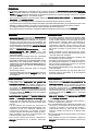 3
3
-
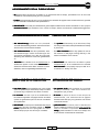 4
4
-
 5
5
-
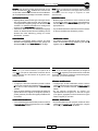 6
6
-
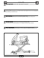 7
7
-
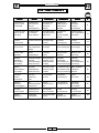 8
8
-
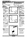 9
9
-
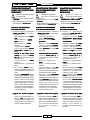 10
10
-
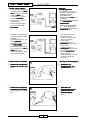 11
11
-
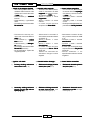 12
12
-
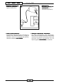 13
13
-
 14
14
-
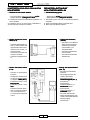 15
15
-
 16
16
-
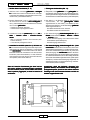 17
17
-
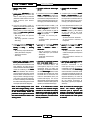 18
18
-
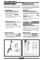 19
19
-
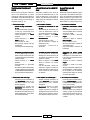 20
20
-
 21
21
-
 22
22
-
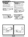 23
23
-
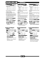 24
24
-
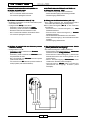 25
25
-
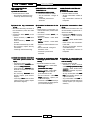 26
26
-
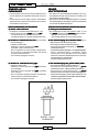 27
27
-
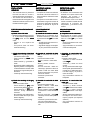 28
28
-
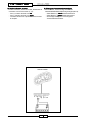 29
29
-
 30
30
-
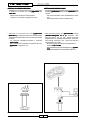 31
31
-
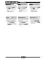 32
32
-
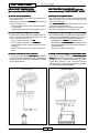 33
33
-
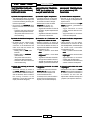 34
34
-
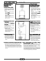 35
35
-
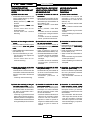 36
36
-
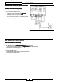 37
37
-
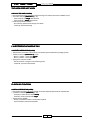 38
38
-
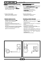 39
39
-
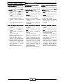 40
40
-
 41
41
-
 42
42
-
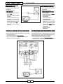 43
43
-
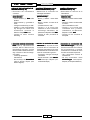 44
44
-
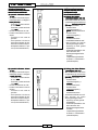 45
45
-
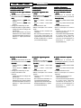 46
46
-
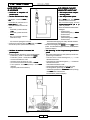 47
47
-
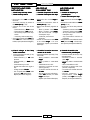 48
48
-
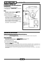 49
49
-
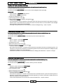 50
50
-
 51
51
-
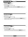 52
52
-
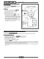 53
53
-
 54
54
-
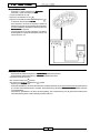 55
55
-
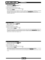 56
56
-
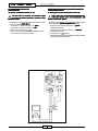 57
57
-
 58
58
-
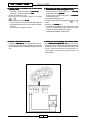 59
59
-
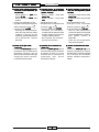 60
60
-
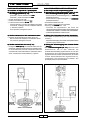 61
61
-
 62
62
-
 63
63


Malaguti F18 WARRIOR Electric System Troubleshooting
- Kategorie
- Kabelnetzwerktester
- Typ
- Electric System Troubleshooting
in anderen Sprachen
- English: Malaguti F18 WARRIOR
- français: Malaguti F18 WARRIOR
- español: Malaguti F18 WARRIOR
- italiano: Malaguti F18 WARRIOR
Verwandte Artikel
-
Malaguti F18 WARRIOR Benutzerhandbuch
-
-
-
-
-
Malaguti MADISON 180-200 Benutzerhandbuch
-
-
-
-