Hitachi 17MVX-v2 Benutzerhandbuch
- Kategorie
- Fernseher
- Typ
- Benutzerhandbuch
Dieses Handbuch ist auch geeignet für

Tt5CC-l
!=I
G
Colour Monitor
CM1721ME
User Manual
BEDIENUNGSANLEITUNG
17MVX-v2
For future references, record the serial number of your
display monitor, SERIAL No.
The
serial
number
is
located
on
the
rear
of
the
monitor.
READ
THE
INSTRUCTION
INSIDE
CAREFULLY.
KEEP
THIS
USER
MANUAL
FOR
FUTURE
REFERENCES
This monitor is
Energy
Star compliant when used with
a computer equipped with VESA DPMS.


For U.K. Customers
THIS
PRODUCT
IS
SUPPLIED WITH A TWO
PIN
MINS
PLUG
FOR USE
IN
MAINLAND EUROPE. FOR THE U.K.
PLEASE REFER
TO
THE NOTES
ON
THIS
PAGE.
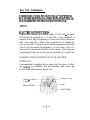
NOTE:
ELECTRICAL CONNECTIION
Your monitor requires an electrical supply of 240 volts
-
50 Hertz
and should be protected by a 5 amp fuse. Your equipment is
supplied with a plug incorporating a 5 amp fuse fitted to the mains
lead. If the plug that is fitted to the equipment is not suitable for
your socket outlet, it must be cut off and the appropriate plug fitted.
The cut off plug should be disposed of, do not insert it into a 13
amp socket to prevent the hazard of electric shocks. With plugs not
incorporating a fuse, the circuit must be protected by a 5 amp fuse.
WARNING: THIS EQUIPMENT MUST BE EARTHED.
IMPORTANT
Your equipment is supplied with a mains lead, the wires of which
are coloured in accordance with the following code: Green and
Yellow-Earth, Blue-Neutral, Brown-Live.
Green
&
Yellow
to Earth
Blue to Neutral
Brown to Live
Fuse
Cord
Clamp
-I-

As the
colours
of the
wires
in your mains lead in this equipment
may not correspond with the markings identified with the terminals
of your plug. proceed as follows:
The wire which is coloured Green and Yellow must be connected to
the terminal in the plug which is marked with the letter E or by the
symbol or coloured Green or Green and
Yellon,
The wire which is coloured Brown must be connected to the
terminal which is marked
with
the letter L or coloured Red.
The wire which is coloured Blue must be connected to the terminal
which is marked N or colourcd Black
The plug moulded on to the cord incorporates a fuse. For
replacement, use a
5
amp BS 1362 fuse. Only ASTA
approved
fuses should be used. The fuse cover/carrier must be refitted when
changing the fuse. In the event of losing the fuse cover/carrier, the
plug must not be used until a replacement has been obtained from
your nearest electrical
stockist
and fitted. The colour of the fuse
cover/carrier is that of the coloured marks on the insert in the base
of the plug.
-
II
-

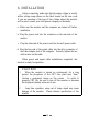
Please read the following instructions carefully to prevent
potential hazards. This manual should be retained for future use.
1. Do not expose the monitor to rain, water, moisture, or direct
sunlight.
2. Do not spill liquid into the monitor
3. Do not insert any objects into the monitor cabinet’s openings.
4. Do not place near or above sources of heat such as heaters or
radiators.
5. Do not block or cover ventilation opening with any material.
The openings and slots on the cabinet provide necessary air
flow for heat dissipation.
The unit should never be enclosed
or built upon unless adequate ventilation is provided.
6. Do not remove the cover to try to service this unit.
Servicing
of any nature should only be performed by authorized service
personnel.
7. WARNING! Do not attempt to service this unit yourself as
opening or removing covers may expose you to dangerous
voltage or other hazards.
8. The On/Off switch is not a disconnecting device. Make sure
to remove the AC power cord after using.
9. When the monitor is turned on continuously for a long period,
the phosphors of the CRT face plate may “bum” leaving a
permanent image on the screen.
In order to preserve CRT life,
be sure to turn off the monitor or decrease the displayed
intensity when not in use.
-
III
-

10. WARNING! The voltage ratings and the rated frequencies
are posted on the back panel of this product.
Please see
the
overlay in the center of the back panel of this product.
NEVER connect to any other voltage or frequency. Follow
ALL warnings and instructions marked on the product.
11. This, product is equipped with a
3-wire
grounding-type plug.
It will only fit into a grounding-type power outlet. This is a
safety feature. If you are unable to insert the plug into the
outlet, the outlet can be replaced by an electrician. Do not
defeat the safety purpose of the grounding-type plug by
improper use or alteration.
12.
Power source
. This monitor is able to operate using power sources from
108-264VAC/60-50Hz
by means of internal auto power
switching.
. For 120V operation, use only with power cord having a
parallel blade grounding-type plug, rated at I OA-
125V.
. For 240V operation, use only with power cord having a
tandem blade grounding-type plug
rated 1 OA-250V
minimum.
-
IV
-

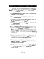
Bitte lesen Sie diese Sicherheitshinweise sorgftitig durch,
damit
die richtige Verwendung des Gerstes sichergestellt wird.
Diese Anleitung
sorg<ig
aufbewahren.
1. Das
Bildschirmger~t
nicht Regen, Wasser, Feuchtigkeit oder
direktem
Sonnenlicht
aussetzen.
2. Keine
Fltissigkeiten
tiber
dem Bildschirmgerat Verschtitten.
3. Niemals
Gegenstande
durch die
&fnungen
in das Innere des
Gerates
stecken oder hineinfallen
lassen.
4. Das
BildschirmgeCit
nicht in der Nahe von Heizgeraten der
Heizungen aufstellen.
5.
Nicht die beliiftungsdffhungen des Gehauses blockieren oder
abdecken. Diese
@frrungen
und
Schlitze
im Gehause sorgen
tir
die notwendige Ventilation. Das Bildschirmgerat sollte
niemals mit einer Verkleidung umgeben oder in einem Regal
eingebaut werden.
falls keine ausreichende
Beltiftung
vorhanden ist
6. Niemals versuchen, das Gehause zu entfemen oder das
Bildschirmgerat selber zu war-ten.
Alle
Wartungsarbeiten
sollten nur vom Kundendienst durchgefiihrt werden.
7. Nicht versuchen, das Bildschirmgerat selbst zu war-ten. Im
Inneren
des Gerates sind gef&rliche elektrische Spannungen
und andere Gefahren vorhanden.
8. Der Netzschalter ist keine Trennvorrichtung Sicherstellen,
daR
die
NetzanschluRleitung,
wenn das Gerat
Iangere
Zeit nicht
benutzt wird,
aus
der netzsteckdose gezongen wird.
-V-

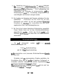
9.
Bei
Einstellung des Bildschinngerates auf
starkste
Helligkeit
und Kontrast uber langere Zeit Konnen die Leuchtschicht der
Bildrohrenoberfhiche
einbrennen.
Zur Verlangerung der
Lebensdauer der Bildrohre ist sicherzustellen,
dal3
das
Bildschirmgerat nach der Verwendung ausgeschaltet wird
oder Helligkeit und Kontrast verringert werden.
10. Die Angaben zur Spannung und Frequenz entnehmen Sie dem
Fabrikschild.
Schliessen Sie Ihr Gerat nie an eine
Stromquelle mit andeier. als der dort genannten Spannung/
Frequenz an.
Beachten
Sie ausserdem alle am Gerat
angebrachten Warn- und Bedienungshinweise.
11. Ihr Gerat ist mit einem dreipoligen Schukostecker ausgestattet.
Dieser Stecker kann nur an eine Schutzkontaktsteckdose
angeschlossen
wrerden.
Sollte der Stecker nicht in die
Steckdose
passen,
lassen
Sie diese bitte von einem Elektriker
auswechseln.
Es
mu8 sichergestellt werden.
dal3
die
minimale
Bildwiederholfrequenz von
70 Hz
bei
Positivdarstellung
und 60 Hz
bei
Negativdarstellung
nicht
unterschritten wird (storendes Bildschirmflimmem
konnte
die Folge sein).
Weiterhin wird
aus
ergonomischen Griinden empfohlen, die
Grundfarben Blau und Rot
nicht
auf dunklem Untergrund zu
verwenden (schlechte Lesbarkeit und erhohte Augenbelastung
bei
zu
geringem Zeichenkontrast
w&ren
die Folge).
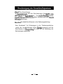
“Der
arbeitsplatzbezogene Schalldruckpegel
nach
DIN 45 635 Teil
1000 betragt
70dB(A)
oder
weniger”
-
VI
-

(Gerat,
Typ, Bezeichnung)
in ijbereinstimmung mit den Bestimmungen der
BMPT-Amt-
sblVfg
243/l 99 1 funk-entstort ist.
Der
vorschriftsmai3ige
Betrieb
mancher Gerate
(zB
Me&sender)
kann allerdings gewissen Ems&r
ankungen
unterliegen.
Beachten Sie deshalb die Hinweise in der Bedienungsanleitung.
Dem Bundesamt’ fur Zulassungen in der Telekommunikation
wurde das inverkehrbringen dieses
Gerates
angezeigt und die
Berechtigung zur ijberprtifung der Serie auf die Einhaltung der
Bestimmungen eingeraumt.
-
VII
-

/
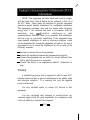
NOTE: This equipment has been tested and found to comply
with the limits for a Class B digital device, pursuant to Part 15 of
the FCC Rules. These limits are designed to provide reasonable
protection against harmful interference in a residential installation.
This equipment generates. uses and can radiate radio frequency
energy and, if not installed and used in accordance with the
instructions.
may
cause harmful interference to
radio
communications. However, there is no guarantee that interference
will not occur in a particular installation. If this equipment does
cause harmful interference to radio or television reception, which
can be determined by turning the equipment off and on, the user is
encouraged to try to correct the interference by one or more of the
following measures:
-
Reorient or relocate the receiving antenna.
-
Increase the separation between the equipment and receiver.
-
Connect the equipment into an outlet on a circuit different from
that to which the receiver is connected.
-
Consult the dealer or an experienced radio/TV technician for
help.
Warning:
A shielded-type power cord is required in order to meet FCC
emission limits and also to prevent interference to the nearby radio
and television reception.
It is essential that only the supplied
power cord be used.
Use only shielded cables to connect l/O devices to this
equipment.
You are cautioned that changes or modifications not
expressly approved by the party responsible for compliance could
void your authority to operate the equipment.
-
VIII
-

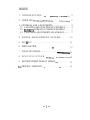
INDEX
1.
INTRODUCTION..
_.
. .
_.
.
.
.
.
.
.
.
.
.
.
.
.
.
.
.
.._..
.
.
.
.
.
.
.
.
.
.
.
.
.:..
2
2.
CHECK LIST .._............... .
_.......___......
. . . . . . .
..____...............
3
3. CONTROLS AND ADJUSTMENTS
................................
4
3.1
LOCATION AND FUNCTION OF CONTROLS..
.......
4
3.2
REWRITE COMPANY’S NAME ON SCREEN 1
......
7
3.3
FUNCTIONS ADJUSTMENTS ON SCREEN 2..
........
7
4.
POWER MANAGEMENT SYSTEM.. . . . .
10
5.
PLUG
&
PLAY.. . . . . . . . . . . . . . . . . . . . . . . . . . . . . . . . . . . . . . . . . . . . . . . . . . . . .
11
6.
INSTALLATION..
_.
.
12
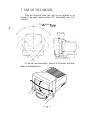
7.
USE OF TILT-SWIVEL.. . . . . . . . . . . . . . . . . .
.
.
.
.
.
.
.
.
.
.
.
.
.
.
.
.
.
.
.
.
.
.
13
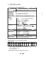
8.
SPECIFICATION
___......____.
.
..____
_.
_.
._____.__...
14
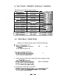
9.
FACTORY PRESET DISPLAY MODES
t...
. . . . . . . . . . . .
15
10.
TROUBLE SHOOTING..
_.
. . . . . . . . .
_.
. . . . . .
15
-I-

1. INTRODUCTION
This colour monitor is an excellent choice for high resolution
compatibility, versatility and quality.
It automatically scans
horizontal frequencies
between 30 and 64 kHz and vertical
frequencies between 47 and 104 Hz and is equipped with an Easy
Menu microprocessor controlled multi-frequency function.
This monitor offers compatibility with virtually every major
high resolution video board for PC and video standards including
VGA, SVGA. XGA, VESA and is even compatible with APPLE
MAC
II
by using an inexpensive optional connector.
The 1280 X 1024 maximum resolution will help you get the
most flexibility with today’s or tomorrow’s PC video standards.
Whether your video adapter has a multi-frequency or
fixed-
frequency analog colour signal, it will interface with this colour
monitor.
The unit is also equipped with an energy-saving function. It
is compatible with the EPA Energy Star
&
VESA DPMS power-
saving standards.
. VGA, SVGA, XGA, APPLE MAC
II:
EPA, and VESA are
trademarks of their respective owners.
-2-

2. CHECK LIST
Before installation, please check the contents of the shipping
carton. The carton should contain the following items:
-
Power cord
-
User manual
-
Colour monitor
If any of the above items are missing, contact your supplier as
soon as possible.
-3-

3. CONTROLS AND ADJUSTMENTS
3.1 LOCATION AND FUNCTION OF CONTROLS
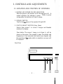
1. POWER AND POWER SAVING INDICATOR
When the power to the monitor is ON, the indicator is lit.
In
normal operation, the indicator is green.
While in power
saving mode, the indicator will turn to orange.
2. POWER SWITCH
Used to turn the power of the monitor ON and OFF
3. STATUS SELECT SWITCH (Easy Menu)
Selects from screen 1 or screen 2 images and blanked
windows for display.
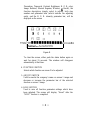
Press button. The screen 1 image, as in figure A, will be
shown on the screen. The company’s name, the polarity and
frequencies of the horizontal and vertical sync signals, and
the resolution of the mode which is currently in use now will
be displayed.
Front View
-4-
161/5/
10
STANS,
il
1s
I

Company’s Name
Frequency & Polarity of
Horizontal Sync Signal
Frequency
&
Polarity of
Vertical Sync Signal
Mode Resolution in Use
Figure A
Press button again and the screen 2 image as in figure B will
appear on the screen. The
tinction
symbols (including
Horizontal size and phase, Vertical size and center,

Pincushion, Trapezoid, Contrast, Brightness, R. G. B. color,
Image Rotation, Manual Degauss, Window,
&
Recall), the
function description (simply select to adjust). both step
number and parameter bars (which indicate the adjusting
scale), and the R. G. B. intensity parameter bar,
will be
displayed
on the screen
Step
Nc
@)RGBB
-fwElcl
-2551BIIIIIIIIIm--
Contrast-
Function Description
--F
‘ammeter
Bar
Figure B
To clear the screen, either push the status button again or
wait for about 15 seconds. The window will disappear
automatically at that time.
4. FUNCTION SWITCH
Selects which function on screen 2 to be adjusted
5. ADJUST SWITCH
Used to rewrite the company’s name on screen 1 image and
decrease or increase the parameter bar of the selected
function on screen 2 image.
6. SAVE SWITCH
Used to save all function parameter settings which have
been adjusted. The screen will display “Saved” after the
“SAVE” function is completed.
-6-

*Total 32 different modes can be stored in memory and
automatically recalled.
12 of them are factory preset for
popular graphic standards (see Factory Preset Display Mode
on page 15). The remaining 20 modes are reserved for user
setting.
3.2 REWRITE COMPANY’S NAME ON SCREEN 1
The company’s name of this monitor can be rewritten by the
retailer or end-user. The new company’s name may contain up to
10 characters. Press function keys
"a"
or “D” as shown in item 4
on page 6 to select the character you wish to rewrite and then
continuously press the adjust switch
“-”
or
“f”
in order to select
a letter or number. The alphabet and numerals will be displayed
in sequence.
Press “SAVE” key to save new company’s name
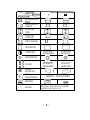
3.3 FUNCTIONS ADJUSTMENTS ON SCREEN 2
For each
fimction
control, use the adjustment switch’s “t”
and
11-11
buttons to adjust the monitor’s parameter bars to your
satisfaction according to the following table:
-7-

-
El
HORIZONTAL
SIZE
El
E3
ID
HORIZONTAL
PHASE
cl
I
cl
I
El
VERTICAL
SIZE
czl
lxl
?I
VERTICAL
CENTER’
cl
El
I
El
pa
PINCUSHION
0
>
n
TRAPEZOID
I
\
CD
CONTRAST
CONTRAST
CONTRAST
INCREASED
REDUCED
a
BRIGHTNESS
-e
-G-
R
2
COLOR
lNTENSlN
INTENSITY
INCREASED
REDUCED
@
IMAGE
ROTATION
01
o\
-R-
CRT
DEGAUSSING
MANUAL DEGAUSSING
-
-
cl
-
WINDOW
I
I-]
El
I’=]
cl
RECALL
RECALLS THE FACTORY PRESET
MODES-SEE PAGE 15
-8-

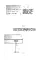
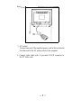
Rear
View
1. AC socket
Connect one end of the supplied power cord to this socket and
the other end to the AC power outlet of the computer.
2. Connect video cable with 15 pin male D-SUB connector to
the PC Video card.
-9-

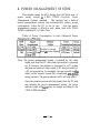
4. POWER MANAGEMENT SYSTEM
This monitor meets the EPA Energy Star (30 Watts max. at
power
saving
mode)
&
VESA DPMS (Display
Power
Management System) standard.
The monitor has a built-in
power management system that automatically reduce power
consumption’ when the PC is not in use.
And the power
management system is effective only when used with VESA
DPMS compliant PC or Video Card.
Table of Power Consumption in each Advanced Power
Switches to saving
mode
&
screen darkens
Note: The power management system is initiated by the video
signal sent from the PC side when the monitor is powered
on. If. however. the monitor is connected to a PC system
that does not send out video signal (a PC dead on arrival or
a PC not powered on, for example), the user can still see
the
raster on the monitor screen like a traditional
non-power-
saving monitor. The power indicator LED will stay green,
Once the monitor receives the first signal from the PC side
and initiates the power management system, the power
indicator light will turn green or orange according to the
VESA DPMS standard.
-
10
-
Seite laden ...
Seite laden ...
Seite laden ...
Seite laden ...
Seite laden ...
-
 1
1
-
 2
2
-
 3
3
-
 4
4
-
 5
5
-
 6
6
-
 7
7
-
 8
8
-
 9
9
-
 10
10
-
 11
11
-
 12
12
-
 13
13
-
 14
14
-
 15
15
-
 16
16
-
 17
17
-
 18
18
-
 19
19
-
 20
20
-
 21
21
-
 22
22
-
 23
23
-
 24
24
-
 25
25


Hitachi 17MVX-v2 Benutzerhandbuch
- Kategorie
- Fernseher
- Typ
- Benutzerhandbuch
- Dieses Handbuch ist auch geeignet für
in anderen Sprachen
- English: Hitachi 17MVX-v2 User manual
Verwandte Papiere
Sonstige Unterlagen
-
Fujitsu 19P2 Benutzerhandbuch
-
Fujitsu Siemens Computers 21P3 Bedienungsanleitung
-
Princeton AGX700 Benutzerhandbuch
-
NEC DiamondPlus 200 Bedienungsanleitung
-
-
NEC Diamond Pro 920 Bedienungsanleitung
-
-
-
Mitsubishi Electronics 2060u Benutzerhandbuch
-
Daewoo 103FH Benutzerhandbuch