
Technical Manual
Technisches Handbuch
Livret technique
Technisch boek
Manual tehnic
EN
ERV HEAT RECOVERY UNIT
0661030_R11
DE
FR
NL
RO

2

3
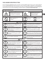
EN
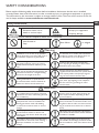
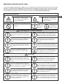
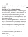
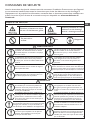
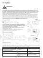
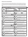
SAFETY CONSIDERATIONS
Please read the following safety instructions before installation. And ensure that the unit is installed
correctly. Please observe all instruction in order to avoid any injury or damage to equipment or property.
The information in this document is subject to change without notice. The most recent version of this ma-
nual is always available at www.markclimate.com/downloads.
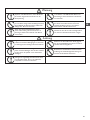
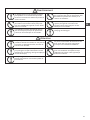
Safety attentions
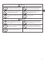
The following symbols indicate potential levels of caution.
The following symbols indicate compliance which must be observed
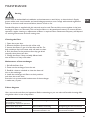
Warning
Attention
Installation to be carried out by qualied
person, End Users must not install, move or
re-install this equipment by themselves.
Power cable and wires must be installed
by a qualied electrical engineer. Improper
connection can cause over heating. Fire and
loss of efciency.
Insulation between the metal ducting and
wall penetration must be installed if the
ducting penetrates metal wall cladding,
to avoid risk of electric shock or current
leakage.
Use only approved installation hardware
and accessories. Failure to observe can
result in re risk, electric shock and equip-
ment failure.
The outdoor ducts must be installed facing
downwards to avoid rain water entering.
Improper installation can cause water
leakage.
Where the unit is positioned, at high level in
a hot humid situation. Please ensure sufcient
ventilation is available.
Correctly sized MCB must be tted to the
unit suitable earth leakage protection should
also be installed to avoid risk of electric shock
or re.
The cover of wiring box must be pressed
down and closed to avoid dust and dirt ente-
ring. Excess dust and dirt can cause over-hea-
ting of terminals and result in re or electric
shock.
Installation engineers must follow this man-
ual strictly. Improper action can create a
health hazard and reduce efciency of the
unit.
Unit must be installed strictly following this
manual and mounted to a weight bearing
surface for the weight of the unit.
During maintenance or repair, the unit
and circuit breaker must be switched off.
Other-wise electric shock could occur.
An anti-bird net or similar device should be
installed to outside vents. Ensure there are
no obstructions to or in the ducts.
To avoid condensation, insulation should be
tted to fresh air ducts. Other ducting may
also require insulation depending on dew
point conditions.
Fresh air vent must be far enough away
from any ue gas discharge or areas where
hazardous vapors are present.
Electric engineering must follow national
regulations and the manual, use special cables.
Less capacity cables and improper enginee-
ring can cause electric shock or re.
Ground wire cannot be connected to gas
pipe, water pipe, lighting rod or telephone
line etc. Incorrect grounding can cause
electric shock.
Not allowed or
Stop
Must follow or obliged
Situations with a risk
of injury or equipment/
property damage.
Situations with a risk or
death or serious injure.

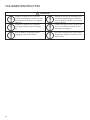
4
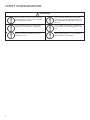
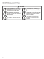
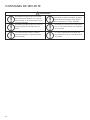
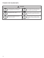
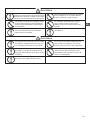
Attention
Do not install the unit in an extremely hu-
mid conditions, as it may result in electric
shock and pose a re risk.
Do not install the unit in areas there any
poisonous or caustic gases are present.
Acidic or alkali environments can cause
poisoning or a re.
Do not use the units as the primary kit-
chen extract grease and fatty deposits can
block the heat exchanger, lter and pose a
re risk.
Do not install the unit near open ame as
it may result in over heating and pose a re
risk.
Rated supply voltage must be maintained,
otherwise this may cause re.
SAFETY CONSIDERATIONS

5
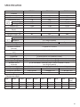
EN
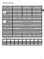
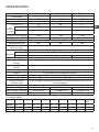
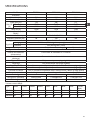
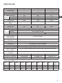
SPECIFICATIONS
Model ERV500 ERV1000 ERV2000
Performance
Airow(m3/h) 500 1000 2000
External pressure 50 120 120
Airow (l/s) 143 286 571
heating 67-75 71-78 71-78
cooling 62-74 65-74 65-74
Temp. Eff (%) 75-86 75-85 75-85
Noise (1m) Db(A)* 39 43 51.5
Power Supply 220-240V/1Ph/50Hz
Input Power (W) 88 243 486
Power Cable 2x1.5mm
2
Control Cable 2x0.5mm
2
(Shielded data cable, max. 10 meter)
Standard Yes (7-Day Time-clock)
(BMS) Modbus
Yes Optional
Fan Type DC Fan Motors
Fan Speeds (Supply) 10 Speed Fan Control
Fan Speeds (Exhaust) 10 Speed Fan Control
Summer Bypass Yes (Automatic with adjustable range)
Defrost Yes (Automatic with adjustable range)
CO
2
Control Optional controller available (On / Off control with adjustable range)
Humidity Control Optional controller available (On / Off control with adjustable range)
Fan Boost Contacts Yes (3x available connection to Contact: Closed = Boost to High Speed)
Fire Shutdown Yes (1x available connection to Contact: Closed = Shutdown)
Weight (Kg) 43 83 189
Size (WxHxD) 904x270x962 1134x388x1322 1134x785x1322
Duct Size 200 250 300
* Sound level dB(A):
Type 63Hz 125Hz 250Hz 500Hz 1kHz 2kHz 4kHz 8kHz Overall
dB(A)
ERV500 34 40 35 35 36 28 22 17 39
ERV1000 38 44 39 41 40 31 31 19 43
ERV2000 45 52 46 48 48 48 37 23 51
Enth.
Eff (%)
Control

6
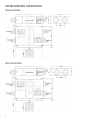
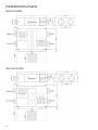
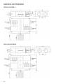
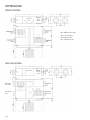
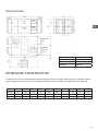
DIMENSIONED DRAWINGS
ERV1000 MODEL
ERV500 MODEL

7
EN
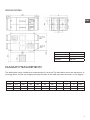
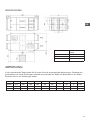
ERV2000 MODEL
Model Dia. (mm)
ERV500 ø 200
ERV1000 ø 250
ERV2000 280*650
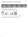
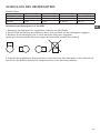
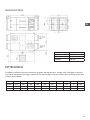
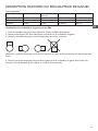
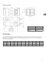
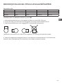
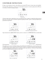
DIAGRAM MEASUREMENTS
The table below shows suitable duct measurements for each unit. The table below shows the dimensions of
the image above and the two images previously, the letter in the table represents the letter on the diagram .
Model L L1 W W1 W2 H H1 C G N
ERV500 962 890 904 960 500 270 111 107 19
ø 194
ERV1000 1322 1250 1134 1190 678 388 170 85 19
ø 242
ERV2000 1322 1250 1134 1190 678 785 170 150 19 280*650

8
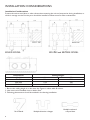
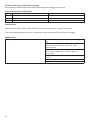
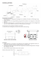
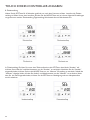
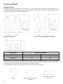
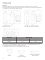
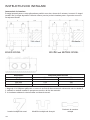
INSTALLATION CONSIDERATIONS
Installation Considerations
Protect the unit to avoid dust or other obstructions entering the unit and accessories during installation, or
whilst in storage on site. Service ports should be installed to allow access for lter maintenance.
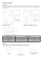
1. Be sure the ceiling height is no less than the Figures in above table B column.
2. Unit must not be installed close to boiler ues.
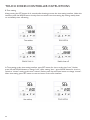
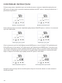
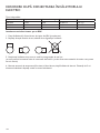
3. Following phenomenon should be avoided in the ducting installation.
Dimensions Celling Height
Model A B
ERV500 904 320
ERV1000 1134 440
ERV2000 1134 835
Serve bends Multiple direction changes
Multiple reducers/
crimped duct
ERV500 MODEL ERV1000 and ERV2000 MODEL

9
EN
INSTALLATION CONSIDERATIONS
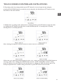
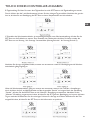
4. Excessive use of ex-duct and long ex-duct runs should be avoided.
5. Fire dampers must be tted as per national and local re regulations.
6. Unit must not be exposed to ambient temperature above 40°C and should not face an open re.
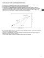
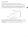
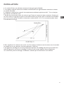
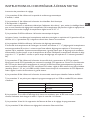
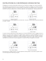
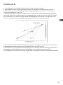
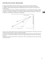
7. Take action to avoid dew and frost. As shown by drawing below, unit will produce dew or frost when
saturation curve is formed from A to C. Use pre-heater to ensure conditions are kept to right of the
curve (B to B’,to move C to C) to prevent condensation or frost formation.
8. To avoid the outdoor exhaust air cycling back to indoor, the distance between the two vents installed on
the outside wall should be over 1000mm.
9. If heater is equipped to the unit, operation of heater should be synchronous with the unit, so that the
heater starts to work only when unit starts.
10. Duct mufer may be considered if user wants indoor noise to be minimized.

10
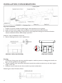
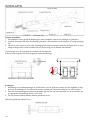
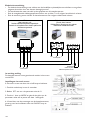
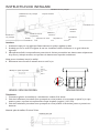
INSTALLATION CONSIDERATIONS
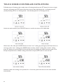
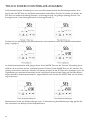
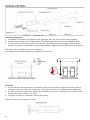
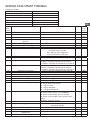
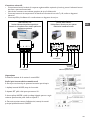
Physical Installation
1. Installer to prepare suitable threaded hangers with adjustable nuts and gaskets.
2. Install as shown by the image above. Installation must be level and securely fastened.
3. Failure to observe proper xing could result in injury, equipment damage and excessive vibration.
Uneven installation will also effect damper operation.
Notes for reverse installation of the unit
4. Reverse labeling shows the unit is upside down.
Ducting
1. Connection of unit vents and ducts should be taped or sealed to prevent air leakage, and should com-
ply to relevant guidelines and regulations.
2. The two outdoor vents should face downward toward the outside to prevent any rain water ingress.
(angle 1/100 1/50).
3. Insulation must be with the two ducts outside to prevent condensation.
Material: glass cotton, Thickness: 25mm
NUT
WASHER
BRACKET
WASHER
NUT
ERV500 / ERV1000 MODEL ERV2000 MODEL

11
EN
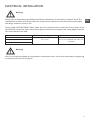
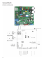
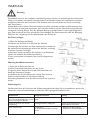
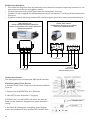
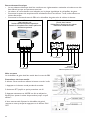
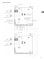
ELECTRICAL INSTALLATION
Warning
Warning
Power must be isolated during installation and before maintenance to avoid injury by electric shock. The
specications of cables must strictly match the requirements, otherwise it may cause performance failure
and danger of electric shock or re.
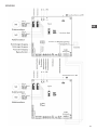
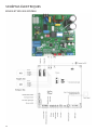
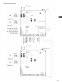
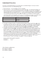
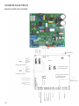
Power supply is AC220V/50HZ/1 Phase. Open the cover of electrical box, connect the 2 wires (L/N/) to the
terminals and connect the cable of the control panel to the board according to the wiring diagram, and join
the control panel to the cable.
We do not accept any liability for any problems caused by the user’s self and non-authorized re-engineering
to the electrical and control systems.
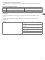
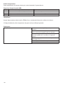
Model Spec. of power supply cable Spec. of normal controller cable
ERV500
2 x 1.5 mm² 2 x 0.5 mm² (Shielded data cable, max.
10 meter)
ERV1000
ERV2000

12
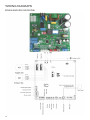
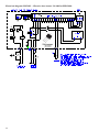
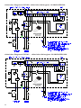
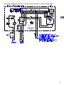
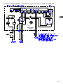
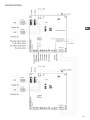
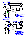
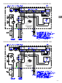
WIRING DIAGRAMS
ERV500 AND ERV1000 MODEL

13
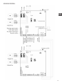
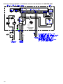
EN
ERV2000 MODEL

14
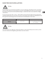
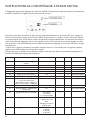
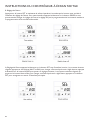
COMMISSIONING
Check that all cable sizes, circuit breakers and wire connections are correct before following below com-
missioning steps:
1. Press button to turn on/off the ventilator.
2. Match the correct speed to ERV. Press for 6 seconds to enter parameters setting and at this time the
parameter number is shown in the middle of the screen, press button to switch to parameter No. 21
(refer to parameters list in comming page) then press shortly to enter the parameter setting, default
value “0” esh at the top right corner, press UP and DWON buttons to change the value according to
below table (ERV code Vs Models) then press button again to conrm setting. With the same way to
change parameters number 23 to be value 2 (10 speeds DC fan control).
Code Models
3 ERV500
2 ERV1000
2 ERV2000
3. Then check the mode and fan speed switch. Press button shortly to switch to OA, RA, SA or EA
mode*, check whether the temperature of the corresponding mode is correct. Under SA or RA mode,
Press to switch the fan speed, check if the airow is adjusted corresponding to H speed ,
M speed and L speed .
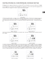
4. Check the operation of bypass. The default opening temperature of bypass is 19-21C (adjustable),
press button to check the temperature of OA. If the present OA temperature is among 19-21C,
then bypass will open automatically. If the OA temperature is not within 19-21C, say 18C, then press
button more than 6 seconds to enter the parameter setting. Press button to switch to parameter
number 02, default value 19 ashes shown at the top right corner. Then press button shortly to
enter setting, by pressing buttons and set the value to be “X”. Then press to conrm.
To test that the bypass opens, the temperature OA must be greater than or equal to value "X" of para-
meter 02 and less than value "X + Y" of parameters 2 and 3 together. X = OA < (X + Y)
Note: the opening / closing of the bypass will be delayed for about 1 minute.
Note: reset the values after this test!
Parameter 2: X = 19
Parameter 3: Y = 3
*OA = Outdoor air
RA = Extract air
SA = Supply air
EA = Exhaust air

15
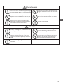
EN
Loose or incorrect wiring connection can
cause explosion or re when the unit starts
to work. Use only rated power voltage.
Don’t site intake supply vent in hot and
humid conditions , as it may cause failure,
current leakage or re.
Don’t install, move or re-install the unit by
yourself. Improper action may cause unit
instability, electric shock or re.
Isolate power during extended off periods
Isolate power and take care when cleaning
unit. (Risk of electric shock)
Running the unit continuously in an abnor-
mal status may cause failure, electric shock
or re.
Clean the lter regularly. A blocked lter
may result in poor indoor air quality.
Don’t put ngers or objects into vents of
fresh air or exhaust air supply. Injury may be
caused by the rotation of the impeller.
Don’t put any burner directly facing the
fresh air discharge, otherwise it may cause
an insufcient burning.
Don’t change, disassemble or repair the
unit by yourself. Improper action may
cause electric shock or re.
Observe guidelines and regulations rela-
ting to incomplete combustion when use
is asso-ciated with fuel burning appliances.
Switch off the power and breaker when you
clean the exchanger.
Warning
Attention

16
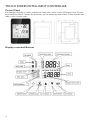
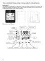
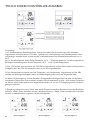
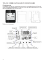
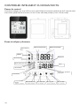
TOUCH SCREEN INTELLIGENT CONTROLLER
Control Panel
The intelligent controller is surface mounted and comes with a touch screen LCD display screen. The stan-
dard connection cable is 5 meters, but if necessary you can extend this with another 5 meter shielded data
cable (= max. 10 meter total).
Display screen and Buttons

17
EN
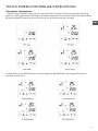
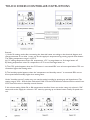
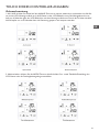
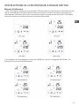
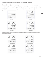
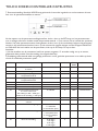
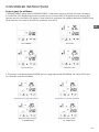
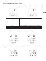
TOUCH SCREEN CONTROLLER INSTRUCTIONS
Operation Instructions
1. ON/OFF: press ON/OFF button once for starting; twice for closing. In ON status, backlit LCD display
lights up, in OFF status, backlit LCD display off, without operation for 6 seconds, backlit LCD display off too.
By pressing ON/OFF button for around 6 seconds can lock and unlock the controller.
2. Mode switch: press MODE button to choose display the RA-OA-FR(EA)- SA Setting-CO2 status or
Humidity control status.

18
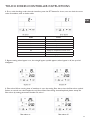
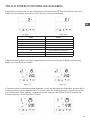
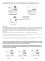
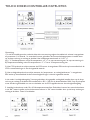
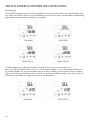
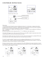
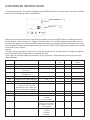
TOUCH SCREEN CONTROLLER INSTRUCTIONS
Remark:
1) Under SA setting mode, after connecting the electrical heater according to the electrical diagram and
change parameter 01 to value 1, users can set the supply air temperature by pressing up and down button.
The setting temperature range is 10-25°C.
A) 0°C setting temperature minus SA temperature <5°C 1st stage heater on, 2nd stage heater off
B) Setting temperature minus SA temperature >5°C1st and 2nd stage heater on
2) The CO2 symbol appears when the CO2 sensor is connected. ERV runs at boost speed when CO2 con-
centration higher than setting value.
3) The humidity symbol appears when the “temperature and humidity sensor” is connected. ERV runs at
boost speed when humidity higher than setting value.
Under “humidity control” mode, users can set the setting humidity by pressing up and down button. The
setting range is 45% ~ 90%. And the Dial switch SW4-3 on the PCB should be switched ON to switch from
CO2 control function to humidity control function.
3. Air volume setting: Under SA or RA temperature interface. Users can set the return air volume in “RA”
status, and set the supply air volume in “SA” status by pressing up and down button. Totally 10 speeds con-
trol.

19
EN
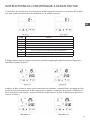
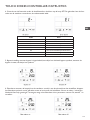
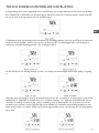
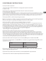
TOUCH SCREEN CONTROLLER INSTRUCTIONS
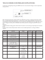
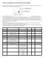
4. Error code checking: under the main interface, press the SET button for short, user can check the error
code of ventilator, refer to below table.
5. Bypass setting: when bypass is on, the triangle bypass symbol appears, when bypass is off, the sym-bol
disappears.
6. Filter alarm: When running time of ventilator is over the setting lter alarm time, the lter alarm symbol
ashes to remind user clean/replace the air lters. After lters being cleaned/replaced, please sweep the
lter alarm by setting parameter Number 24, value 1.
Code Error
E1 Fresh air temperature sensor error
E2 EEPROM error
E3 Return air temperature sensor error
E4 Exhaust air temperature sensor error
E5 Communication error
E6 Supply air temperature sensor error
E7 Exhausted fan error
E8 Supply fan error

20
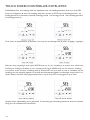
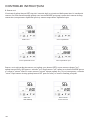
TOUCH SCREEN CONTROLLER INSTRUCTIONS
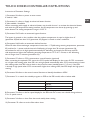
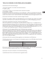
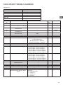
7. Parameters setting: Keep pressing the MODE button for 6 seconds, after buzzing to enter the parameter
setting interface.
After entering the parameter setting interface, press SET button shortly to change the parameter number,
every pressing will make parameter value +1 (until number 24 then repeat again). After choosing the cor-
rect parameter number, press Mode button for short, parameter value ashes at the top right corner, at this
time to change the value by UP and DOWN buttons. After parameters setting then press SET button to
save.
Attention:
1) After parameters setting, system need around 15 seconds to record, during this period power should not
be off.
2) Please refer to below valid parameters table to set the suitable parameters according to different
requests.
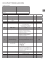
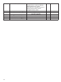
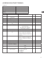
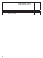
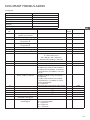
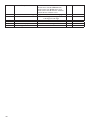
No. Contents Range Default Unit Record Position
00 Power to auto restart 0-1 1 Main control
01 Electrical heater available 0-1 0 Main control
02 Bypass opening
temperature X
5-30 19 °C Main control
03 Bypass opening
temperature range Y
2-15 3 °C Main control
04 Defrosting interval 15-99 30 Minute Main control
05 Defrosting entering temperature -9-5 -1 °C Main control
06 Defrosting duration time 2-20 10 Minute Main control
07 CO2 sensor function value
0 = No CO2 sensor
80 = 800 ppm, 250 = 2500 ppm
Advised setting = 1000 ppm
0 / 80-250 0 PPM Main control
08 ModBus address 1-16 1 Main control
21 ERV models match/
selection
0-7 Main control
23 Fan speed control 0: 2 speeds
1: 3 speeds
2: 10 speeds (DC)
2
24 Multifunction setting 0: Reserved
1: Sweep lter alarm
2: sweep weekly timer
0
25 Filter alarm setting 0: 45 days
1: 60 days
2: 90 days
3: 180 days
0
Seite laden ...
Seite laden ...
Seite laden ...
Seite laden ...
Seite laden ...
Seite laden ...
Seite laden ...
Seite laden ...
Seite laden ...
Seite laden ...
Seite laden ...
Seite laden ...
Seite laden ...
Seite laden ...
Seite laden ...
Seite laden ...
Seite laden ...
Seite laden ...
Seite laden ...
Seite laden ...
Seite laden ...
Seite laden ...
Seite laden ...
Seite laden ...
Seite laden ...
Seite laden ...
Seite laden ...
Seite laden ...
Seite laden ...
Seite laden ...
Seite laden ...
Seite laden ...
Seite laden ...
Seite laden ...
Seite laden ...
Seite laden ...
Seite laden ...
Seite laden ...
Seite laden ...
Seite laden ...
Seite laden ...
Seite laden ...
Seite laden ...
Seite laden ...
Seite laden ...
Seite laden ...
Seite laden ...
Seite laden ...
Seite laden ...
Seite laden ...
Seite laden ...
Seite laden ...
Seite laden ...
Seite laden ...
Seite laden ...
Seite laden ...
Seite laden ...
Seite laden ...
Seite laden ...
Seite laden ...
Seite laden ...
Seite laden ...
Seite laden ...
Seite laden ...
Seite laden ...
Seite laden ...
Seite laden ...
Seite laden ...
Seite laden ...
Seite laden ...
Seite laden ...
Seite laden ...
Seite laden ...
Seite laden ...
Seite laden ...
Seite laden ...
Seite laden ...
Seite laden ...
Seite laden ...
Seite laden ...
Seite laden ...
Seite laden ...
Seite laden ...
Seite laden ...
Seite laden ...
Seite laden ...
Seite laden ...
Seite laden ...
Seite laden ...
Seite laden ...
Seite laden ...
Seite laden ...
Seite laden ...
Seite laden ...
Seite laden ...
Seite laden ...
Seite laden ...
Seite laden ...
Seite laden ...
Seite laden ...
Seite laden ...
Seite laden ...
Seite laden ...
Seite laden ...
Seite laden ...
Seite laden ...
Seite laden ...
Seite laden ...
Seite laden ...
Seite laden ...
Seite laden ...
Seite laden ...
Seite laden ...
Seite laden ...
Seite laden ...
Seite laden ...
Seite laden ...
Seite laden ...
Seite laden ...
Seite laden ...
Seite laden ...
Seite laden ...
Seite laden ...
Seite laden ...
Seite laden ...
Seite laden ...
Seite laden ...
Seite laden ...
Seite laden ...
Seite laden ...
Seite laden ...
Seite laden ...
Seite laden ...
Seite laden ...
Seite laden ...
Seite laden ...
Seite laden ...
Seite laden ...
Seite laden ...
Seite laden ...
-
 1
1
-
 2
2
-
 3
3
-
 4
4
-
 5
5
-
 6
6
-
 7
7
-
 8
8
-
 9
9
-
 10
10
-
 11
11
-
 12
12
-
 13
13
-
 14
14
-
 15
15
-
 16
16
-
 17
17
-
 18
18
-
 19
19
-
 20
20
-
 21
21
-
 22
22
-
 23
23
-
 24
24
-
 25
25
-
 26
26
-
 27
27
-
 28
28
-
 29
29
-
 30
30
-
 31
31
-
 32
32
-
 33
33
-
 34
34
-
 35
35
-
 36
36
-
 37
37
-
 38
38
-
 39
39
-
 40
40
-
 41
41
-
 42
42
-
 43
43
-
 44
44
-
 45
45
-
 46
46
-
 47
47
-
 48
48
-
 49
49
-
 50
50
-
 51
51
-
 52
52
-
 53
53
-
 54
54
-
 55
55
-
 56
56
-
 57
57
-
 58
58
-
 59
59
-
 60
60
-
 61
61
-
 62
62
-
 63
63
-
 64
64
-
 65
65
-
 66
66
-
 67
67
-
 68
68
-
 69
69
-
 70
70
-
 71
71
-
 72
72
-
 73
73
-
 74
74
-
 75
75
-
 76
76
-
 77
77
-
 78
78
-
 79
79
-
 80
80
-
 81
81
-
 82
82
-
 83
83
-
 84
84
-
 85
85
-
 86
86
-
 87
87
-
 88
88
-
 89
89
-
 90
90
-
 91
91
-
 92
92
-
 93
93
-
 94
94
-
 95
95
-
 96
96
-
 97
97
-
 98
98
-
 99
99
-
 100
100
-
 101
101
-
 102
102
-
 103
103
-
 104
104
-
 105
105
-
 106
106
-
 107
107
-
 108
108
-
 109
109
-
 110
110
-
 111
111
-
 112
112
-
 113
113
-
 114
114
-
 115
115
-
 116
116
-
 117
117
-
 118
118
-
 119
119
-
 120
120
-
 121
121
-
 122
122
-
 123
123
-
 124
124
-
 125
125
-
 126
126
-
 127
127
-
 128
128
-
 129
129
-
 130
130
-
 131
131
-
 132
132
-
 133
133
-
 134
134
-
 135
135
-
 136
136
-
 137
137
-
 138
138
-
 139
139
-
 140
140
-
 141
141
-
 142
142
-
 143
143
-
 144
144
-
 145
145
-
 146
146
-
 147
147
-
 148
148
-
 149
149
-
 150
150
-
 151
151
-
 152
152
-
 153
153
-
 154
154
-
 155
155
-
 156
156
-
 157
157
-
 158
158
-
 159
159
-
 160
160


Mark ERV Series Technical Manual
- Kategorie
- Split-System-Klimaanlagen
- Typ
- Technical Manual
in anderen Sprachen
- English: Mark ERV Series
- français: Mark ERV Series
- Nederlands: Mark ERV Series
- română: Mark ERV Series
Sonstige Unterlagen
-
LG LZ-H200GBA2 Benutzerhandbuch
-
Tristar KA-5860 Series Benutzerhandbuch
-
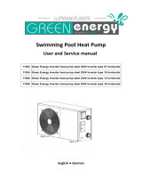 Green Energy Inverter Eco 7 User And Service Manual
-
Maico Trio Series Operating Instructions Manual
-
Salda RIS 400PE EKO 3.0 Technical Manual
-
LG PRCKD21E.ENCXIDA Bedienungsanleitung
-
Maico WS 320 Commissioning And Maintenance Instructions
-
Aldes Dee Fly Cube 550+ Installation Instructions Manual
-
 hydro-s Inverter 20 User And Service Manual
-
mundoclima MUEX-H9 “MultiSplit System” Installationsanleitung

