
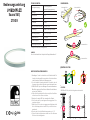
Bedienungsanleitung
Sauna SVQ
2700 K
WICHTIGE INSTALLATIONSHINWEISE:
1. Beauftragen Sie mit der Installation eine Elektrofachkraft. Für
Leuchten, die nicht gemäß den europäischen Sicherheitsrichtlinien
installiert wurden, entfällt jeder Haftungsanspruch.
2. Vor der Installation Spannung abschalten. Sicherstellen, dass die
Spannung nicht versehentlich wieder eingeschaltet werden kann.
3. VARDAflex LED-Strip ist zur Montage auf normal entflammbaren
Oberflächen geeignet, z.B. auf Holz und Werkstoffen auf Holzbasis
mit mehr als 2 mm Dicke.
4. Prüfen Sie die Korrektheit der Anschlüsse und prüfen Sie auf Kurz-
schlüsse bevor Sie den Strom einschalten.
5. Betreiben Sie niemals LED-Strips im aufgerollten Zustand.
6. Das Schneiden der Strips muss genau an den vorgegebenen Tren-
nungslinien erfolgen.
7. Bitte stellen Sie sicher, dass ein angemessener Kabelquerschnitt
für die Verbindung zwischen dem LED-Strip und Controller ver-
wendet wird.
8. Überschreiten Sie nicht die Betriebstemperatur von +90° C.
9. Führen Sie bitte keine Reparaturen selbst durch. Dies führt zum
Erlöschen der Herstellergarantie.
Spannungsversorgung 24 V DC Netzgerät mit
konstanter Ausgangsspannung
Leistung/m 6 W
Stromstärke/m 0,25 A
Anzahl LED/m 108
LED Abstand 9,26 mm
Länge der einzelnen Abschnitte
55,56 mm, 6 LEDs
Betriebslänge maximal 10 Meter pro Anschluss
Abmessungen (LxBxH) 55,56* x 16 x 17 mm
Biegedurchmesser min. 300 mm
Betriebstemperatur -45° C bis zu +90° C
Verarbeitungstemperatur +10° C bis zu +90° C
TECHNISCHE DATEN:
* Länge eines Abschnitts | Teilungseinheit
HINWEIS:
Dieses Produkt enthält eine Lichtquelle der Energieeffizienzklasse F.
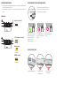
IP68
hh
DC24V
ACHTUNG
VARDAflex LED-Strip darf nicht hängend montiert werden!
MONTAGE LED-STRIP:
HANDHABUNG:
300 mm
Lichtaustrittsfläche Lichtaustrittsfläche
Lichtaustrittsfläche
Lichtaustrittsfläche
Lichtaustrittsfläche
ø 300 mm

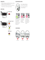
ABMESSUNGEN:
CCT | Intelligence ("3-adrig")
RGB ("4-adrig")
RGBW ("5-adrig")
2 x 0,823 mm²
3 x 0,823 mm²
1 x 0,518 mm²
3 x 0,326 mm²
1 x 0,518 mm²
4 x 0,326 mm²
1.
Das Entfernen des Wassertopp erhöht die Gefahr des Endringen von Wasser/
Feuchtigkeit in das Produkt, und die Garantie erlischt.
2. Bei Unterwasseranwendung muss der Wasserstopp oberhalb der Wasser-
linie verbaut werden, und darf nicht Untergetaucht werden.
WASSERSTOPP:
einfarbig ("2-adrig")
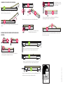
PROFILÜBERGÄNGE:
Winkelversatz Höhenversatz Seitenversatz
Achten Sie darauf einen Abstand von
5 mm an den Stoßstellen einzuhalten,
um die Längenausdehnung ausrei-
chend zu berücksichtigen.
Der Schraubenkopf
darf nicht über die
Montagelinie
drüber hinausragen.
Verschrauben Sie das Profil
mit dem Montageunter-
grund und stellen Sie
sicher, dass die Schraube
bündig oder tiefer als die
Montagelinie liegt.
INSTALLATION IM ALUPROFIL:
Die Schraube muss
gerade eingeschraubt
werden damit Sie nicht
über die Montagelinie
hinausragt.

SaunaSVQ_BA_S76023_05/2022
Carl-Zeiss-Str. 15
28857 Syke
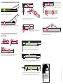
Es ist verboten, eine verschweißte Einspeisung mit Gewalt ins
Profil zu setzen und damit das Band zu deformieren.
Die Zuleitung darf mit keiner mechanischen
Belastung (auf Zug) verbaut werden.
Ziehen
Der Montageabstand einer SL/SR ausgeführten verschweißten
Einspeisung zur Profilabschlusskante darf nicht <10 mm sein.
Der LED-Strip ist aus einer Installationsrichtung zu verarbeiten, um einen
Materialüberschuss zu verhindern.
Der Installationswinkel muss kleiner als 15° sein, während das
Band per Hand in das Profil gedrückt wird.
Der Installationswinkel darf nicht größer als 15° sein, während das
Band per Hand in das Profil gedrückt wird.
INSTALLATIONSRADIEN BEIM EINSETZEN IN ALUPROFILE:
10-20 mm 10-20 mm
10-20 mm 10-20 mm
10-20 mm 10-20 mm
Die Einspeisung SU sowie die Endkappe mit einem Abstand von
10-20 mm von der Abschlusskante des Aluprofils installieren.
Einspeisung ST sowie verschweißte Endkappe mit einem Abstand von
10-20 mm mit den Abschlusskanten des Aluprofils zu installieren.
Die Einspeisung SL/SR sowie die Endkappe mit einem Abstand von
10-20 mm von der Abschlusskante des Aluprofils installieren.
Der Montageabstand einer SU
ausgeführten verschweißten Ein-
speisung zur Profilabschluss-
kante darf nicht <10 mm sein.
Es ist verboten, die Leitung mit übermäßiger
Kraft stark abzuknicken.
Ziehen
INSTALLATIONSABSTÄNDE FÜR VERSCHWEISSTE
EINSPEISUNGEN:
Ziehen

power supply 24 V power supply with
constant voltage output
power/m 6 W
current strength/m 0.25 A
quantity LED/m 108
LED spacing 9.26 mm
dimension of segments
55.56 mm, 6 LEDs
length Maximum length per connection
10 meters
dimensions 55.56* x 16 x 17 mm
bending diameter min. 300 mm
temperature range -45° C to +90° C
processing temperature +10° C to +90° C
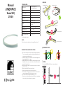
Manual
Sauna SVQ
2700 K
IMPORTANT INSTALLATION INSTRUCTIONS:
1. Be sure to have a professional electrician complete installation.
There is no warranty coverage for any lights installed without ob-
serving european safety directives.
2. Switch off voltage prior to installation. Ensure that voltage cannot
be accidentally switched on again.
3. VARDAFLEX LED strips is suitability for direct mounting on normal
flammable surfaces, e. g. on wood and wood-based materials with
more than 2 mm thickness.
4. Before turning the power on, check all connections for correctness
and short-circuit.
5. Never operate the LED strips when rolled up.
6. Cut the strips exactly at the specified severing lines.
7. Please make sure that an appropriate flex cross-section for the
connection between LED strip and controller is used.
8. Do not exceed the operating temperature of +90° C.
9. Please do not carry out any repairs yourself. Failure to comply may
lead to voiding of the manufacturer's guarantee.
TECHNICAL DATA:
* Section length | module
NOTICE:
This product contains a light source of energy efficiency class: F.
IP68
hh
DC24V
CAUTION:
Do not install VARDAflex LED strips in a suspended way!
MOUNTING LED-STRIP:
HANDLING:
300 mm
light emitting surface light emitting surface
light emitting surface
light emitting surface
light emitting surface
ø 300 mm

DIMENSION:
CCT | Intelligence ("3-wires")
RGB ("4-wires")
RGBW ("5-wires")
2 x 0,823 mm²
3 x 0,823 mm²
1 x 0,518 mm²
3 x 0,326 mm²
1 x 0,518 mm²
4 x 0,326 mm²
1. The removal of anti-wicking ferrule will increase the risk of water ingression
and void the warranty out of it.
2. For Underwater application, do not immerse anti-wicking ferrule in the
water.
ANTI-WICKING FERRULE:
singlecolor ("2-wires")
PROFILE TRANSITIONS:
angular misalignment parallel vertical
misalignment
parallel horizontal
misalignment
Please reserve at least 5 mm for pro-
file jointing to enable enough space
for contraction and expansion.
Screw head above to
the base of aluminum
profile.
Install the screw into po-
sition and ensure the
screw head is flush or
lower the base of
aluminum profile.
INSTALLATION IN THE ALUMINUM PROFILE:
Gradient installing of
screw.

SaunaSVQ_BA_S76023_05/2022
Carl-Zeiss-Str. 15
28857 Syke
It is forbidden to force the injection-moulded end to fit into the
mounting profile and make light deformation.
Mechanical stress on front connector cable shall be avoided.
PULL
The space between injection-moulded infeeder SL/SR/SU and
mounting profile less than 10 mm is forbidden.
Install the light in one direction, no matter what kind of connector used.
Don’t let it choke in middle.
Installing angle should be less than 15 degree when pressing the
light to the aluminum profile by hand.
The circuit board could be damaged if installing angle larger than 15
degree.
BENDING IN THE PROCESS OF INSTALLATION:
10-20 mm 10-20 mm
10-20 mm 10-20 mm
10-20 mm 10-20 mm
Keep 10~20 mm distance from the injection-moulded infeeder
SU as well as the end cap to the edge of aluminum profile.
Keep 10~20 mm distance from the injection-moulded infeeder ST as
well as the end cap to the edge of aluminum profile.
Keep 10~20 mm distance from the injection-moulded infeeder
SL/SR as well as the end cap to the edge of aluminum profile.
The space between connector
and mounting profile less than
10 mm is forbidden.
It is forbidden to curl or pull the front con-
nector cable with excessive force.
PULL
DISTANCE FOR INSTALATION OF INJECTION-MOULDED
INFEEDER:
PULL
-
 1
1
-
 2
2
-
 3
3
-
 4
4
-
 5
5
-
 6
6


in anderen Sprachen
- English: RUTEC 2700K User manual
Andere Dokumente
-
Micro Motion Coriolis Sensoren T-Serie Durchfluss- und Dichtesensoren Installationsanleitung
-
-
-
-
PROLED L65XT00 Benutzerhandbuch
-
Emerson Micro Motion Bedienungsanleitung
-
-
 PROLED L372D40 Benutzerhandbuch
-
-
