MasterCool LEGEND SERIES™ R1234yf & R134a REFRIGERANT ANALYZER Bedienungsanleitung
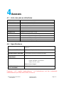
- Typ
- Bedienungsanleitung

456 Creamery Way, Exton, PA 19341, USA
Phone: +1 610.524.8800 • Fax: +1 610.524.8807 • Email: info@refrigerantid.com
www.refrigerantid.com
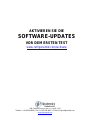
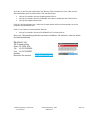
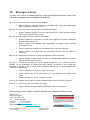
ACTIVATE
SOFTWARE UPDATES
BEFORE FIRST TEST
www.refrigerantid.com/activate

Manual Part Number:
5-06-7000-80-0
Manual File:
012476 Rev. A
Page II

Manual Part Number:
5-06-7000-80-0
Manual File:
012476 Rev. A
Page III
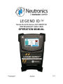
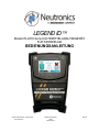
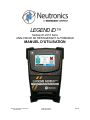
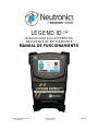
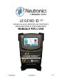
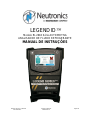
LEGEND ID
Model RI-2018 Series AUTOMOTIVE
REFRIGERANT ANALYZER
OPERATION MANUAL

Manual Part Number:
5-06-7000-80-0
Manual File:
012476 Rev. A
Page IV
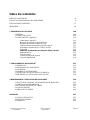
Table of Contents
TABLE OF CONTENTS IV
FOR YOUR SAFETY/ANALYZER WARNINGS V
GENERAL CAUTIONS VI
WELCOME VII
1 INTRODUCTION AND OVERVIEW 1-08
1 GENERAL 1-08
1.1 FEATURES 1-09
1.2 Legend ID™ COMPONENTS 1-10
Legend ID™ Base Unit 1-10
Legend R-1234yf Sample Hose 1-10
Legend R-134a Sample Hose 1-11
Legend Sample Hose Extensions 1-11
R-1234yf and R-134a Low Side Couplers 1-11
USB Cord 1-12
R-1234yf and R-134a Tank Adapter Fittings 1-12
AC Power Adapter 1-13
Control Panel 1-13
Back Panel Connections 1-14
Hard Shell Storage/Carrying Case 1-14
2 LEGEND ID
TM
OPERATION 2-15
2.1 FIRST USE 2-15
2.2 POWER ON THE ANALYZER 2-15
2.3 CALIBRATION 2-16
2.4 TESTING THE REFRIGERANT 2-17
2.5 VIEWING THE TEST RESULTS 2-17
2.6 UNDERSTANDING THE TEST RESULTS 2-18
3 MAINTENANCE & TROUBLESHOOTING 3-20
3.1 REPLACING THE SAMPLE HOSE ASSEMBLY 3-20
3.2 INFORMATION SCREENS 3-20
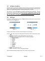
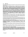
3.3 SOFTWARE UPDATES 3-21
3.4 SETTINGS 3-21
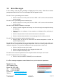
3.5 ERROR MESSAGES 3-22
APPENDICES 4-23
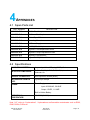
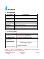
4.1 SPARE PARTS LIST 4-23
4.2 SPECIFICATIONS 4-23
4.3 WARRANTY 4-24

Manual Part Number:
5-06-7000-80-0
Manual File:
012476 Rev. A
Page V
For Your Safety:
PLEASE READ THIS MANUAL IN ITS ENTIRETY BEFORE ATTEMPTING
INSTALLATION OR OPERATION! Attempting to operate this tool without fully
understanding its features and functions may result in unsafe conditions.
Analyzer Warnings
o REFRIGERANT BLEND WARNING: Operate this unit with vehicles or
cylinders marked to contain R-1234yf, R-134a or R-12 refrigerant. Cross-
contamination with other refrigerant types causes severe damage to the
A/C system, to service tools, and equipment. Do NOT attempt to adapt the
unit for another refrigerant. Do NOT mix refrigerant types in a system or in
the same container.
o SAMPLE HOSE WARNING: Replace the sample hose AS SOON AS
LIQUID, OIL OR RED SPOTS (DISCOLORATION) BEGIN TO APPEAR
ON THE INSIDE DIAMETER OF THE SAMPLE HOSE OR WHITE FILTER
ELEMENT. Failure to properly maintain and replace the sample hose will
result in severe damage or inaccurate results.
o FLAMMABILITY WARNING: Some vehicles may contain flammable
refrigerants such as hydrocarbons. R-1234yf is considered a flammable
substance. Failure to follow the manual can result in serious injury or
death. Less than 2 grams of refrigerant are vented with each sample. This
analyzer is designed with sealed heat sources and without sparking
components.
o SAMPLE INPUT WARNING: DO NOT attempt to introduce liquid or
samples heavily laden with oil into the Low Side sampling hose
configuration. Damage caused to the instrument due to the use of the
wrong hose configuration on the wrong port will void the warranty!
o BATTERY CHARGING WARNING: When charging the internal battery with
the supplied power supply, the power supply may become warm. If the
power supply becomes warm, unplug the cord immediately! When
charging multiple analyzers, allow the charger to cool between each
battery.
o AIR SENSOR WARNING: The air detection sensor is a chemical fuel cell
sensor that will eventually expire. The user must return the unit to an
approved vendor in order to replace the air detection sensor whenever the
instrument indicates as such. Failure to replace the air detection sensor will
result in non-functionality of the instrument.
o
POWER SOURCE WARNING: Connection to power sources greater than
13VDC could cause “out of warranty” damage.
o OPPERATIONAL WARNING: If the equipment is used in a manner not
specified by the manufacturer, the protection by the equipment may be
impaired.

Manual Part Number:
5-06-7000-80-0
Manual File:
012476 Rev. A
Page VI
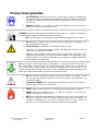
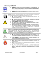
General Cautions
ALWAYS wear eye and skin protection when working with refrigerants.
Escaping refrigerant vapors will present a freezing danger. Do NOT direct
refrigerant escaping from the sample hose toward exposed skin or toward
the face.
ALWAYS turn the compressor or automobile engine OFF before connecting
the instrument to an air conditioning system.
ALWAYS inspect the sample hose before each use. Replace the hose if it appears
cracked, frayed, obstructed or fouled with oil.
DO NOT direct refrigerant vapors venting from hoses towards the skin.
DO NOT disassemble the instrument. There are no serviceable components
internal to the instrument and disassembly will void the warranty.
ALWAYS place the analyzer on a flat and sturdy surface.
To reduce the risk of electrical shock, do NOT disassemble the instrument;
do not use the instrument in wet or damp areas.
Some systems may contain hydrocarbons or flammable refrigerants. This
analyzer is designed with sealed heat sources and without sparking
components. Ensure adequate ventilation and always take proper
precautions when working with refrigerants.
DO NOT breathe refrigerant and lubricant vapor or mist. Exposure may irritate eyes,
nose, and throat. Use recycling equipment certified to meet the requirements of SAE
J2788, J2843, J3030 or J2851 to remove refrigerant from the A/C system. If accidental
system discharge occurs, immediately ventilate the work area. There must be
adequate ventilation in the vehicle servicing area.
DO NOT utilize any hose(s) other than those supplied with the instrument.
The use of other hose types will introduce errors into the refrigerant analysis
and instrument calibration.
ALWAYS verify that the refrigerant, tested from the Low Side, does not
contain or will not emit heavy loads of oil or liquid.
NEVER admit any sample into the instrument at pressures in excess of 500
psig.
NEVER obstruct the air intake, sample exhaust or case vent ports of the
instrument during use.
DO NOT utilize the coupler supplied on the service end of the R-134a or R-
1234yf Sample Hoses for any application other than with the instrument. The
coupler supplied is a modified version that does not contain a check valve
and is not suitable for any other refrigerant application.

Manual Part Number:
5-06-7000-80-0
Manual File:
012476 Rev. A
Page VII
WELCOME
Thank you for purchasing the LEGEND ID
TM
Refrigerant Analyzer.
The Legend ID™ Refrigerant Analyzer is designed for use independently or in conjunction with an
SAE J2843 or J3030 approved A/C Service Machine to determine the purity of gaseous R-134a or R-
1234yf refrigerant. We recommend that all personnel who use this instrument read this manual to
become more familiar with its proper operation.
For further information regarding the application, operation or spare parts, please contact the
Neutronics Inc. Customer Service Department. If you have questions or comments, we would like to
hear from you.
Neutronics Inc.
456 Creamery Way
Exton, PA 19341, USA
Tel: +1 610.524.8800
Fax: +1 610.524.8807
Visit us: www.refrigerantid.com
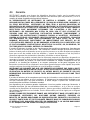
Copyright ©2018 Neutronics Inc.
This work is protected under Title 17 of the US Code and is the sole property of Neutronics Inc. No part of this
document may be copied or otherwise reproduced, or stored in any electronic information retrieval system, except as
specifically permitted under US copyright law, without the prior written consent of Neutronics Inc.

Manual Part Number:
5-06-7000-80-0
Manual File:
012476 Rev. A
Page 1-8
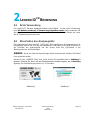
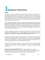
1 INTRODUCTION AND OVERVIEW
General
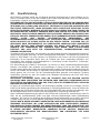
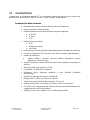
Contamination of refrigerants either in storage cylinders or vehicle air conditioning systems can lead
to component corrosion, elevated head pressures and system failures when utilized by unsuspecting
technicians. The ability of the technician to determine refrigerant type and purity is severely
hampered by the presence of air when attempting to utilize temperature-pressure relations. The
development of various substitute refrigerants further complicates the ability of a technician to identify
refrigerant purity based upon temperature-pressure relationships.
The Neutronics Legend ID™ Refrigerant Analyzer will provide a fast, easy and accurate means to
determine refrigerant purity in refrigerant storage cylinders or directly in vehicle air conditioning
systems. The instrument utilizes non-dispersive infrared (NDIR) technology to determine the weight
concentration of R-1234yf or R-134a refrigerant. Acceptable refrigerant purity as it relates to this
instrument, has been defined by the SAE as a refrigerant mixture that contains 98.0%, or greater of
R-1234yf or R-134a, by weight.
The instrument is supplied complete with an R-1234yf sample hose, an R-134a sample hose (R-12
coupler sold separately), a 100- 240 VAC power transformer, built in Lithium battery, thermal printer,
and all required plumbing housed within a rugged, portable, storage case.
Sample gas is admitted into the instrument through the supplied sample hose and presented to the
sensing device. The instrument provides the user with a digital display of refrigerant purity. The
instrument only considers the weights of the refrigerant and contaminates in the total mixture. Air is
measured, and displayed, separately. Other contents such as refrigerant oil and dye are not
considered contaminants.
The instrument interfaces with the user via a full color graphic LCD, audio indications and soft key
command buttons. Alarm indications are provided to alert of instrument fault conditions or
contaminated refrigerant presence.
Required SAE Statement (SAE J2912): "If the refrigerant being tested is identified as
contaminated (i.e., less than 98% pure R-1234yf or HFC-134a), any visual percentages displayed
of HFC-134a (R-134a) and/or HFO-1234yf (R-1234yf), outside the design certified value is
informational and may not be accurate"

Manual Part Number:
5-06-7000-80-0
Manual File:
012476 Rev. A
Page 1-9
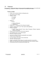
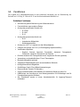
1.1 Features
The Legend ID™ Refrigerant Analyzer is the most precise handheld instrument ever manufactured
for determining the purity of R-1234yf, R-134a and R-12 in the automotive market.
Features Include:
Quickly and accurately determines refrigerant purity
Advanced ergonomic design
Displays % purity:
o R-1234yf
o R-134a
o R-12
Displays %:
o R-22
o Unknown Refrigerant
o Hydrocarbons
Displays AIR % independent of the refrigerant sampled
Capable of analyzing R-12 (1/4” Flare coupler sold separately)
Multiple Languages:
o English, German, Spanish, French, Italian, Portuguese, Chinese, Japanese,
Korean and Russian
Easily prints test results with built-in printer (optional)
Uses Standard 2.25” (57 mm) thermal paper
Bluetooth compatible (optional)
Improved oil resistance with user replaceable hose assembly
Fender friendly resting surface
Full Color Graphic LCD with on-screen instructions
Ultra-fast 70 second test time
Internal, rechargeable Lithium battery for cordless operation in any location
USB Port for connection to the AC Service Machine & remote software updates
All accessories stored in hard shell carry/storage case

Manual Part Number:
5-06-7000-80-0
Manual File:
012476 Rev. A
Page 1-10
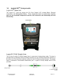
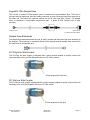
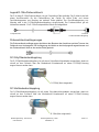
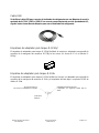
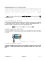
Analyzer End
Service End
R-1234yf Low Side
Coupler
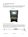
1.2 Legend ID
TM
Components
Legend ID
TM
Base Unit
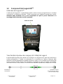
The Legend ID™ base unit houses the Full Color Graphic LCD, Infrared Bench, Electrical
Connections, and Rechargeable Battery. These components require no maintenance, therefore
there are no serviceable components internal to the instrument, and disassembly will void
the warranty.
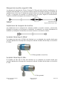
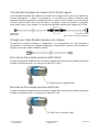
Legend R-1234yf Sample Hose
The 6.5-foot (2 meter) R-1234yf Sample Hose is constructed of polyurethane ether. The hose is
provided with an instrument inlet port mating connector on one end and a brass flow restrictor on
the other end. The brass flow restrictor screws into the R-1234yf Low Side Coupler. The sample
hose is considered a consumable maintenance part. A spare R-1234yf Sample Hose is also
provided.
Control Panel

Manual Part Number:
5-06-7000-80-0
Manual File:
012476 Rev. A
Page 1-11
Legend R-134a Sample Hose
The 6.5-foot (2 meter) R-134a Sample Hose is constructed of polyurethane ether. The hose is
provided with an instrument inlet port mating connector on one end and a brass flow restrictor on
the other end. The brass flow restrictor screws into the R-134a Low Side Coupler. The sample
hose is considered a consumable maintenance part. A spare R-134a Sample Hose is also
provided.
Sample Hose Extensions
The sample hose extensions allow the user to easily connect and disconnect the hose assembly to
the analyzer. The extension is connected directly to the analyzer and the sample hose connects to
the male feral on the opposite end.
R-1234yf Low Side Coupler
The R-1234yf low side coupler is designed with a quick connect adapter to quickly connect the
hose assembly to the Low Side Schrader valve on a R-1234yf vehicle.
R-1234yf (engraved in fine text)
R-134a Low Side Coupler
The R-134a low side coupler is designed with a quick connect adapter to quickly connect the hose
assembly to the Low Side Schrader valve on a R-134a vehicle.
R-134a (engraved in fine text)
Analyzer End
Service End
R-134a Low Side Coupler

Manual Part Number:
5-06-7000-80-0
Manual File:
012476 Rev. A
Page 1-12
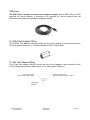
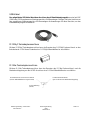
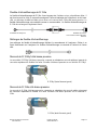
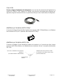
USB Cord
The USB Cord is provided to connect the refrigerant analyzer with an SAE J2843 or J3030
approved A/C Service Machine. If connecting to an approved A/C service machine follow the
instructions on this machine to operate the refrigerant analyzer.
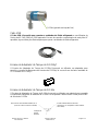
R-1234yf Tank Adapter Fitting
The R-1234yf Tank Adapter Fitting will provide the user with an adapter to allow connection of the
R-1234yf Sample Hose to the ½” LH Acme threads on the R-1234yf cylinder.
R-134a Tank Adapter Fitting
The R-134a Tank Adapter Fitting will provide the user with an adapter to allow connection of the
R-134a Sample Hose and Low Side Coupler to a R-134a cylinder ACME port.
R-134a Low Side Stub
(Fits into R-134a Low-Side Coupler)
½” RH Acme Thread
(Threads onto Cylinder Stub)
O-Ring Seal
(Internal)

Manual Part Number:
5-06-7000-80-0
Manual File:
012476 Rev. A
Page 1-13
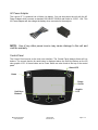
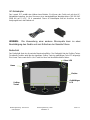
AC Power Adapter
The Legend ID™ is powered via a Lithium Ion battery. You can also power the unit with the AC
Power Adapter which converts a standard 100-240VAC 50/60Hz wall outlet to 12VDC, 1.6A. This
AC Power Adapter will also charge the battery when connected to the analyzer.
NOTE: Use of any other power source may cause damage to the unit and
void the warranty.
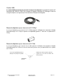
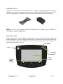
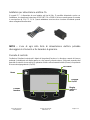
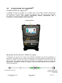
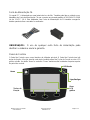
Control Panel
The Control Panel serves as the main user interface. The Control Panel features three soft key
buttons. The current function for each button is displayed above the Soft Key Buttons on the full
color graphic LCD. A Home button and a Power button are also found at the top of the control
panel.
Home
Power
On/Of
f
Soft Keys
Buttons
Graphic
LCD
Green LED

Manual Part Number:
5-06-7000-80-0
Manual File:
012476 Rev. A
Page 1-14
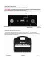
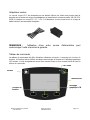
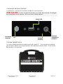
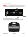
Back Panel Connections
The connections located on the back panel are illustrated below.
CAUTION:
The sample outlet port should never be obstructed. Keep the sample outlet port
free and clear at all times. Do not operate near open flame.
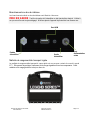
Hard-Shell Storage/Carrying Case
The hard-shell storage/carrying case is custom fit to the Legend ID™. It provides rugged
protection for the instrument, as well as convenient storage for all components. The enclosure is
general purpose and is not watertight.
Sample Inlet
Sample Outlet
Factory
power port
USB Port

Manual Part Number:
5-06-7000-80-0
Manual File:
012476 Rev. A
Page 2-15
2 LEGEND ID
TM
OPERATION
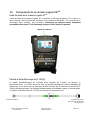
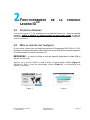
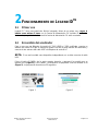
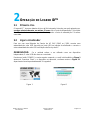
2.1 First Use
The Legend ID™ has a built in Lithium Ion battery. Prior to first use charge the battery for
a minimum of 2 hours with the included AC Power Supply. The analyzer will function and
charge the battery when the AC Power Supply is connected.
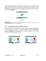
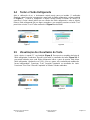
2.2 Power On the Analyzer
For use with an SAE J2843 or J3030 certified AC Service Machine, connect one end of the
provided USB cable to the USB port on the back of the analyzer and connect the other end
of the USB cable to the AC Service Machine.
NOTE:
If the unit is used as an independent device the USB cable should not be
connected.
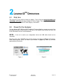
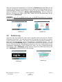
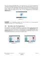
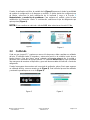
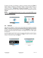
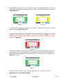
Press the upper right, ‘POWER’ button and the splash screen shown in (Figure 1) will appear.
Press ‘Next’ and the device will warm up as shown in (Figure 2). Warm up will take
approximately 30 seconds.
Figure 1
Figure 2

Manual Part Number:
5-06-7000-80-0
Manual File:
012476 Rev. A
Page 2-16
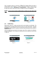
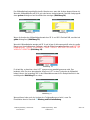
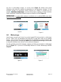
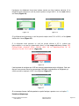
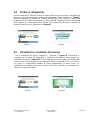
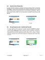
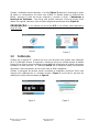
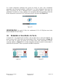
Once the analyzer warms up, the screen in (Figure 3) will appear offering the option to
change settings or start an analysis. If you wish to adjust factory ‘Settings’, select the left soft
key and refer to section 3 Maintenance & Troubleshooting. To begin an analysis, select
the right ‘Start’ soft key. Next select the type of refrigerant you wish to test (Figure 4).
NOTE:
If you are going to analyze a R-12 vehicle or cylinder you must select R-134a
mode.
2.3 Calibration
Each time the Legend ID™ begins a new test cycle it must complete an air calibration. The
calibration takes 30 seconds and pulls fresh air into the unit via an internal pump. This fresh
air purges any excess refrigerant from the unit and ensures accurate test results. Calibration
REQUIRES a sample hose be connected to the device and disconnected from the vehicle or
refrigerant source.
Once the sample hose is connected to the analyzer, press ‘Start’ to begin an air calibration,
as shown in (Figure 5). This will begin the calibration process and display the screen shown
in (Figure 6).
Figure 3
Figure 6
Figure 5
Figure 4

Manual Part Number:
5-06-7000-80-0
Manual File:
012476 Rev. A
Page 2-17
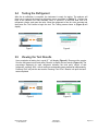
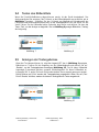
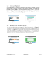
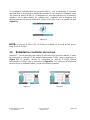
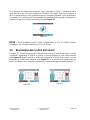
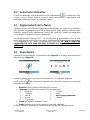
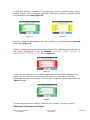
2.4 Testing the Refrigerant
After the air calibration is complete, the instrument is ready for testing. The analyzer will
direct you to connect the hose to a refrigerant source as shown in (Figure 7). Connect the
hose to the vehicles Low Side Schrader valve, or connect it to the Low Side Port on a
refrigerant cylinder, and open the valve. Allow the refrigerant to flow for a few seconds and
then press the ‘Test’ button to begin the test. The Testing screen shown in (Figure 8) will
display.
2.5 Viewing the Test Results
Upon completion of testing, the Legend ID™ will display (Figure 9). Disconnect the coupler
from the refrigerant source and select ‘Results’ to display the test results (Figure 10). The
percentage displayed for each refrigerant indicates the total purity weight of that
refrigerant, equaling 100%, with air and non-condensable gases measured independently.
Pressing ‘Print’ will print the test results. Pressing ‘Print Prior 5 Results’ will print the last 5
tests completed.
Fi
g
ure 8
Fi
g
ure 9
Fi
g
ure 10
Fi
g
ure 7

Manual Part Number:
5-06-7000-80-0
Manual File:
012476 Rev. A
Page 2-18
If the refrigerant analyzed is 98.0% pure or better, the refrigerant is deemed suitable for
standard recovery and reuse. Should the refrigerant be less than 98.0% pure, the refrigerant
is not suitable for standard recovery and should not be reused. In either case, verify the hose
is disconnected from the refrigerant source and press ‘Exit’ to return to the main screen
(Figure 11).
NOTE:
In R-134a mode, R-12 and R-1234yf are combined into one reading referred to as
“R-12/ R-1234yf.”
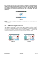
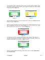
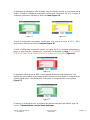
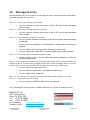
2.6 Understanding Test Results
The Legend ID™ is designed to analyze the base gas it is calibrated for. When testing R-
134a vehicle, R-134a should be select as shown on (Figure 12). Conversely when testing a
R-1234yf vehicle, R-1234yf should be selected as shown in (Figure 13). If the wrong base
refrigerant is selected the analyzer will fail the test and produce inaccurate results.
Figure 11
Fi
g
ure 12
Fi
g
ure 13

Manual Part Number:
5-06-7000-80-0
Manual File:
012476 Rev. A
Page 2-19
The refrigerant analyzer is designed to provide visual cues after analysis is complete. When
the refrigerant sampled is found to be 98% pure or greater the analyzer will display a Green
background indicator (Figure 14).
When the sampled refrigerant is found to be between 95% - 98% pure a Yellow background
indicator will appear (Figure 15).
When the sampled refrigerant is found to be less than 95%, presents hydrocarbons or a has
large contamination the screen will illuminate Red and CAUTION SHOULD BE TAKEN
WHEN HANDLING THIS VEHICLE OR CYLINDER (Figure 16).
It is important to note AIR is measured independently of the refrigerant. This means you
could have a percentage of AIR present in a sample or refrigerant that totals or equals 100%
refrigerant. An example of this is present in (Figure 17) below.
If an error message appears at all during or after analysis. Refer to section
3
Maintenance
and Troubleshooting.
Figure 14
Figure 16
Figure 17
Fi
g
ure 15

Manual Part Number:
5-06-7000-80-0
Manual File:
012476 Rev. A
Page 3-20
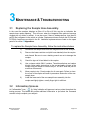
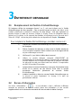
3 MAINTENANCE & TROUBLESHOOTING
3.1 Replacing the Sample Hose Assembly.
In the event the analyzer displays an Error #3 or Error #5 this may be an indication the
sample hose needs replacing. This will occur when the integrated flow restrictor becomes
clogged with oil, debris or sealant. It can also occur if there is inadequate flow, less than 30
psig (2 Bar) refrigerant in the vehicle or cylinder. Replacement hoses for both the R-134a and
R-1234yf couplers are provided in the kit. Additional replacements are listed on the spare
parts list in section
4
Appendices.
To replace the Sample Hose Assembly, follow the instructions below:
1) Disconnect the sample hose from the refrigerant source and Analyzer
2) Remove the brass restrictor end (with hose attached) from the coupler
and discard. Be sure to use a backing wrench as not to damage the
coupler.
3) Check for signs of oil and debris in the coupler.
4) Use a cleaner which ONLY contains, Tetrachloroethylene and carbon
dioxide, follow safety instructions on the can and spray all parts of the
coupler with the cleaner to remove any oil. DO NOT soak the part for
more than 60 seconds.
5) Allow coupler to dry. Check coupler for oil once again. Failure to clean
the oil out of the coupler will result in premature obstruction of the new
sample hose.
6) Install the brass end of the new sample hose assembly into the
coupler and lightly tighten, usually finger tight is sufficient.
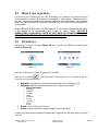
3.2 Information Screens
An
“Information” icon
or ‘Help’ indication will appear at various points throughout the
testing process. This button will provide additional information or tips about the command
screens to help complete your analysis.
Seite wird geladen ...
Seite wird geladen ...
Seite wird geladen ...
Seite wird geladen ...
Seite wird geladen ...
Seite wird geladen ...
Seite wird geladen ...
Seite wird geladen ...
Seite wird geladen ...
Seite wird geladen ...
Seite wird geladen ...
Seite wird geladen ...
Seite wird geladen ...
Seite wird geladen ...
Seite wird geladen ...
Seite wird geladen ...
Seite wird geladen ...
Seite wird geladen ...
Seite wird geladen ...
Seite wird geladen ...
Seite wird geladen ...
Seite wird geladen ...
Seite wird geladen ...
Seite wird geladen ...
Seite wird geladen ...
Seite wird geladen ...
Seite wird geladen ...
Seite wird geladen ...
Seite wird geladen ...
Seite wird geladen ...
Seite wird geladen ...
Seite wird geladen ...
Seite wird geladen ...
Seite wird geladen ...
Seite wird geladen ...
Seite wird geladen ...
Seite wird geladen ...
Seite wird geladen ...
Seite wird geladen ...
Seite wird geladen ...
Seite wird geladen ...
Seite wird geladen ...
Seite wird geladen ...
Seite wird geladen ...
Seite wird geladen ...
Seite wird geladen ...
Seite wird geladen ...
Seite wird geladen ...
Seite wird geladen ...
Seite wird geladen ...
Seite wird geladen ...
Seite wird geladen ...
Seite wird geladen ...
Seite wird geladen ...
Seite wird geladen ...
Seite wird geladen ...
Seite wird geladen ...
Seite wird geladen ...
Seite wird geladen ...
Seite wird geladen ...
Seite wird geladen ...
Seite wird geladen ...
Seite wird geladen ...
Seite wird geladen ...
Seite wird geladen ...
Seite wird geladen ...
Seite wird geladen ...
Seite wird geladen ...
Seite wird geladen ...
Seite wird geladen ...
Seite wird geladen ...
Seite wird geladen ...
Seite wird geladen ...
Seite wird geladen ...
Seite wird geladen ...
Seite wird geladen ...
Seite wird geladen ...
Seite wird geladen ...
Seite wird geladen ...
Seite wird geladen ...
Seite wird geladen ...
Seite wird geladen ...
Seite wird geladen ...
Seite wird geladen ...
Seite wird geladen ...
Seite wird geladen ...
Seite wird geladen ...
Seite wird geladen ...
Seite wird geladen ...
Seite wird geladen ...
Seite wird geladen ...
Seite wird geladen ...
Seite wird geladen ...
Seite wird geladen ...
Seite wird geladen ...
Seite wird geladen ...
Seite wird geladen ...
Seite wird geladen ...
Seite wird geladen ...
Seite wird geladen ...
Seite wird geladen ...
Seite wird geladen ...
Seite wird geladen ...
Seite wird geladen ...
Seite wird geladen ...
Seite wird geladen ...
Seite wird geladen ...
Seite wird geladen ...
Seite wird geladen ...
Seite wird geladen ...
Seite wird geladen ...
Seite wird geladen ...
Seite wird geladen ...
Seite wird geladen ...
Seite wird geladen ...
Seite wird geladen ...
Seite wird geladen ...
Seite wird geladen ...
Seite wird geladen ...
Seite wird geladen ...
Seite wird geladen ...
Seite wird geladen ...
Seite wird geladen ...
Seite wird geladen ...
Seite wird geladen ...
Seite wird geladen ...
-
 1
1
-
 2
2
-
 3
3
-
 4
4
-
 5
5
-
 6
6
-
 7
7
-
 8
8
-
 9
9
-
 10
10
-
 11
11
-
 12
12
-
 13
13
-
 14
14
-
 15
15
-
 16
16
-
 17
17
-
 18
18
-
 19
19
-
 20
20
-
 21
21
-
 22
22
-
 23
23
-
 24
24
-
 25
25
-
 26
26
-
 27
27
-
 28
28
-
 29
29
-
 30
30
-
 31
31
-
 32
32
-
 33
33
-
 34
34
-
 35
35
-
 36
36
-
 37
37
-
 38
38
-
 39
39
-
 40
40
-
 41
41
-
 42
42
-
 43
43
-
 44
44
-
 45
45
-
 46
46
-
 47
47
-
 48
48
-
 49
49
-
 50
50
-
 51
51
-
 52
52
-
 53
53
-
 54
54
-
 55
55
-
 56
56
-
 57
57
-
 58
58
-
 59
59
-
 60
60
-
 61
61
-
 62
62
-
 63
63
-
 64
64
-
 65
65
-
 66
66
-
 67
67
-
 68
68
-
 69
69
-
 70
70
-
 71
71
-
 72
72
-
 73
73
-
 74
74
-
 75
75
-
 76
76
-
 77
77
-
 78
78
-
 79
79
-
 80
80
-
 81
81
-
 82
82
-
 83
83
-
 84
84
-
 85
85
-
 86
86
-
 87
87
-
 88
88
-
 89
89
-
 90
90
-
 91
91
-
 92
92
-
 93
93
-
 94
94
-
 95
95
-
 96
96
-
 97
97
-
 98
98
-
 99
99
-
 100
100
-
 101
101
-
 102
102
-
 103
103
-
 104
104
-
 105
105
-
 106
106
-
 107
107
-
 108
108
-
 109
109
-
 110
110
-
 111
111
-
 112
112
-
 113
113
-
 114
114
-
 115
115
-
 116
116
-
 117
117
-
 118
118
-
 119
119
-
 120
120
-
 121
121
-
 122
122
-
 123
123
-
 124
124
-
 125
125
-
 126
126
-
 127
127
-
 128
128
-
 129
129
-
 130
130
-
 131
131
-
 132
132
-
 133
133
-
 134
134
-
 135
135
-
 136
136
-
 137
137
-
 138
138
-
 139
139
-
 140
140
-
 141
141
-
 142
142
-
 143
143
-
 144
144
-
 145
145
-
 146
146


MasterCool LEGEND SERIES™ R1234yf & R134a REFRIGERANT ANALYZER Bedienungsanleitung
- Typ
- Bedienungsanleitung
in anderen Sprachen
- English: MasterCool LEGEND SERIES™ R1234yf & R134a REFRIGERANT ANALYZER Operating instructions
- français: MasterCool LEGEND SERIES™ R1234yf & R134a REFRIGERANT ANALYZER Mode d'emploi
- español: MasterCool LEGEND SERIES™ R1234yf & R134a REFRIGERANT ANALYZER Instrucciones de operación
- italiano: MasterCool LEGEND SERIES™ R1234yf & R134a REFRIGERANT ANALYZER Istruzioni per l'uso
- português: MasterCool LEGEND SERIES™ R1234yf & R134a REFRIGERANT ANALYZER Instruções de operação
Verwandte Artikel
Andere Dokumente
-
Waeco BMW5000RPA Bedienungsanleitung
-
-
-
Waeco R-134a (Analysis module) Bedienungsanleitung
-
Waeco Waeco ASC 5000 RPA, ASC 5500 RPA Bedienungsanleitung
-
-
Waeco ASC5500G RPA Bedienungsanleitung
-
Waeco VAS 581 001A Bedienungsanleitung
-
Waeco Waeco ASC 5500 G RPA 2020 Bedienungsanleitung
-