
Bedienungsanleitung
Operation Manual
DCC MM
5302
Koppler
Coupler
1. Wichtige Hinweise ...................................... 2
2. Einleitung .................................................... 3
3. Funktionen ................................................. 3
4. Anschluss ................................................... 5
5. Konguration.............................................. 7
6. FehlersucheundAbhilfe ............................ 8
7. TechnischeDaten ...................................... 8
1. Important information ................................. 2
2. Introduction ................................................ 3
3. Functions ................................................... 3
4. Connection ................................................. 5
5. Conguration .............................................. 7
6. Trouble-shooting......................................... 8
7. Technical data ............................................ 8
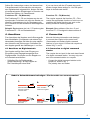
AC
~
DC
=

2
DE EN
1. Wichtige Hinweise
BittelesenSievordererstenAnwendungdes
Produktesbzw.dessenEinbaudieseBedienungs-
anleitungaufmerksamdurch.BewahrenSiediese
auf,sieistTeildesProduktes.
1.1 Sicherheitshinweise
Vorsicht:
FürdieMontagesindWerkzeugenötig.
Stromschlaggefahr!
DieAnschlussdrähteniemalsineineSteckdo-
seeinführen!VerwendetesVersorgungsgerät
(Transformator,Netzteil,Digitalzentrale)regel-
mäßigaufSchädenüberprüfen.BeiSchädenam
Versorgungsgerätdieseskeinesfallsbenutzen!
AlleAnschluss-undMontagearbeitennurbei
abgeschalteterBetriebsspannungdurchführen!
AusschließlichnachVDE/EN-gefertigteModell-
bahntransformatorenverwenden!
Stromquellenunbedingtsoabsichern,dasses
beieinemKurzschlussnichtzumKabelbrand
kommenkann.
1.2 Das Produkt richtig verwenden
DiesesProduktistbestimmt:
- ZumEinbauinModelleisenbahnanlagenund
Dioramen.
- ZumAnschlussaneineDigitalzentrale(Mot.
oderDCC)miteinerAusgangsspannungvon
max.30VamHauptgleisausgangbzw.anden
ViessmannCommanderArt.-Nr.5300.
- ZumBetriebintrockenenRäumen.
JederdarüberhinausgehendeGebrauchgiltals
nichtbestimmungsgemäß.Fürdarausresultieren-
deSchädenhaftetderHerstellernicht.
1.3 Packungsinhalt überprüfen
KontrollierenSiedenLieferumfangaufVollständigkeit:
- KopplerArt.-Nr.5302
- 2Schrauben
- LSB-Kabel28cmArt.-Nr.5390
- Anleitung
1. Important information
Please read this manual completely and attentively
beforeusingtheproductforthersttime.Keepthis
manual. It is part of the product.
1.1 Safety information
Caution:
For installation tools are required.
Electrical hazard!
Neverputtheconnectingwiresintoapower
socket!Regularlyexaminethetransformerfor
damage.Incaseofanydamage,donotusethe
transformer!
Makesurethatthepowersupplyisswitched
owhenyoumountthedeviceandconnectthe
cables!
Only use VDE/EN tested special model train
transformersforthepowersupply!
Thepowersourcesmustbeprotectedto
preventtheriskofburningcables.
1.2 Using the product for its correct
purpose
This product is intended:
- For installation in model train layouts and
dioramas.
- Forconnectiontoadigitalcommandstation(Mot.
orDCC)withanoutputvoltageofmax.30Vat
the main track output resp. for connection to the
ViessmannCommanderitem-No.5300.
- For operation in dry rooms only.
Usingtheproductforanyotherpurposeisnot
approved and is considered incorrect. The
manufacturerisnotresponsibleforanydamage
resultingfromtheimproperuseofthisproduct.
1.3 Checking the package contents
Checkthecontentsofthepackageforcompleteness:
- Coupleritem-No.5302
- 2Screws
- LSB-cable28cmitem-No.5390
- Manual

3
2. Einleitung
DerKopplerstelltüberdenleistungsfähigen
ViessmannSpeedBusdieVerbindungzwischen
Motorola-bzw.DCC-ZentralenunddemViess-
mannCommanderher.Damitlassensichbereits
vorhandeneDigitalzentralenderSystemeMärklin-
MotorolaundDCCalsFahrgeräteoderStellpulte
weiternutzen.ZusätzlichistaufdieseWeisedie
einfacheVerknüpfungzweierCommandermög-
lich.DerGleisausgangderbisherigenZentrale
wirdlediglichundausschließlichandenEingang
desKopplersangeschlossen.DerKopplerhört
aufdieeingehendenSignalederZentrale,berei-
tetdieseInformationenaufundgibtsieüberden
SpeedBusandenCommanderweiter.DerCom-
manderwertetdieseBefehleausundsendetsie
andieAnlage.
Wichtig:Die„alte“ZentraledarfkeineGleisab-
schnittemehrmitStromversorgen,daansonsten
Kurzschlussgefahrbesteht!
FunktionsmodelleohneVerbindungzurAnlage
könnenbetriebenwerden.
DerViessmannSpeedBusermöglichtdenkom-
fortablenAnschlussmitautomatischerAnmeldung
amCommander.
DieinterneSoftwaredesKopplersistüberden
SpeedBusunddenCommanderupdatefähig,so
dassSiediesestetsaufeinemaktuellenStand
haltenkönnen.
Hinweis:DerKoppleristnichtdazugedacht,den
CommandermiteinerZentralezuverbinden,die
inZusammenhangmiteinemPCeinenAutoma-
tikbetriebabarbeitet.Diesistauchnichterforder-
lich,daderCommanderdieFunktioneneinerPC-
SteuerungimPrinzipübernehmenkann.
Hinweis: Einbahnstraße!DerKopplerkann
keineInformationenandiesendendeZentrale
zurückgeben.DiesistüberdasGleisformat
nichtmöglich.
3. Funktionen
DerKopplerlegteineListefürdieFahrbefehle
derLokomotivenundeineweiterefürdieSchalt-
befehlean.DieListederFahrbefehleüberträgt
derKopplerüberdenSpeedBus(LSB)nachdem
ErstellenundanschließendbeijederÄnderung
einesBefehlserneutandenCommander.Eine
permanenteÜbertragungndetnichtstatt.Zusätz-
lichkannderCommanderdieInformationendes
KopplersauchdurcheinAnforderungskommando
beidiesemabfragen.
Schaltbefehlewerdensolangeübertragen,wie
derSchaltbefehlanliegt.EinepermanenteÜber-
tragungndetnichtstatt.
2. Introduction
The coupler provides a connection from Mo-
torola- or DCC command stations to the Viess-
mannCommanderviathepowerfulViessmann
SpeedBus.Itispossibletousealreadyexisting
digitalcommandstationsfurthermoreasthrottleor
panel.Inaddition,theeasylinkingof2Comman-
ders is possible. The track output of the previous
command station has to be connected only and
exclusivelytotheinputofthecoupler.Thecoupler
listenstotheincomingsignalsofthecommand
stationandsendsthesesignalsviatheViess-
mann SpeedBus to the Commander. The Com-
mander interprets the orders and sends them to
the layout.
Caution: The “previous” command station must
notbeconnectedtotracksections–dangerof
short circuit!
Functionalmodelswithoutconnectiontothelay-
out may be controlled directly.
TheViessmannSpeedBusallowsthecomfortable
connectiontotheCommanderwithautocongu-
ration.
Thermwareofthecouplercanbeupdatedvia
SpeedBus and Commander.
Notice: It is not intended to use the coupler to
connect a PC-controlled station to the Comman-
der,whichcontrolsautomaticoperation.
This is not necessary because the Commander
includes the functions of a PC-control.
Notice: One-Way-Street! The coupler cannot
sendinformationbacktothesendingcommand
station.Thetrackformatdoesnotallowtosend
feedback.
3. Functions
The coupler creates one list for the propulsion
commands of the locomotives and another one for
theswitchingorders.Aftercreating,thecoupler
transmits the list of the propulsion commands via
theSpeedBus(LSB)totheCommanderandthen
eachtimewhenaneworderiswrittenintothelist.
The list is not transmitted permanently.
Additionally,theCommandercansendarequest
command to the coupler.
Switchingorderswillbetransmittedaslongasthe
switchingorderisactive.Thelistisnottransmitted
permanently.

4
DieDigitalformateMot.undDCCkönnen„quasi
gleichzeitig“empfangenwerden.Deshalbmuss
derKopplernichtaufeinDigitalformathinkongu-
riertwerden.
DerCommandersperrtkeineLokadressen.So
kannüberdenKopplerjederzeitaufjedeLokauf
demCommanderzugegrienwerden.Dieletzte
Steuerinformationistdadurchimmergültig–
gleichgültigobsievomCommanderoderüber
denKopplervoneineranderenZentralekommt.
Hinweis:Adressendürfen–unabhängigvomDa-
tenformat–nureinmalvergebenwerden.Eine
LokmitderAdresse„3“imMotorola-Formatund
gleichzeitigeineLokmitderAdresse„3“imDCC-
Formatsindnichtzulässig.
Auf beiden Zentralen müssen die Loks im
gleichen Digitalformat und mit gleicher
Fahrstufenzahl angelegt sein.
3.1 DCC
DerKopplerverstehtdieuntenaufgeführtenBe-
fehlefürFahrenundSchaltenimSystemDCC:
Fahren:
- 9999Lokadressen
- 14,28und128Fahrstufen
- FunktionenLichtundF1–F12
- LoksanhaltenüberGeneralCalloderNothalt
durchStromabschaltung
Schalten:
- 1024Weichen-Adressenrot/grün–ein/aus
MehrbegrigeWeichenundSignalewerden
unterstützt.
3.2 Märklin-Motorola
DerKopplerverstehtdieuntenaufgeführtenBe-
fehlefürFahrenundSchaltenimSystemMärklin-
Motorola:
Fahren:
- 80Lokadressen
- 14Fahrstufen
- NothaltdurchStromabschaltung
- FunktionenLichtundF1–F4
- Keinemfx-Erkennung
Schalten:
- 320Weichen-Adressenrot/grün–ein/aus
MehrbegrigeWeichenundSignalewerden
unterstützt.
Hinweis:
DerKopplerunterstütztden27-Fahrstufen-
ModuswederbeiMotorolanochbeiDCC.Auch
derCommanderunterstütztdiesenModusnicht.
The coupler can receive and send orders in Mo-
torola and DCC format simultaneously.
Thereforeitisnotneededtocongurethecoupler
toadigitalformat.
The Commander does not block locomotive ad-
dresses. So you can address each locomotive via
the coupler any time. Therefore the last loco order
isalwaysvalid,nomatterifitcomesfromthe
Commander or via the coupler from another com-
mand station.
Notice:Addressesmustonlybeusedonce–no
matterinwhichdigitalformattheyareused.Aloco
withtheaddress“3”inMotorola-formatandaloco
withtheaddress“3”inDCC-formatatthesame
timearenotallowed.
On both digital command stations the locos
must have the same digital format and the
same number of speed steps.
3.1 DCC
Thecouplerunderstandsthefollowingordersfor
drivingandswitchingintheDCCsystem:
Driving:
- 9999locoaddresses
- 14,28and128speedsteps
- FunctionslightandF1–F12
- Stoplocosviageneralcalloremergencystop
bytrackpowero
Switching:
- 1024turnoutaddressesred/green–on/o
Multiturnoutsandmultiaspectsignalsare
supported.
3.2 Märklin-Motorola
Thecouplerunderstandsthefollowingordersfor
drivingandswitchingintheMärklin-Motorolasys-
tem:
Driving:
- 80locoaddresses
- 14 speed steps
- Emergencystopbytrackpowero
- FunctionslightandF1–F4
- Nomfx-recognition
Switching:
- 320turnoutaddressesred/green–on/o
Multiturnoutsandmultiaspectsignalsare
supported.
Notice:
The coupler does not support the mode 27 speed
steps,neitherinMotorolasystemnorinDCCsystem.
The Commander does not support this mode either.

5
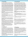
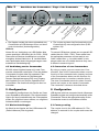
1. 2.
3. 4. 5.
Draht einschiebenDraht umbiegen
Litzen verdrillenKabel abisolieren
Schraube festziehen
Insert wire Bend wire
Twist wires togetherStrip the insulation
from the cable
Tighten the screw
5 mm
SolltenSieLokomotivennutzen,beidenendiese
FahrstufenanzahlimDecoderbzw.dersteuern-
denDigitalzentraleeingestelltist,ändernSiebitte
dieentsprechendenEinstellungeninDecoderund
Zentraleauf28bzw.14Fahrstufenab.
Funktionen F5 – F8 (Motorola):
DieFunktionenF5–F8zurAnsteuerungderent-
sprechendenFunktionenbeimfx-Lokswerdenun-
terstützt.VoraussetzungistdieÜbertragungdie-
serFunktionenaufdernumerischdirektfolgenden
Adresse.
Beispiel:BasisadressederLok:5,Zuordnungder
FunktionenF5–F8zurBasisadresse6.
4. Anschluss
ZumAnschlussdesKopplersandieSteuergeräte
IhrerModellbahn(CommanderundweitereDigi-
talzentralen)beachtenSiebittedieuntenstehen-
denHinweiseundZeichnungen.SchließenSie
denKopplergemäßdenAbbildungen1und2an.
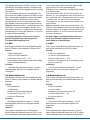
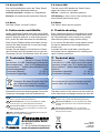
4.1 Anschluss an Digitalzentrale
DerKopplerverfügtübereinenEingangzur
EinspeisungdesHauptgleisausgangseiner
Digitalzentrale.SiekönnenandenKopplernur
eineZentraleanschließen.
- SchließenSiedieDigitalzentrale
gemäßAbbildung1andenKoppleran.
DiePolaritätspieltkeineRolle.
Ifyouuselocoswiththe27speedstepmode,
pleasechangethesesettingsto14or28speed
steps in decoder and station.
Functions F5 – F8 (Motorola):
ThecouplersupportsthefunctionsF5–F8to
controltheappropriatefunctionsofmfx-locoson
condition that these functions are sent on the
directlynumericalfollowingaddress.
Example: Base address of the loco: 5 and
functionsF5–F8assignedtobaseaddress6.
4. Connection
Notethefollowinginformationanddrawings
to connect the coupler to the control units
(Commanderandfurtherdigitalcommand
stations) of your layout. Connect the coupler as
showning.1and2.
4.1 Connection to digital command
station
The coupler has an input for the main track format
ofadigitalcommandstation.Youmayonlycon-
nect one command station to a coupler.
- Connectthedigitalcommandstationtothe
couplerasshowning.1.
The polarity does not matter.
Kabel in Schraubklemme befestigen / Fix the cable to a screw terminal

6
viessmann
Koppler 5302
für Digitalzentralen
und Commander
LSB
Digital
rt bn
Commander
LSB
LSB
5390 – 28 cm
5391 – 60 cm
5392 – 215 cm
5393 – 600 cm
MMDCC
braun
rot
z. B.
Intellibox, Central Station, ...
5300 Commander
Digitalzentrale
(Gleisausgang)
/ brown
/ red
/ e. g.
Digital command station
(track output)
Fig. 1
Abb. 1
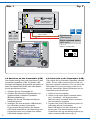
4.2 Anschluss an den Commander (LSB)
DerKopplerverfügtübereinenAnschlussfürden
ViessmannSpeedBus(LSB).DiebeidenLSB-
BuchsendesKopplerssindparallelgeschaltet,so
dassSieweitereLSB-GerätenachdemKetten-
prinzipanschließenkönnen.
1. SchaltenSiedenCommanderein.
2. SchaltenSiedieandereDigitalzentraleund
gegebenenfallsvorhandeneVerstärker
(Booster)ebenfallsein.
WartenSie,bisalleZentralenundBooster
betriebsbereitsind.
3. VerbindenSieeinederbeidenLSB-Buchsen
perLSB-KabelmitdemCommander.
AndieandereBuchsekönnenSieweitere
LSB-Geräteanschließen.DieVerbindungzum
Commanderkannauchindirektüberweitere
LSB-Geräteerfolgen(Abb.2).
4.2 Connection to the Commander (LSB)
The coupler has a Viessmann SpeedBus interface
(LSB).ThetwoLSB-connectionjacksofthecou-
plerhaveaparallelconnection.Youcaninsertthe
LSB-cableinanyjackyouwantinordertocon-
nect the Commander. More LSB-devices can be
connectedtothesecondjack.
1. SwitchontheCommander.
2. Switchontheotherdigitalcommandstation
and–ifavailable–thedigitalboosters.
Wait until every command stations and boos-
ters are ready for operation.
3. ConnectoneoftheLSB-connectionjacksvia
LSB-cablewiththeCommander.
More LSB-devices can be connected to the
secondjack.Theinterconnectiontothe
Commandercanalsobeeectedindirectlyby
otherconnectedLSB-devices(g.2).

7
Fig. 2
Abb. 2
USB2.0
HighSpeedBus
HighSpeedBus
LowSpeedBus
s88-Bus
Märklin-Booster
DCC-Booster
Programmiergleis
Programmingonthemain
Hauptgleis
Main track
Stromversorgung
Powersupply
+
-
4. DerKopplermeldetsichdannautomatischam
CommanderaufLSB-Adresse29anundkon-
guriertsichselbst(Autokonguration).
Hinweis:
NutzenSiezurVerbindungvonLSB-Gerätenbitte
unserespeziellenLSB-Kabel(Art.-Nr.5390–5393).
DiesesindmitSteckernkonfektioniertundsofort
einsetzbar.AndereKabelwiez.B.LocoNet-Kabel
oderTelefonkabelsindnichtgeeignetwegenunter-
schiedlicherSteckerbelegung!
4.3 Verbindung zweier Commander
MitHilfeeinesKopplerslassensichzweiCom-
mandermiteinanderverknüpfen.Einerderbeiden
CommanderfungiertdabeialsseparatesFahr-
undStellpult,deranderealsDigitalzentrale.
DessenHauptgleisausgangführtzumEingang
desKopplersundvondortperSpeedBuszum
Commander.DerAnschlusserfolgtwieobenbe-
schrieben.
5. Konguration
GrundsätzlichkongurierensichGeräteamViess-
mannSpeedBusautomatisch.Dieentsprechende
OptionaufdemAnmeldefensterdesCommanders
solltenSiemöglichstimmerwählen,ummöglichen
Adresskoniktenvorzubeugen.
5.1 Werkseinstellungen
AbWerkistderKoppleraufdieLSB-Adresse29
(Default-Adresse)festeingestellt.
4. Thecouplerregistersitselfautomaticallyatthe
Commanderbyautocongurationthen(LSB-
address29).
Notice:
ToconnectLSB-devices,pleaseuseourspecialLSB-
cables(item-No.5390–5393).Thesecableshave
the appropriate connectors and are ready to use.
Othercableslikee.g.LocoNet-cablesortele-
phone cables are not suitable because they have
adierentconnectorlayout!
4.3 Connection of two Commanders
Byusingacoupler,youcanconnecttwoCom-
manders. One of the Commanders takes over the
functionofthecommandstation(master)andone
of the Commanders takes over the function of a
switchboardresp.locomotioncontroller(slave).
The slave Commander sends its orders via track
format and coupler to the master Commander.
The connection is done as described above.
5. Conguration
LSB-deviceswhichareconnectedviatheViessmann
SpeedBusregisterandcongureautomaticallyatthe
Commander. Choose the appropriate option on the
Commanderscreentoavoidaddressconicts.
5.1 Factory setting
ThecouplerissettotheLSB-address29.This
address is reserved for the coupler and cannot be
changed.
Anschlüsse des Commanders / Plugs of the Commander

Modellbauartikel, kein Spielzeug! Nicht geeignet für Kinder
unter 14 Jahren! Anleitung aufbewahren!
Model building item, not a toy! Not suitable for children
under the age of 14 years! Keep these instructions!
Ce n’est pas un jouet. Ne convient pas aux enfants de
moins de 14 ans ! C’est un produit décor! Conservez cette
notice d’instructions!
Não é um brinquedo!Não aconselhável para menores de
14 anos. Conservar a embalagem.
Modelbouwartikel, geen speelgoed! Niet geschikt voor
kinderen onder 14 jaar! Gebruiksaanwijzing bewaren!
Articolo di modellismo, non è un giocattolo! Non adatto
a bambini al di sotto dei 14 anni! Conservare instruzioni
per l’uso!
Artículo para modelismo ¡No es un juguete! No
recomendado para menores de 14 años! Conserva las
instrucciones de servicio!
DE
EN
FR
NL
IT
ES
PT
Modellspielwaren GmbH
Am Bahnhof 1
D - 35116 Hatzfeld-Reddighausen
www.viessmann-modell.de
8
DieaktuelleVersionderAnleitungndenSieaufder
Viessmann-HomepageunterderArtikelnummer.
The latest version of the manual can be looked up
attheViessmannhomepageenteringtheitem-No.
5.2 Kontroll-LED
DieroteKontrollleuchtenebenderTaste„Reset“
zeigtoptischdenBetriebszustandan:
leuchtet dauerhaft=Koppleran,Regelbetrieb
blinkend=KurzschlussbeisendenderZentrale
5.3 Reset
DieTaste„Reset“istohneFunktion!
6. Fehlersuche und Abhilfe
JedesViessmann-ProduktwirdunterhohenQuali-
tätsstandardsgefertigtundvorseinerAuslieferung
geprüft.SollteesdennochzueinerStörungkom-
men,prüfenSiebittealserstesdieVerkabelung.
WennSiedieFehlerursachenichtndenkönnen,
nehmenSiebitteKontaktmitunsauf(service@
viessmann-modell.com).
SendenSiedasModellzurKontrollebzw.Repa-
raturbitteerstnachRücksprachemitunsanden
Viessmann-Service.DieAdressendenSieunten.
5.2 Control LED
The red control LED beside the “Reset” button
showsthestatusofthecoupler:
LED on=coupleron,standardoperation
LED blinking =shortcircuitatthesendingcom-
mandstation(trackformatinput)
5.3 Reset
The “Reset” button has no function!
6. Trouble-shooting
Every Viessmann product is manufactured under
highqualitystandardsandistestedbeforedeliv-
ery.Shoulddespiteofthisafaultoccur,please
checkrstthepowersupplyandthewiring.
Ifyoucannotndthefailurecausepleasecontact
ourservicedepartment(service@viessmann-
modell.com).
Ifneededsendthemodelafterconsultingthe
Viessmannservicedepartmentforcheckingand
repair.Addressseebelow.
92342
Stand02/sw
07/2016
Ho/Pic/Me
7. Technische Daten
Maße: 108mmx70mmx23mm
Anschlüsse:2xLSB,Digitaleingang(Gleissignal)
Betriebsspannung: max.30VDigitalspannung
Digitalsysteme: Märklin-Motorola/NMRA-DCC
Schutzklasse/Isolation: IP20
Temperatur(Betrieb): 0–40°C
Temperatur(Lagerung): -10–60°C
7. Technical data
Dimensions: 108mmx70mmx23mm
Connections:2xLSB,digitalinput(tracksignal)
Operatingvoltage:max.30Vdigitaltrackpower
Digitalsystems: Märklin-Motorola/NMRA-DCC
Isolation: IP20
Temperature(operation): 0–40°C
Temperature(storage): -10–60°C
EntsorgenSiediesesProduktnichtüber
den(unsortierten)Hausmüll,sondern
führenSieesderWieder-verwertungzu.
Donotdisposethisproductthrough(unsorted)
generaltrash,butsupplyittotherecycling.
-
 1
1
-
 2
2
-
 3
3
-
 4
4
-
 5
5
-
 6
6
-
 7
7
-
 8
8


in anderen Sprachen
- English: Viessmann 5302 Owner's manual
Verwandte Artikel
-
Viessmann 2624 Bedienungsanleitung
-
-
-
-
-
-
-
-
