
FR22-30
FAN CONTROLLER
Installation and
Operating Instructions
A
NL
D
I
F
GB
GB
NL
D
A
F
I
GR

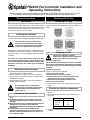
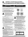
PLEASE NOTE:
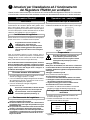
THE CANADIAN (CSA) VERSION OF THIS FAN IS RATED AT 95W THIS IS FOR
CONNECTION TO TYPE B1 AND B2 FANS ONLY.
SEE "IDENTIFYING FAN TYPE" SECTION.

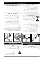
Low High
0I
45mm
210mm
86
m
m
86
m
m
208mm
Low Hi gh
0I
41mm
210mm
8
6m
m
8
1m
m
182mm
F1
F3
F4
F5
E
N
1
2
3
NF
3
2
1
L N E
L
N
11
14
13
12
F2
N
L3
2
1
L
N
13
11
12
E
N
NF
3
2
1
L
E
N
L
2
3
NF
E
N
2
1
L3
L
N
12
13
11
1
9
5
4
3
8
2
1
6
7
10
F6
14
14
L
N

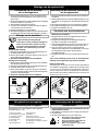
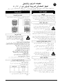
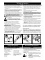
♦ A double pole isolating switch with a minimum contact
gap of 3mm (Wall or Ceiling mounted).
♦ Suitably rated 5-core cable to connect the controller to
the fan. If the fan is window mounted, use flexible cable
(Available from Xpelair).
♦ Suitably rated 3-core cable to connect the controller to
the Main Electrical Supply.
If using flexible cable, suitable glands
incorporating cable clamps must be fitted
to the knockouts in the Controller Box.
(Refer to Fig. 1).
These Instructions are for the Installation and Operation of the FR22/30 Fan Controller only. For Fan
Installation and Operating Instructions refer to literature provided with the appropriate fan.
♦♦
♦♦
♦ Not where ambient temperatures are likely to exceed
50°C.
♦♦
♦♦
♦ If installed in a kitchen the Controller must not be
mounted immediately above a cooker hood or eye
level grill.
♦♦
♦♦
♦ When intended for use in possible chemical corrosive
atmospheres, consult our Technical Service
Department (Outside the UK contact your local Xpelair
distributor).
♦♦
♦♦
♦ If installed in a shower room or bathroom the
controller and isolating switch must be situated so
that they cannot be touched by persons making use
of the bath or shower.
This appliance is designed to control the operation of Xpelair
fans of the GX9, GX12, WX9, WX12, RX9 & RX12 ranges
(wall & window mounted). The controller may be either surface
mounted, or recess mounted within it’s own patress box. You
may only wire one fan to each controller.
For the purpose of these instructions current and previous
versions of the fans are identified into Type A & Type B, as
follows:
If wiring to Type A fans
A link is fitted between terminals 2 and 3 in the fan socket,
this must be removed before connecting the Controller.
If you do not remove it, the Controller will be permanently
damaged.
If wiring to Type B fans
There is no wire link to be removed.
If the fan is already installed
1 Ensure the power supply is isolated.
2 Disconnect the mains connections from the fan’s
terminal socket or from the terminal block.
3 Remove the existing wiring and make it safe.
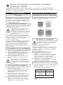
1 Route the 5-core cable from the Fan to the Controller
position.
2 Wire one end of the cable into the fan connections as
shown thus:
3 Leave the other end ready to be connected to the
Controller.
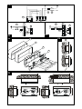
Type A1
Type A2
Type B1
Type B2
Location of the Controller
Wire the fan electrical connections
Description
What the installer will need
Identifying Fan Type
Preparing the Fan
General Information Working with the Fan
If the fan is not yet installed.
1 Check that the fan electrical rating matches the power
supply.
FAN TYPE
F1
F2
F3
DIAGRAM
Type A1
Type A2
Type B
Table 1.
If wiring to an existing installation
isolate mains supply and remove applicable
fuses prior to any electrical procedure.
FR22/30 Fan Controller Installation and
Operating Instructions
These installation instructions are for the installation of the
controller when used in combination with Xpelair supplied fans.
The controller must be installed to fixed
wiring. Ensure the Main Electrical Supply
matches the rating shown on the controller
casing.
This appliance must be earthed.
All installation must be supervised by a qualified electrician.
Installation and wiring must conform to current IEE wiring
regulations (UK), or local appropriate regulations (other
countries).
If you have any queries either before, during and after
the installation of the controller, please do not hesitate
to contact the UK Xpelair hotline (number on back page).
Customers outside the UK: contact your local Xpelair
distributor.
Installing the Controller

Remove the Cover and Mounting Frame
Eye protection must be worn during all
drilling & chiselling operations.
Check there are no buried Pipes or Cables
in the wall or obstructions on the outside
e.g. Electricity, Gas, Water.
Mounting the Wall Box
If surface mounting
1 Insert suitable glands into the knockouts.
2 Feed both cables through the glands.
3 Fix the Wall Box and Plastic Surround to the wall, using
the mounting holes provided.
4 Reconnect the earth lead to the Wall Box.
If recess mounting
1 Make a hole in the wall big enough to take the Wall Box.
Discard the Plastic Surround.
2 Insert suitable glands into the knockouts.
3 Feed both cables through these glands.
4 Fix the Wall Box to the wall. Ensure that the
flange of the mounting frame fits flush to the finished
surface of the wall (Refer diagram F6).
5 Reconnect the earth lead to the Wall Box.
Wire the Controller electrical connections
1 Mount the Isolation Switch in accordance with the
manufacturers instructions.
2 Wire the Controller to the Isolation Switch and to the Fan
as shown in the appropriate diagram (Refer to Table 1).
3 Refit Mounting Frame to Metal Wall Box.
4 Refit the Fascia to the Mounting Frame.
5 Refit the Screw Covers.
1 Ensure power supply is isolated and fuses are
removed.
2 Route the Cable from the Isolating Switch to the point of
connection to the power supply.
3 Make all connections within the Isolating Switch in
accordance with the manufacturers instructions.
4 Following all local regulations make connection at point of
power supply.
5 Make a final check to ensure all earth points are connected
and all covers have been correctly replaced on the fan,
controller and isolating switch.
6 Replace all fuses, and switch on the power supply.
For fixed wiring circuits the protective fuse for the
appliance must not exceed 5 amps.
For Australia only:
These models are permanently connected to the supply &
operation is controlled by a remote switch. They should be
directly wired to the supply through an approved 10 amp wall
mounted surface switch with at least 3mm clearance between
contacts.
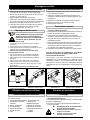
Mounting the Controller
1 Detach the Fascia from the Mounting Frame by removing
the screw covers and two screws (Refer to Fig. 2a&b).
2 Detach the Mounting Frame from the Wall Box by
removing the two screws (Refer to Fig. 2c).
3 Lift the Wall Box away from the Plastic Surround.
4 Check that the electrical rating shown inside the controller
matches the power supply.
5 Disconnect the earth wire from the Wall Box.
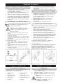
6 Make cable entry holes in the plastic and metal boxes by
removing suitable knockouts (Refer to Fig. 1).
Connect to Power Supply
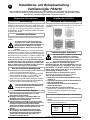
Fig. 1 : Cable Gland Positions
Fig. 2a : Removing screw covers Fig. 2b:Removing fascia Fig. 2c: Removing mounting frame
Cleaning
1 Before cleaning isolate the Controller completely
from the power supply.
2 Wipe the Cover carefully with a damp cloth.
3 Dry thoroughly.
4 Ensure ventilation slots are free from obstuctions at all
times.
♦♦
♦♦
♦
Never immerse the Controller in water
or other liquids.
♦♦
♦♦
♦
Never use solvents to clean the
Controller.
♦♦
♦♦
♦
Apart from cleaning, no other
maintenance is required.
Looking after the Controller
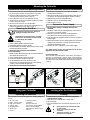
Operating the Controller
Using your Controller
1 On / Off switch
2 Intake / Extract switch
3 High / Low speed
4 Indicator light
5 Ventilation slots
6 Screw cover
7 Fascia
8 Mounting Frame
9 Wall Box
10 Plastic Surround
11 Controllers Terminal Block
12 Fan’s Terminal Block
13 Double Pole Isolator switch
14 Fuses
The Controller has the following features: (Refer to diagrams
F1-F4).

♦♦
♦♦
♦ Deze niet aanbrengen waar de omgevingstemperaturen
50CN te boven gaan.
♦♦
♦♦
♦ Wanneer in een keuken aangebracht mag de regelaar
niet direct boven een wasemkap of ooghoogte van de
grill worden gemonteerd.
♦♦
♦♦
♦ Wanneer bestemd voor gebruik in mogelijk chemisch
corrosieve atmosferen eerst onze Technische Service
afdeling raadplegen. (Buiten GB: neem contact op met
uw lokale Xpelair dealer).
♦♦
♦♦
♦ Wanneer gemonteerd in een douche- of badkamer dan
moet de regelaar daar worden aangebracht waar zij
niet kunnen worden aangeraakt door personen die de
douche of het bad gebruiken.
♦ Een tweepolige schakelaar met een minimum
contactafstand van 3 mm (muur- of plafondmontage).
♦ Passende 5-aderige kabel om de regelaar aan de ventilator
aan te sluiten. Als de ventilator raam-gemonteerd wordt
dan moet een flexibele kabel worden gebruiken.
(Verkrijgbaar bij Xpelair).
♦ Passende 3-aderige kabel voor de aansluiting van de
regelaar aan de hoofdstroomtoevoer.
Wanneer flexibele kabel wordt gebruikt
moeten passende doorvoeren worden
aangebracht via de uitbreekplaatjes in de doos
van de regelaar. (Zie Afb. 1.)
Deze voorschriften zijn uitsluitend bestemd voor de installatie en bediening van de FR22/30 ventilator-regeleenheid. Voor de
Installatie- en bedieningsvoorschriften van de ventilator gelieve u de met de betreffende ventilator meegeleverde literatuur te
raadplegen.
Dit apparaat is bedoeld om de bediening te besturen van de
Xpelair ventilatoren type GX9, GX12, WX9, WX12, RX9 &
RX12 (wand- of raammontage). De regelaar kan of op een
oppervlak worden gemonteerd, of in een uitsparing voor zijn
eigen gegalvaniseerd metalen inbouwdoos. U mag enkel één
ventilator aan elke regelaar aansluiten.
Ten behoeve van deze voorschriften worden de huidige en
vroegere versies ventilatoren geïdentificeerd als Type A &
Type B, zie hierna:
Bij aansluiting van Type A ventilatoren
In de contactdoos van de ventilator is tussen klem 2 en 3
een verbindingsdraad aangebracht die moet worden
verwijderd voordat de regelaar wordt aangesloten. Als u
de verbindingsdraad niet verwijderd zal dit permanente
beschadiging van de regelaar tot gevolg hebben.
Bij aansluiting van Type B ventilatoren
Hier hoeft geen verbindingsdraad te worden verwijderd.
Als de ventilator reeds is geinstalleerd
1. Zorg ervoor dat de netvoeding is geisoleerd.
2. Maak de elektrische aansluitingen los van de klembus
of van het klemmenblok van de ventilator.
3. Verwijder de bestaande bedrading en maak deze veilig.
Type A1
Type A2
Type B1
Type B2
Als de ventilator nog niet is geinstalleerd
1 Controleer of de toelaatbare nominale waarde van de
ventilator overeenkomt met de stroomtoevoer.
Wanneer de ventilator aan een bestaande
installatie wordt aangesloten moet eerst de
stroomtoevoer worden geisoleerd en van
toepassing zijnde zekeringen worden
verwijderd en wel voordat aan gelijk welke
elektrische procedure wordt begonnen.
Installatie- en bedieningsvoorschriften
voor de regeleenheid van de FR22/30 Ventilator
Deze installatievoorschriften zijn bestemd voor de installatie
van de besturingseenheid wanneer deze wordt gebruikt in
combinatie met door Xpelair geleverde ventilatoren.
Deze regelaar moet aan vaste bedrading
worden aangebracht. Zorg ervoor dat de
hoofdstroomtoevoer overeenkomt met
de toelaatbare nominale waarde als
afgebeeld op het huis van de regelaar.
Denk eraan, dit apparaat moet geaard
zijn.
Alle installatiewerkzaamheden moeten worden verricht onder
toezicht van een erkend elektricien.
Installatie en aansluiting moeten worden uitgevoerd conform
de huidige IEE reglementen (VK), of de lokaal van toepassing
zijnde reglementen (andere landen).
Wanneer u voor, tijdens of na de installatie van de regelaar
nog vragen mocht hebben, aarzel dan niet contact op te
nemen met de GB hotline (voor nummer zie laatste
bladzijde). Klanten buiten GB wordt aangeraden contact
op te nemen met hun plaatselijke Xpelair dealer.
Beschrijving
Algemene informatie
Installeren van de regeleenheid
Nodig voor de installatie
Aanbrengen van de regeleenheid
Preparatie van de ventilator
Werken met de ventilator
Identificeren van het type ventilator
Bedrading van de elektrische aansluitingen
van de ventilator
1. Breng de 5-aderige kabel aan van de ventilator naar de
regelaar.
2. Sluit één kant van de kabel aan in de aansluitingen van de
ventilator, als hierna afgebeeld:
3. Maak de nadere kant klaar om aan de regelaar te worden
aangesloten.
TYPE VENTILATOR
F1
F2
F3
SCHAKELSCHEMA
Type A1
Type A2
Type B
Tabel 1.
NL

Verwijdering van de afdekkap
en het montageframe
Bij alle boor- en beitelwerkzaamheden moet
oogbescherming worden gedragen.
Montage van de wanddoos
Bij oppervlakte-montage
1. Breng passende kabeldoorvoeren in de uitbreekplaatjes aan.
2. Voer beide kabels in door de doorvoeren.
3. Monteer de wanddoos en kunststof ombouw aan de muur via
de aangebrachte montagegaten.
4. Verbind de aardleiding weer aan de wanddoos.
Montage in een uitsparing
1. Maak een gat in de muur dat groot genoeg is voor de wanddoos.
Gooi de kunststof ombouw weg.
2. Breng passende kabeldoorvoeren in de uitbreekplaatjes aan.
3. Voer beide kabels in door de doorvoeren.
4. Monteer de wanddoos aan de muur. Zorg ervoor dat de flens
van het montageframe gelijk is met het afgewerkte oppervlak
van de muur. (Zie tekening F6.)
5. Verbind de aardleiding weer aan de wanddoos.
Aansluiting van de elektrische verbindingen
van de regeleenheid.
1. Monteer de scheidingsschakelaar conform de voorschriften van
de fabrikant.
2. Sluit de regeleenheid aan naar de scheidingsschakelaar en naar
de ventilator, als weergegeven in de betreffende tekening. (Zie
tabel 1.)
3. Bevestig het montageframe weer aan de metalen wanddoos.
4. Bevestig het bedieningspaneel weer aan het montageframe.
5. Breng de schroefdoppen weer aan.
1. Zorg ervoor dat de stroomtoevoer gescheiden is en de
zekeringen zijn verwijderd.
2. Breng de kabel aan van de scheidingsschakelaar naar het
aansluitpunt naar de stroomtoevoer.
3. Breng alle aansluitingen in de scheidingsschakelaar aan
conform de voorschriften van de fabrikant.
4. Volg alle lokaal geldende voorschriften op voor het maken van
een aansluiting bij het aansluitpunt voor de stroomtoevoer.
5. Voer een laatste controle uit om te verzekeren dat alle
aardpunten zijn aangesloten en alle afdekkappen weer correct
zijn aangebracht op de ventilator, regeleenheid en
scheidingsschakelaar.
6. Breng alle zekeringen weer aan en schakel de stroomtoevoer
aan.
Enkel voor Australië:
Aansluiting aan de stroomtoevoer kan worden gemaakt met
een flexibele 3-aderige kabel compleet met een 3-polige steker
voor invoer in een goedgekeurde 10 amp GPO, of kan direct
worden aangesloten via een goedgekeurde 10 amp muur-
gemonteerde oppervlakteschakelaar met (ten minste) 3 mm
afstand tussen de contacten.
Montage van de regeleenheid
Aansluiten aan de stroomtoevoer
Afb. 1: Plaatsen voor de drukringen
Afb. 2a: Verwijderen van schroefdoppen Afb. 2b: Verwijderen van bedieningspaneel Afb. 2c: Verwijderen van montageframe
Schoonmaken
1. Voorafgaand aan reiniging de stroomtoevoer naar de
regelaar geheel isoleren.
2. De afdekkap voorzichtig met een vochtige doek afnemen.
3. Goed afdrogen.
4. Houd de ventilatiegroeven vrij van obstructies.
♦♦
♦♦
♦
De regelaar nooit in water of andere
vloeistoffen onderdompelen.
♦♦
♦♦
♦
Nooit oplosmiddelen gebruiken om
regelaar schoon te maken.
♦♦
♦♦
♦
Naast schoonmaken is geen verder
onderhoud nodig.
Verzorging van de regelaar
De bediening van de regelaar
Het gebruik van uw regelaar
1. Aan/Uit schakelaar 8. Montageframe
2. Aanzuig/Afzuig schakelaar 9. Wanddoos
3. Hoog/Laag toerental 10.Kunststof ombouw
4. Verklikkerlampje 11.Klemmenblok regeleenheden
5. Ventilatiegroeven 12.Klemmenblok ventilator
6. Schroefdop 13.Dubbelpolig scheidingsschakelaar
7. Bedieningspaneel 14.Zekeringen
De regelaar kan voor het volgende worden gebruikt:
(Zie tekeningen F1 - F4.)
1. Maak het bedieningspaneel los van het montageframe door
verwijdering van de schroefdoppen en twee schroeven. (Zie
Afb. 2a & 2b.)
2. Maak het montageframe los van de wanddoos door verwijdering
van de twee schroeven. (Zie Afb. 2c.)
3. Til de wanddoos uit de kunststof ombouw.
4. Controleer of de toelaatbare nominale waarde in de regelaar
overeenkomt met de stroomtoevoer.
5. Maak de aardleiding los van de wanddoos.
6. Maak kabel-ingangsgaten in de kunststof en metalen dozen door
verwijdering van de toepasselijke uitbreekplaatjes. (Zie Afb. 1.)
Controleer of er geen verborgen leidingen of
kabels in de muur zitten, danwel of er zich
obstructies aan de buitenkant van de muur
bevinden, zoals elektriciteit, gas of water.
Voor vaste bedradingscircuits mag de beschermende
zekering voor het apparaat 5 amp niet overschrijden.

♦ Ein zweipoliger Netztrennschalter mit einer Kontaktöffnung
von 3 mm (an Wand oder Decke montiert).
♦ Ausreichend dimensionierte fünfadrige Anschlußleitung
zum Anschließen des Reglers an den Ventilator. Bei
Fenstereinbau des Ventilators sollte eine flexible
Anschlußleitung verwendet werden (bei Xpelair erhältlich).
♦ Ausreichend dimensionierte dreiadrige Anschlußleitung
zwischen Ventilator und Netzstromversorgung.
Falls eine flexible Anschlußleitung verwendet
wird, muß für ausreichende Zugentlastung
gesorgt werden (siehe Abb. 1).
Die vorliegende Anleitung bezieht sich nur auf die Installation und den Betrieb des Ventilatorreglers
FR22/30. Die Installations- und Betriebsanleitung für den Ventilator entnehmen Sie bitte dem mit dem
betreffenden Ventilator mitgelieferten Informationsmaterial.
♦♦
♦♦
♦ Der Regler darf nicht an Stellen installiert werden, an
denen eine Umgebungstemperatur von +50°C
überschritten werden könnte.
♦♦
♦♦
♦ Der Regler darf nicht in unmittelbarer Nähe von
Herdplatten, Dunstabzugshauben oder anderen
Wandöffnungen montiert werden.
♦♦
♦♦
♦ Falls der Ventilator zur Förderung möglicherweise
chemisch korrodierender Atmosphäre vorgesehen ist,
sollten Sie mit Ihrem örtlichen Xpelair-Händler
Verbindung aufnehmen (Großbritannien: bitte wenden
Sie sich an den Technischen Kundendienst von
Xpelair).
♦♦
♦♦
♦ Beim Einbau in einem Badezimmer/Duschraum
müssen Regler und Netztrennschalter gemäß den
einschlägigen Bestimmungen und so positioniert
werden, daß sie vom Bad/von der Dusche aus
nicht berührt werden können.
Dieses Gerät ist zum Regeln des Betriebs von Xpelair-
Ventilatoren der Baureihen GX9, GX12, WX9, WX12, RX9
und RX12 (wand- und fenstermontiert) bestimmt. Der Regler
ist für Auf- und Unterputzinstallation geeignet (nur
Großbritannien). Es darf nur maximal ein Ventilator pro Regler
angeschlossen werden.
Zum Zweck dieser Anleitung werden derzeitige und ältere
Ventilatorversionen wie folgt entweder Typ A oder Typ B
zugeordnet:
Beim Anschließen an Ventilatoren des Typs A
Die Brücke zwischen den Anschlußklemmen 2 und 3 in
der Anschlußbuchse des Ventilators muß vor dem
Anschließen des Reglers entfernt werden. Wird die
Brücke nicht entfernt, kann das zu einer dauerhaften
Beschädigung des Reglers führen.
Beim Anschließen an Ventilatoren des Typs B
Das Entfernen der Brücke ist hier nicht erforderlich.
Falls der Ventilator bereits installiert ist
1 Stellen Sie sicher, daß eine allpolige Netztrennung
gegeben ist.
2 Trennen Sie den Netzanschluß von der Steckbuchse
bzw. vom Klemmenbrett.
3 Überprüfen Sie die vorhandene Verdrahtung auf
elektrische Sicherheit.
1 Verlegen Sie das fünfadrige Kabel zwischen Ventilator und
Regler.
2 Schließen Sie ein Ende des Kabels wie abgebildet an die
Anschlüssen des Ventilators an:
3 Das andere Ende dient zum Anschluß an den Regler.
Typ A1
Typ A2
Typ B1
Typ B2
Installationsort des Reglers
Verdrahten der elektrischen Anschlüsse des Ventilators
Beschreibung
Was zur Installation benötigt wird
Bestimmen des Ventilatortyps
Vorbereitung des Ventilators
Allgemeine Informationen Arbeiten am Ventilator
Falls der Ventilator noch nicht installiert ist:
1 Überprüfen Sie, ob die elektrischen Anschlußdaten des
Ventilators mit denen der Netzstromversorgung
übereinstimmen.
VENTILATORTYP
F1
F2
F3
ANSCHLUSSDIAGRAMM
Typ A1
Typ A2
Typ B
Tabelle 1
Falls der Ventilator an eine existierende Anlage
angeschlossen werden soll, ist für eine
allpolige Netztrennung zu sorgen und die
betreffenden Sicherungen sind zu entfernen,
bevor mit Elektroarbeiten begonnen wird.
Installations- und Betriebsanleitung -
Ventilatorregler FR22/30
Diese Installationsanleitung behandelt die Installation des
Reglers bei Verwendung in Verbindung mit Ventilatoren von
Xpelair.
Der Regler muß an eine Festverdrahtung
angeschlossen werden. Stellen Sie sicher,
daß die auf dem Reglergehäuse angegebenen
Nennwerte mit der Netzstromversorgung
übereinstimmen. Dieses Gerät muß geerdet
werden.
Alle Installationsarbeiten dürfen nur von einer qualifizierten
Elektrofachkraft ausgeführt werden. In Großbritannien sind
Installation und Verdrahtung gemäß den derzeitig gültigen
IEE-Bestimmungen auszuführen. In anderen Ländern sind
die jeweils geltenden nationalen Vorschriften einzuhalten.
Installation des Reglers
Sollten Sie vor, bei oder nach der Installation des Reglers
irgendwelche Fragen haben, wenden Sie sich bitte an die
britische Xpelair-Hotline (Telefonnummer siehe Rückseite).
Nicht in Großbritannien befindliche Kunden von Xpelair
wenden sich an ihren örtlichen Xpelair-Händler.
D

Entfernen der Abdeckung und des Montagerahmens
Während der gesamten Dauer der Bohr- und
Meißelvorgänge muß ein Augenschutz getragen
werden.
Montage des Wandkastens
Bei Aufputzmontage
1 Setzen Sie geeignete Kabelverschraubungen in die
Ausbrüche ein.
2 Führen Sie beide Kabel durch diese Verschraubungen.
3 Befestigen Sie den Wandkasten und die Kunststoffeinfassung
über die vorgesehenen Montagelöcher an der Wand.
4
Schließen Sie den Erdungsleiter wieder am Wandkasten an.
Bei Unterputzeinbau
1 Fertigen Sie eine Vertiefung in der Wand zur Aufnahme des
Wandkastens an. Die Kunststoffeinfassung wird für die
Unterputzmontage nicht benötigt.
2 Setzen Sie geeignete Kabelverschraubungen in die Ausbrüche
ein.
3 Führen Sie beide Kabel durch diese Verschraubungen.
4 Befestigen Sie den Wandkasten an der Wand. Achten Sie
darauf, daß der Flansch des Montagerahmens an der fertigen
Wandoberfläche bündig anliegt (siehe Diagramm F6).
5 Schließen Sie den Erdungsleiter wieder am Wandkasten an.
Elektrischer Anschluß des Reglers
1 Montieren Sie den Netztrennschalter gemäß der Anleitung des
Herstellers.
2 Schließen Sie den Regler in Übereinstimmung mit dem
entsprechenden Diagramm an den Netztrennschalter und den
Ventilator an (siehe Tabelle 1).
3 Bringen Sie den Montagerahmen wieder am Wandkasten
(Metall) an.
4 Bringen Sie die Frontplatte wieder am Montagerahmen an.
5 Bringen Sie die Schraubenabdeckungen wieder an.
1 Stellen Sie sicher, daß eine allpolige Netztrennung
gegeben ist und die Sicherungen entfernt werden.
2 Verlegen Sie das Kabel vom Netztrennschalter zum
Netzstromversorgungsanschlußpunkt.
3 Stellen Sie in Übereinstimmung mit der Anleitung des
Herstellers alle Anschlüsse im Netztrennschalter her.
4 Stellen Sie unter Einhaltung aller einschlägigen Vorschriften
den Netzstromanschluß her.
5 Überprüfen Sie abschließend, daß alle Erdungspunkte
angeschlossen sind und alle Abdeckungen an Ventilator,
Regler und Netztrennschalter wieder richtig angebracht worden
sind.
6 Setzen Sie alle Sicherungen wieder ein und schalten Sie die
Netzstromversorgung ein.
(Großbritannien:) Bei Festverdrahtung darf die
Schutzsicherung für das Gerät den Nennstrom von 5 A nicht
überschreiten.
Nur Australien:
Diese Modelle sind permanent an die Stromversorgung
angeschlossen und ihr Betrieb wird über einen separaten Schalter
gesteuert. Sie sollten durch einen zugelassenen aufputzmontierten
10-A-Schalter mit einem Mindestabstand von 3 mm zwischen
Kontakten direktverdrahtet sein.
Montage des Reglers
1 Lösen Sie die Frontplatte vom Montagerahmen, indem Sie die
Schraubenabdeckungen abnehmen und die zwei Schrauben
entfernen (siehe Abb. 2a und 2b).
2 Lösen Sie den Montagerahmen vom Wandkasten durch
Herausschrauben der zwei Schrauben (siehe Abb. 2c).
3 Ziehen Sie den Wandkasten von der Kunststoffeinfassung ab.
4 Überprüfen Sie, ob die elektrische Auslegung auf der Innenseite
des Reglers mit der Stromversorgung übereinstimmt.
5 Klemmen Sie den Erdungsanschluß vom Wandkasten ab.
6 Öffnen Sie die Kabeleingangslöcher in den Kunststoff- und
Metallkästen durch Ausbrechen der vorgesehenen
Sollbruchstellen (siehe Abb. 1).
Anschluß an die Stromversorgung
Reinigung
1 Der Regler ist vor der Reinigung allpolig vom Netz zu trennen.
2 Die Abdeckung sorgfältig mit einem feuchten Tuch abwischen.
3 Gründlich abtrocknen.
4 Stellen Sie sicher, daß die Lüftungsschlitze nie verdeckt oder
verstopft werden.
♦ ♦
♦ ♦
♦
Der Regler darf auf keinen Fall in Wasser oder andere
Flüssigkeiten eingetaucht werden.
♦ ♦
♦ ♦
♦
Den Regler niemals mit Lösungsmitteln reinigen.
♦ ♦
♦ ♦
♦
Abgesehen von der Reinigung ist keine weitere
Wartung erforderlich.
Instandhaltung des Reglers
Betrieb des Reglers
Benutzung des Reglers
1 Ein/Aus-Schalter
2 Zuluft/Abluft-Schalter
3 Hohe/Niedrige Geschwindigkeit
4 Betriebsleuchte
5 Lüftungsschlitze
6 Schraubenabdeckung
7 Frontplatte
8 Montagerahmen
9 Wandkasten
10 Kunststoffeinfassung
11 Klemmenbrett des Reglers
12 Klemmenbrett des Ventilators
13 Zweipoliger Netztrennschalter
14 Sicherungen
Der Regler besitzt folgende Funktionen
(siehe Diagramme F1 - F4):
Vergewissern Sie sich, daß sich an der
gewünschten Montageposition keine
eingelassenen Leitungen, wie z.B. Strom-, Gas-
oder Wasserleitungen, befinden, welche bei der
Installation eventuell beschädigt werden
könnten.
Abb.1 Abb.2a : Abb.2b: Abb.2c:
Positionen der Kabelverschraubungen Abnehmen der Schraubenabdeckungen Abnehmen der Frontplatte Abnehmen des Montagerahmens


A

♦ Un interrupteur bipolaire de coupure avec intervalle de
coupure minimal de 3 mm (Montage mural ou au plafond).
♦ Un câble à 5 conducteurs de caractéristiques adéquates
pour relier le contrôleur au ventilateur. Si le ventilateur
est monté sur une fenêtre, utilisez un câble souple.
(Disponible chez Xpelair).
♦ Un câble à 3 conducteurs de caractéristiques adéquates
pour relier le contrôleur à l’alimentation secteur.
Si vous utilisez un câble flexible, des presse-
étoupe adéquats équipés de colliers de
serrage doivent être montés sur les pastilles
préformées de la boîte du contrôleur. (Voir
Fig. 1).
Ces instructions concernent uniquement l’installation et l’utilisation du contrôleur de ventilateur FR22/30. Pour les instructions
sur l’installation et l’utilisation du ventilateur, référez-vous aux documents
♦ Pas où les températures ambiantes peuvent
dépasser 50°C.
♦ S’il est installé dans une cuisine, le contrôleur ne
doit pas être monté directement au dessus d’une
hotte de cuisinière ou d’un grill à hauteur d’oeil.
♦ S’il est destiné à être utilisé dans des atmosphères
chimiques pouvant être corrosives, demandez
conseil à notre Service Technique. (En dehors du
Royaume-Uni, contactez votre distributeur Xpelair
local).
♦ S’il est installé dans une salle de douche ou une
salle de bain, le contrôleur et lecommutateur
d’isolation doivent être placés de manière qu’ils ne
puissent être touchés par les personnes utilisant le
bain ou la douche.
Cet appareil est conçu pour contrôler le fonctionnement des
ventilateurs Xpelair des gammes GX9, GX12, WX9, WX12,
RX9 et RX12 (montage mural et sur fenêtres). Le contrôleur
peut être soit monté en saillie, soit encastré dans sa propre
boîte
.
Vous ne devez pas relier plus d’un ventilateur à chaque
contrôleur
Pour les besoins de ces instructions, les versions actuelles
et précédentes des ventilateurs sont identifiées en Type A &
Type B, comme suit :
Dans le cas de câblage à des ventilateurs de Type A
Il y a un cavalier entre les bornes 2 et 3 dans la prise du
ventilateur, et ce cavalier doit être retiré avant de relier le
contrôleur. Si vous ne le retirez pas, le contrôleur sera
définitivement endommagé.
Dans le cas de câblage à des ventilateurs de Type B
Il n’y a pas de cavalier à retirer.
Si le ventilateur est déjà installé
1 Assurez-vous que l’alimentation secteur est coupée.
2 Débranchez les connexions du secteur de la prise à
bornes du ventilateur ou du bornier.
3 Retirez les fils existants et mettez en sécurité.
1 Faites passer le câble à 5 conducteurs du ventilateur au
contrôleur
2 Reliez une extrémité du câble aux connexions du
ventilateur comme indiqué ci-après :
3 Laissez l’autre extrémité prête à être reliée au contrôleur
Type A1
Type A2
Type B1
Type B2
Emplacement du contrôleur
Câblage des connexions électriques du ventilateur
Description
Ce dont l’installateur a besoin
Identification du type de ventilateur
Préparation du ventilateur
Informations Générales
Si le ventilateur n’est pas encore installé
1 Vérifiez que les caractéristiques électriques du ventilateur
correspondent à l’alimentation électrique.
Dans le cas de câblage à une installation
existante, isolez l’alimentation secteur et
retirez les fusibles concernés avant toute
procédure électrique
Instructions d’installation et d’utilisation du
Contrôleur de ventilateur FR22/30
Ces instructions d’installation concernent l’installation du
contrôleur lorsqu’il est utilisé avec des ventilateurs fournis
par Xpelair.
Le contrôleur doit être relié à un câblage
fixe. Assurez-vous que l’alimentation secteur
correspond aux caractéristiques indiquées
sur le boîtier du contrôleur. Cet appareil
doit être mis à la terre.
Toutes les installations doivent être supervisées par un
électricien qualifié. L’installat(ion et le câblage doivent être
conformes aux règlements actuels IEE (R-U), ou aux
règlements locaux appropriés (autres pays).
Si vous avez des questions avant, pendant et après
l’installation du contrôleur, n’hésitez pas à contacter le
numéro britannique d’urgence de Xpelair (numéro sur la
dernière page). Pour les clients hors du Royaume-Uni,
contactez votre distributeur Xpelair local.
Utilisation du ventilateur
TYPE
F1
F2
F3
SCHEMA
Type A1
Type A2
Type B
Tableau 1.
Installation du contrôleur
F
Type B, comme suit:

Retrait du couvercle et du cadre de montage
Des lunettes de protection doivent être
portées pendant tout perçage ou burinage.
Vérifiez qu’il n’y a aucune tuyauterie ou
câble enfoui dans le mur ou d’obstructions
à l’extérieur, par ex. électricité, gaz, eau.
Montage du boîtier mural
Pour le montage en saillie
1 Insérer des manchons appropriés dans les pastilles
préformées
2 Faites passer les deux câbles dans les manchons
3 Fixez le boîtier mural et la bordure en plastique au mur, à
l’aide des trous d’assemblage prévus
4 Reliez à nouveau le fil de terre au boîtier mural
Pour le montage encastré
1 Faites un trou dans le mur suffisamment grand pour
loger le boîtier mural. Jetez la bordure en plastique
2 Insérez des manchons appropriés dans les pastilles
préformées
3 Faites passer les deux câbles dans ces manchons
4 Fixez le boîtier au mur. Assurez-vous que la bride du
cadre de montage affleure la surface finie du mur. (Voir
le schéma F6).
5 Rebrancher le fil de terre sur le boîtier encastré.
Câblage des connexions électriques du contrôleur
1 Montez le commutateur d’isolation conformément aux
instructions des fabricants.
2 Câblez le contrôleur au commutateur d’isolation et au
ventilateur comme illustré sur le schéma approprié. (Voir
le Tableau 1).
3 Remontez le cadre de montage dans le boîtier mural
4 Remontez l la face sur le cadre de montage
5 Remontez les couvre-vis
1 Assurez-vous que l’alimentation secteur est coupée
et que les fusibles sont retirés
2 Faites passer le câble entre le commutateur d’isolation et
le point de connexion à l’alimentation secteur
3 Faites toutes les connexions dans le commutateur
d’isolation conformément aux instructions des fabricants.
4 En respectant tous les règlements locaux, branchez à
l’alimentation secteur.
5 Faites une dernière vérification pour assurer que tous les
points de mise à la terre sont connectés et que tous les
couvercles ont été correctement remis sur le ventilateur,
le contrôleur et le commutateur d’isolation.
6 Remettez tous les fusibles, et mettez sous tension secteur.
Pour des circuits avec raccordement fixe, le fusible de
protection de l’appareil ne doit pas dépasser 5 A.
Pour l’Australie uniquement :
Ces modèles sont reliés de manière permanente à
l’alimentation et le fonctionnement est commandé par un
interrupteur à distance. Ces modèles doivent être câblés
directement au secteur à l’aide d’un commutateur mural de
10 A approuvé, avec un écartement des contacts d’au moins
3 mm
Montage du contrôleur
1 Enlever l’avant du cadre de montage en retirant les
couvercles de vis et les deux vis. (Voir la Fig. 2a&b).
2 Enlever le cadre de montage du boîtier mural en retirant
les deux vis. (Voir la Fig. 2c).
3. Retirez le boîtier de la bordure en plastique.
4 Vérifiez que la puissance électrique indiquée à l’intérieur
du contrôleur correspond à celle de l’alimentation principale.
5 Débranchez du boîtier mural le fil de mise à la terre.
6 Faites des trous d’entrée pour le câble dans les boîtiers
en plastique et métalliques en retirant les pastilles
préformées appropriées. (Voir la Fig. 1).
Connectez au secteur
Fig. 1 :
Positions des presse-étoupe
1 Avant de nettoyer, isolez complètement le contrôleur
de l’alimentation électrique
2 Essuyez le couvercle soigneusement avec un chiffon humide
3 Séchez complètement
4 Assurez-vous toujours que les fentes de ventilation ne
sont pas bouchées.
♦♦
♦♦
♦
N’immergez jamais le contrôleur dans
de l’eau ou un autre liquide
♦♦
♦♦
♦
N’utilisez jamais de solvants forts pour
nettoyer le contrôleur
♦♦
♦♦
♦
A part le nettoyage, aucun autre
entretien n’est nécessaire.
Entretien du contrôleur
Utilisation de votre contrôleur
1 Commutateur Marche/Arrêt
2 Commutateur aspiration/
extraction
3 Vitesse rapide/lente
4 Voyant lumineux
5 Fentes de ventilation
6 Couvercle de vis
7 Face
Le contrôleur comporte les caractéristiques suivantes : (Voir
les schémas F1-F4).
Fig. 2a :
Retrait des couvercles de vis
Fig. 2c :
Retrait du cadre de montage
Fig. 2b :
Retrait de la face
8 Cadre de montage
9 Boîtier mural
10Bordure plastique
11Bornier du contrôleur
12Bornier du ventilateur
13Interrupteur bipolaire de
coupure
14Fusibles
Fonctionnement du contrôleur Nettoyage

♦ Un isolatore bipolare con una distanza minima tra i contatti
di 3 mm (montaggio a parete o a soffitto).
♦ Cavo a 5 conduttori per collegare il regolatore al ventilatore.
Se il ventilatore è montato su una finestra usare un cavo
flessibile (disponibile presso Xpelair).
♦ Cavo a 3 conduttori per collegare il regolatore
all'alimentazione di rete.
Se si usa un cavo flessibile, si devono montare
opportuni pressatreccia, che incorporano
morsetti serrafilo, ai fori incompleti nella
cassetta del regolatore (vedere fig. 1).
Queste istruzioni sono soltanto per l'installazione ed il funzionamento del Regolatore FR22/30. Per le istruzioni
di installazione e funzionamento del ventilatore consultare la documentazione fornita con il relativo ventilatore.
♦♦
♦♦
♦ Non posizionare il regolatore dove la temperatura
ambiente potrebbe superare 50ºC.
♦♦
♦♦
♦ Se viene installato in una cucina, non si deve montare
il regolatore sopra una cappa di aspirazione o un grill
all'altezza del viso.
♦♦
♦♦
♦ Se si prevede l'uso in atmosfere corrosive da sostanze
chimiche, consultare il distributore locale Xpelair.
♦♦
♦♦
♦ Se vengono installati in una stanza da bagno o doccia,
il regolatore e l'isolatore devono essere posizionati in
modo che non possano essere toccati da chi usa il
bagno o la doccia.
Questo dispositivo è stato progettato per regolare il
funzionamento dei ventilatori Xpelair della gamma GX9,
GX12, WX9, WX12, RX9 e RX12 (montati a parete e su
finestra). Il regolatore può essere montato in superficie oppure
a incasso nella propria cassetta di metallo zincato. Si deve
cablare un solo ventilatore a ciascun regolatore.
Ai fini di queste istruzioni, le versioni correnti e precedenti dei
ventilatori sono identificate come Tipo A e Tipo B, come segue:
Cablaggio a ventilatori Tipo A
Nella presa del ventilatore, tra i morsetti 2 e 3 è montato
un filo fusibile che deve essere tolto prima di collegare il
regolatore, altrimenti il regolatore sarà permanentemente
danneggiato.
Cablaggio a ventilatori Tipo B
Non è presente filo fusibile da togliere.
Se il ventilatore è già installato:
1 Assicurarsi che l'alimentazione elettrica sia isolata.
2 Scollegare le connessioni di rete dalla presa terminale
del ventilatore o dal blocco terminale.
3 Togliere il cablaggio esistente e renderlo sicuro.
1 Instradare il cavo a 5 conduttori dal ventilatore alla
posizione del regolatore.
2 Cablare un'estremità del cavo nelle connessioni del
ventilatore come indicato di seguito:
3 Lasciare l'altra estremità pronta per essere collegata al
regolatore.
Tipo A1
Tipo A2
Tipo B1
Tipo B2
Posizionamento del regolatore
Cablaggio delle connessioni elettriche del
ventilatore
Descrizione
Che cosa occorre all'installatore
Identificazione del tipo di ventilatore
Preparazione
Informazioni Generali Operazioni con i ventilatori
Se il ventilatore non è ancora installato:
1 Controllare che l'alimentazione elettrica nominale del
ventilatore corrisponda all'alimentazione di rete.
TIPO DI VENTILATORE
F1
F2
F3
DIAGRAMMA
Tipo A1
Tipo A2
Tipo B
Tabella 1.
Se si deve effettuare il collegamento ad
un'installazione già esistente, isolare
l'alimentazione di rete e togliere i relativi
fusibili prima di qualunque procedura
elettrica.
Istruzioni per l'installazione ed il funzionamento
del Regolatore FR22/30 per ventilatori
Queste istruzioni sono intese per l'installazione del regolatore
quando viene usato con ventilatori forniti da Xpelair.
Il regolatore deve essere installato con
cablaggio fisso. Controllare che
l'alimentazione di rete corrisponda ai dati
riportati sull'alloggiamento del regolatore.
Questo dispositivo deve essere collegato a
massa.
Tutte le installazioni devono essere eseguite sotto la
supervisione di un elettricista qualificato. L'installazione e i
cablaggi devono essere conformi alle norme IEE (Regno
Unito) o alle relative norme locali (per altri Paesi).
Se si desiderano ulteriori informazioni prima, durante e
dopo l'installazione del regolatore, rivolgersi al numero
di assistenza Xpelair nel Regno Unito (riportato all'ultima
pagina). Clienti fuori del Regno Unito: rivolgersi al
distributore locale Xpelair.
Installazione del regolatore
I

Togliere il coperchio e il telaio di montaggio
Durante le operazioni di trapanatura e
scalpellatura si devono indossare protezioni
per gli occhi.
Montaggio della cassetta a parete
Montaggio in superficie
1 Inserire pressatreccia adatti nei fori incompleti.
2 Far passare entrambi i cavi nei pressatreccia.
3 Fissare al muro la cassetta e la cornice di plastica
utilizzando i fori di montaggio forniti.
4 Ricollegare il filo di massa alla cassetta a parete.
Montaggio a incasso
1 Praticare nella parete un foro abbastanza grande per
alloggiare la cassetta. Gettare la cornice di plastica.
2 Inserire pressatreccia adatti nei fori incompleti.
3 Far passare entrambi i cavi nei pressatreccia.
4 Fissare la cassetta alla parete. Assicurarsi che la flangia
del telaio di montaggio sia a filo con la superficie della
parete (vedere il diagramma F6).
5 Ricollegare il filo di massa alla cassetta a parete.
Cablaggio delle connessioni elettriche del regolatore
1 Montare l'isolatore seguendo le istruzioni del fabbricante.
2 Cablare il regolatore all'isolatore ed al ventilatore, come
indicato nel relativo diagramma (vedere la Tabella 1).
3 Rimontare il telaio di montaggio alla cassetta metallica a
parete.
4 Rimontare il pannello al telaio di montaggio.
5 Rimettere i coperchi alle viti.
1 Assicurarsi che l'alimentazione elettrica sia isolata e
che i fusibili siano stati tolti.
2 Far passare il cavo dall'isolatore al punto di connessione
con l'alimentazione elettrica.
3 Eseguire tutte le connessioni nell'isolatore conformemente
alle istruzioni del fabbricante.
4 Eseguire le connessioni al punto dell'alimentazione elettrica
seguendo tutte le norme vigenti localmente.
5 Eseguire una verifica finale per assicurarsi che tutti i punti
di massa siano collegati e che tutte le coperture siano state
rimesse a posto nel modo giusto sul ventilatore, regolatore
ed isolatore.
6 Rimettere tutti i fusibili ed inserire l'alimentazione elettrica.
Per i circuiti a cablaggio fisso, il fusibile di protezione
dell'apparecchio non deve essere superiore a 5 amp.
Solo per l'Australia:
Questi modelli sono collegati in permanenza all'alimentazione
e il funzionamento è controllato da un interruttore remoto. I
modelli devono essere cablati direttamente all'alimentazione
tramite un interruttore di 10 amp approvato, montato in
superficie sulla parete con almeno 3 mm di spazio tra i contatti.
Montaggio del regolatore
1 Smontare la parte anteriore dal telaio di montaggio togliendo
le coperture delle viti e due viti (vedere figg. 2a e 2b).
2 Staccare il telaio dalla cassetta a parete togliendo le due viti
(vedere fig. 2c).
3 Allontanare la cassetta sollevandola dalla cornice di plastica.
4 Controllare che i dati elettrici nominali riportati all'interno del
regolatore corrispondano all'alimentazione elettrica.
5 Scollegare il filo di massa dalla cassetta a parete.
6 Praticare fori di ingresso dei cavi nella cassetta di plastica e
in quella di metallo aprendo i fori incompleti (vedere fig. 1).
Collegamento dell'alimentazione elettrica
Fig. 1 : Fig. 2a : Fig. 2b: Fig. 2c:
Pulizia
1 Prima di procedere alla pulizia isolare completamente
il regolatore dall'alimentazione elettrica.
2 Pulire delicatamente il coperchio con un panno umido.
3 Asciugare bene.
4 Assicurarsi che le fessure di ventilazione non siano mai
ostruite.
♦♦
♦♦
♦
Non immergere mai il regolatore in acqua
o altri liquidi.
♦♦
♦♦
♦
Non usare mai solventi per pulire il
regolatore.
♦♦
♦♦
♦
Tranne la pulizia, non è necessaria altra
manutenzione.
Manutenzione del regolatore
Funzionamento del regolatore
Impiego del regolatore
1 Interruttore On/Off 8 Telaio di montaggio
2 Interruttore aspirazione/ 9 Cassetta a parete
estrazione 10 Cornice di plastica
3 Velocità alta/bassa 11 Blocco morsetti regolatore
4 Spia luminosa 12 Blocco morsetti ventilatore
5 Fessure di ventilazione 13 Isolatore bipolare
6 Copri vite 14 Fusibili
7 Pannello
Il regolatore ha le seguenti caratteristiche.
(vedere i diagrammi F1-F4).
Check there are no buried Pipes or Cables
in the wall or obstructions on the outside
e.g. Electricity, Gas, Water.
Posizioni dei pressatreccia del cavo Rimozione dei coperchi delle viti Rimozione del pannello Rimozione del telaio di montaggio
Controllare che non vi siano tubi o cavi
nascosti nel muro o ostruzioni all’esterno, per
es. condotte per elettricità, gas, acqua.

∏ Û˘Û΢‹ ÚÔÔÚ›˙ÂÙ·È ÁÈ· ÙË Ú‡ıÌÈÛË Ù˘ ÏÂÈÙÔ˘ÚÁ›·˜ ÙˆÓ
ÂÍ·ÂÚÈÛÙ‹ÚˆÓ Xpelair ÙˆÓ ÛÂÈÚÒÓ GÃ9, GX12, WX9, WX12,
RX9 Î·È RX12 (Ô˘ ÙÔÔıÂÙÔ‡ÓÙ·È Û ÙÔ›¯Ô˘˜ Î·È ·Ú¿ı˘Ú·).
√ Ú˘ıÌÈÛÙ‹˜ ÌÔÚ› Ó· ÙÔÔıÂÙÂ›Ù·È Û ÂÈÊ¿ÓÂÈ· ‹ Û ÂÛÔ¯‹
̤۷ ÛÙÔ ‰ÈÎfi ÙÔ˘ ÎÈ‚ÒÙÈÔ. ªÔÚ›Ù ӷ ηψ‰ÈÒÛÂÙ ÌfiÓÔ
¤Ó· ÂÍ·ÂÚÈÛÙ‹Ú· Û οı ڢıÌÈÛÙ‹.
√È Ô‰ËÁ›Â˜ ·˘Ù¤˜ ÈÛ¯‡Ô˘Ó ÁÈ· ÙËÓ ÂÁηٿÛÙ·ÛË ÙÔ˘ Ú˘ıÌÈÛÙ‹
fiÙ·Ó ¯ÚËÛÈÌÔÔÈÂ›Ù·È ÛÂ Û˘Ó‰˘·ÛÌfi Ì ÂÍ·ÂÚÈÛÙ‹Ú˜ Ô˘
ÚÔÌËı‡ÔÓÙ·È ·fi ÙËÓ Xpelair.
∏ ÂÁηٿÛÙ·ÛË ÙÔ˘ Ú˘ıÌÈÛÙ‹ Ú¤ÂÈ Ó· Á›ÓÂÙ·È
Û ÛÙ·ıÂÚ‹ ηψ‰›ˆÛË. µÂ‚·Èˆı›Ù fiÙÈ Ë
‰È·‚¿ıÌÈÛË Ù˘ ÎÂÓÙÚÈ΋˜ ËÏÂÎÙÚÈ΋˜ ·ÚÔ¯‹˜
Â›Ó·È Û‡ÌʈÓË Ì ÙË ‰È·‚¿ıÌÈÛË Ô˘ ·Ó·Ê¤ÚÂÙ·È
ÛÙÔ ÂÚ›‚ÏËÌ· ÙÔ˘ Ú˘ıÌÈÛÙ‹. ∏ Û˘Û΢‹ ·˘Ù‹
Ú¤ÂÈ Ó· ÁÂÈÒÓÂÙ·È.
∏ fiÏË ÂÁηٿÛÙ·ÛË Ú¤ÂÈ Ó· ÂȂϤÂÙ·È ·fi ÂȉÈÎÂ˘Ì¤ÓÔ
ËÏÂÎÙÚÔÏfiÁÔ. ∏ ÂÁηٿÛÙ·ÛË Î·È Ë Î·Ïˆ‰›ˆÛË Ú¤ÂÈ Ó·
Û˘ÌÌÔÚÊÒÓÔÓÙ·È ÚÔ˜ ÙÔ˘˜ ÙÚ¤¯ÔÓÙ˜ ηÓÔÓÈÛÌÔ‡˜ ÙÔ˘ π∂∂
(ÛÙÔ ∏ӈ̤ÓÔ µ·Û›ÏÂÈÔ) ‹ ÙÔ˘˜ Û¯ÂÙÈÎÔ‡˜ ÂıÓÈÎÔ‡˜
ηÓÔÓÈÛÌÔ‡˜ (Û ¿ÏϘ ¯ÒÚ˜).
∞Ó ¤¯ÂÙ ÔÔÈÂÛ‰‹ÔÙ ÂÚˆÙ‹ÛÂȘ ÚÈÓ, ηٿ Î·È ÌÂÙ¿ ÙËÓ
ÂÁηٿÛÙ·ÛË ÙÔ˘ Ú˘ıÌÈÛÙ‹, ·Ú·Î·Ï›Ûı ӷ ÌË ‰ÈÛÙ¿ÛÂÙÂ
Ó· ÂÈÎÔÈÓˆÓ‹ÛÂÙ Ì ÙËÓ ÙËÏÂʈÓÈ΋ ÁÚ·ÌÌ‹ ¿ÌÂÛ˘
Û‡Ó‰ÂÛ˘ (hotline) Ù˘ Xpelair ÛÙÔ ∏ӈ̤ÓÔ µ·Û›ÏÂÈÔ
(‚Ϥ ·ÚÈıÌfi ÛÙËÓ ›Ûˆ ÛÂÏ›‰·). √È ÂÎÙfi˜ ∏ӈ̤ÓÔ˘
µ·ÛÈÏ›Ԣ ÂÏ¿Ù˜ ÌÔÚÔ‡Ó Ó· ÂÈÎÔÈÓˆÓÔ‡Ó Ì ÙÔÓ ÙÔÈÎfi
‰È·ÓÔ̤· Ù˘ Xpelair.
● ¢ÈÔÏÈÎfi˜ ‰È·ÎfiÙ˘ ·ÔÌfiÓˆÛ˘ Ì ÂÏ¿¯ÈÛÙÔ ÎÂÓfi
·ʋ˜ 3 ¯ÛÙ. (ÁÈ· ÂÁηٿÛÙ·ÛË ÙÔ›¯Ô˘ ‹ ·Ú·ı‡ÚÔ˘).
● ∫·Ù¿ÏÏËÏ˘ ‰È·‚¿ıÌÈÛ˘ ηÏÒ‰ÈÔ 5 ˘Ú‹ÓˆÓ ÁÈ· ÙË
Û‡Ó‰ÂÛË ÙÔ˘ Ú˘ıÌÈÛÙ‹ Ì ÙÔÓ ÂÍ·ÂÚÈÛÙ‹Ú·. ∞Ó ÚfiÎÂÈÙ·È
ÁÈ· ÂÍ·ÂÚÈÛÙ‹Ú· ÙÔ›¯Ô˘, ¯ÚËÛÈÌÔÔÈ‹ÛÙ ‡ηÌÙÔ
ηÏÒ‰ÈÔ (Ô˘ ‰È·Ù›ıÂÙ·È ·fi ÙËÓ Xpelair).
● ∫·Ù¿ÏÏËÏ˘ ‰È·‚¿ıÌÈÛ˘ ηÏÒ‰ÈÔ 3 ˘Ú‹ÓˆÓ ÁÈ· ÙË
Û‡Ó‰ÂÛË ÙÔ˘ Ú˘ıÌÈÛÙ‹ Ì ÙËÓ ÎÂÓÙÚÈ΋ ËÏÂÎÙÚÈ΋
·ÚÔ¯‹.
∞Ó ¯ÚËÛÈÌÔÔÈËı› ‡ηÌÙÔ Î·ÏÒ‰ÈÔ, ÛÙȘ
Ùڇ˜ ÙÔ˘ ÎÈ‚ˆÙ›Ô˘ ÙÔ˘ Ú˘ıÌÈÛÙ‹ Ú¤ÂÈ Ó·
ÙÔÔıÂÙËıÔ‡Ó Î·Ù¿ÏÏËÏÔÈ Û˘Ó‰ÂÙÈÎÔ› ‰·ÎÙ‡ÏÈÔÈ
Ì ÂÓۈ̷و̤ÓÔ˘˜ ηψ‰È·ÎÔ‡˜ Û˘Ó‰¤ÛÌÔ˘˜
(‚Ϥ ™¯. 1).
● Ÿ¯È Û ÛËÌ›· fiÔ˘ Ë ÂÚÈ‚·ÏÏÔÓÙÈ΋ ıÂÚÌÔÎÚ·Û›· ›ӷÈ
Èı·Ófi Ó· ˘ÂÚ‚·›ÓÂÈ ÙÔ˘˜ 50ÆC.
● ∞Ó ÚfiÎÂÈÙ·È ÁÈ· ÂÁηٿÛÙ·ÛË Û ÎÔ˘˙›Ó·, Ô Ú˘ıÌÈÛÙ‹˜
‰ÂÓ Ú¤ÂÈ Ó· ÙÔÔıÂÙÂ›Ù·È ·Ì¤Ûˆ˜ ¿Óˆ ·fi ÙËÓ
ÂÈÊ¿ÓÂÈ· Û˘Û΢‹˜ ÎÔ˘˙›Ó·˜ ‹ ¿Óˆ ·fi Û¯¿Ú·
ÂȤ‰Ô˘ Ì·ÙÈÒÓ.
● ∞Ó ÚÔÔÚ›˙ÂÙ·È ÁÈ· ¯Ú‹ÛË Û Èı·ÓÒ˜ ¯ËÌÈο
‰È·‚ÚˆÙÈΤ˜ ·ÙÌfiÛÊ·ÈÚ˜, Û˘Ì‚Ô˘Ï¢ı›Ù ÙÔ ∆Ì‹Ì·
∆¯ÓÈÎÒÓ ÀËÚÂÛÈÒÓ Ù˘ ÂÙ·ÈÚ›·˜ Ì·˜ (Î·È ÂÎÙfi˜
∏ӈ̤ÓÔ˘ µ·ÛÈÏ›Ԣ ÙÔÓ ÙÔÈÎfi ‰È·ÓÔ̤· Ù˘ Xpelair).
● ∞Ó ÚfiÎÂÈÙ·È ÁÈ· ÂÁηٿÛÙ·ÛË Û ÓÙÔ˘˜ ‹ Ì¿ÓÈÔ, Ô
Ú˘ıÌÈÛÙ‹˜ Î·È Ô ‰È·ÎfiÙ˘ ·ÔÌfiÓˆÛ˘ Ú¤ÂÈ Ó·
‚Ú›ÛÎÔÓÙ·È Î¿Ô˘ Ô˘ Ó· ÌË ÌÔÚÔ‡Ó Ó· Ù· ÊÙ¿ÛÔ˘Ó ÔÈ
¯ÚËÛÈÌÔÔÈÔ‡ÓÙ˜ ÙÔ ÓÙÔ˘˜ ‹ ÙÔ Ì¿ÓÈÔ.
°È· ÙÔ˘˜ ÛÎÔÔ‡˜ ÙˆÓ Ô‰ËÁÈÒÓ ·˘ÙÒÓ, ÔÈ ÙÚ¤¯Ô˘Û˜ Î·È ÔÈ
ÚÔËÁÔ‡ÌÂÓ˜ ÂΉfiÛÂȘ ÙˆÓ ÂÍ·ÂÚÈÛÙ‹ÚˆÓ ·Ó·ÁÓˆÚ›˙ÔÓÙ·È
Û·Ó «∆‡Ô˜ ∞» Î·È «∆‡Ô˜ µ» ˆ˜ ÂÍ‹˜:
∞Ó Ë Î·Ïˆ‰›ˆÛË Á›ÓÂÙ·È Û ˘¿Ú¯Ô˘Û·
ÂÁηٿÛÙ·ÛË, ·ÔÌÔÓÒÛÙ ÙËÓ ÎÂÓÙÚÈ΋ ·ÚÔ¯‹
Î·È ·Ê·ÈÚ¤ÛÙ ÙȘ ·ÓÙ›ÛÙÔȯ˜ ·ÛÊ¿ÏÂȘ ÚÈÓ
·fi οı ËÏÂÎÙÚÈ΋ ‰È·‰Èηۛ·.
∫·Ïˆ‰›ˆÛË Û ÂÍ·ÂÚÈÛÙ‹Ú˜ ∆‡Ô˘ ∞
∆ÔÔıÂÙÂ›Ù·È ¤Ó·˜ Û‡Ó‰ÂÛÌÔ˜ ÌÂٷ͇ ÙˆÓ ·ÎÚÔ‰ÂÎÙÒÓ 2 Î·È 3
ÛÙËÓ Ú›˙· ÙÔ˘ ÂÍ·ÂÚÈÛÙ‹Ú·. ∞ÏÏ¿ Ú¤ÂÈ Ó· ·Ê·ÈÚÂı› ÚÈÓ
ÙË Û‡Ó‰ÂÛË ÙÔ˘ Ú˘ıÌÈÛÙ‹. ∞Ó ‰ÂÓ ·Ê·ÈÚÂı›, Ô Ú˘ıÌÈÛÙ‹˜ ı·
˘ÔÛÙ› ÌfiÓÈÌË ‚Ï¿‚Ë.
∫·Ïˆ‰›ˆÛË Û ÂÍ·ÂÚÈÛÙ‹Ú˜ ∆‡Ô˘ µ
¢ÂÓ ˘¿Ú¯ÂÈ Î·Ïˆ‰È·Îfi˜ Û‡Ó‰ÂÛÌÔ˜ ÁÈ· ·Ê·›ÚÂÛË.
∞Ó Ô ÂÍ·ÂÚÈÛÙ‹Ú·˜ Â›Ó·È ‹‰Ë ÂÁηÙÂÛÙË̤ÓÔ˜
1 µÂ‚·Èˆı›Ù fiÙÈ Ë ËÏÂÎÙÚÈ΋ ·ÚÔ¯‹ Â›Ó·È ·ÔÌÔӈ̤ÓË.
2 ∞Ê·ÈÚ¤ÛÙ ÙȘ Û˘Ó‰¤ÛÂȘ Ù˘ ËÏÂÎÙÚÈ΋˜ ·ÚÔ¯‹˜ ·fi
ÙËÓ ÙÂÚÌ·ÙÈ΋ Ú›˙· ‹ ·fi ÙÔ ÙÂÚÌ·ÙÈÎfi ÌÏÔÎ.
3 ∞Ê·ÈÚ¤ÛÙ ÙËÓ ˘¿Ú¯Ô˘Û· ηψ‰›ˆÛË Î·È ·ÛÊ·Ï›ÛÙ ÙËÓ.
∞Ó Ô ÂÍ·ÂÚÈÛÙ‹Ú·˜ ‰ÂÓ ¤¯ÂÈ ·ÎfiÌ· ÂÁηٷÛÙ·ı›
1 µÂ‚·Èˆı›Ù fiÙÈ Ë ËÏÂÎÙÚÈ΋ ‰È·‚¿ıÌÈÛË ÙÔ˘ ÂÍ·ÂÚÈÛÙ‹Ú·
Â›Ó·È Û‡ÌʈÓË Ì ÙËÓ ËÏÂÎÙÚÈ΋ ·ÚÔ¯‹.
1 ¶ÂÚ¿ÛÙ ÙÔ Î·ÏÒ‰ÈÔ 5 ˘Ú‹ÓˆÓ ·fi ÙÔÓ ÂÍ·ÂÚÈÛÙ‹Ú·
ÛÙË ı¤ÛË ÙÔ˘ Ú˘ıÌÈÛÙ‹.
2 ∫·Ïˆ‰ÈÒÛÙ ÙË ÌÈ· ¿ÎÚË ÙÔ˘ ηψ‰›Ô˘ ÛÙȘ Û˘Ó‰¤ÛÂȘ
ÙÔ˘ ÂÍ·ÂÚÈÛÙ‹Ú· fiˆ˜ ÂÎÙ›ıÂÙ·È ÈÔ Î¿Ùˆ:
3 ∞Ê‹ÛÙ ÙËÓ ¿ÏÏË ¿ÎÚË ¤ÙÔÈÌË ÁÈ· Û‡Ó‰ÂÛË ÛÙÔÓ
Ú˘ıÌÈÛÙ‹.
√‰ËÁ›Â˜ ∂ÁηٿÛÙ·Û˘ Î·È §ÂÈÙÔ˘ÚÁ›·˜ ÙÔ˘ ƒ˘ıÌÈÛÙ‹
∂Í·ÂÚÈÛÙ‹Ú· FR22/30
√È Ô‰ËÁ›Â˜ ·˘Ù¤˜ Â›Ó·È ÌfiÓÔ ÁÈ· ÙËÓ ÂÁηٿÛÙ·ÛË Î·È ÙË ÏÂÈÙÔ˘ÚÁ›· ÙÔ˘ ƒ˘ıÌÈÛÙ‹ ∂Í·ÂÚÈÛÙ‹Ú·
FR22/30. °È· √‰ËÁ›Â˜ ∂ÁηٿÛÙ·Û˘ Î·È §ÂÈÙÔ˘ÚÁ›·˜ ∂Í·ÂÚÈÛÙ‹Ú· Û˘Ì‚Ô˘Ï¢ı›Ù ÙȘ Ô‰ËÁ›Â˜ Ô˘
Û˘ÓÔ‰Â‡Ô˘Ó ÙÔÓ Î¿ı ÂÍ·ÂÚÈÛÙ‹Ú·.
°ÂÓÈΤ˜ ÏËÚÔÊÔڛ˜
¶ÂÚÈÁÚ·Ê‹
∂ÁηٿÛÙ·ÛË ÙÔ˘ Ú˘ıÌÈÛÙ‹
∆È ı· ¯ÚÂÈ·ÛÙ› ÁÈ· ÙËÓ ÂÁηٿÛÙ·ÛË
¶Ô‡ ÙÔÔıÂÙÂ›Ù·È Ô Ú˘ıÌÈÛÙ‹˜
∏ ‰Ô˘ÏÂÈ¿ Û ۯ¤ÛË Ì ÙÔÓ ÂÍ·ÂÚÈÛÙ‹Ú·
∞Ó·ÁÓÒÚÈÛË ÙÔ˘ Ù‡Ô˘ ÙÔ˘ ÂÍ·ÂÚÈÛÙ‹Ú·
∆‡Ô˜ ∞1 ∆‡Ô˜ ∞2
∆‡Ô˜ B1 ∆‡Ô˜ B2
¶ÚÔÂÙÔÈÌ·Û›· ÙÔ˘ ÂÍ·ÂÚÈÛÙ‹Ú·
∫·Ïˆ‰›ˆÛË ÙˆÓ ËÏÂÎÙÚÈÎÒÓ Û˘Ó‰¤ÛÂˆÓ ÙÔ˘ ÂÍ·ÂÚÈÛÙ‹Ú·
∆À¶√™ ∂•∞∂ƒπ™∆∏ƒ∞ ¢π∞°ƒ∞ªª∞
∆‡Ô˜ ∞1 F1
∆‡Ô˜ ∞2 F2
∆‡Ô˜ µ F3
¶›Ó·Î·˜ 1
GR

1 ∞ÔÛ˘Ó‰¤ÛÙ ÙËÓ ÚfiÛÔ„Ë ·fi ÙÔ Ï·›ÛÈÔ
ÂÁηٿÛÙ·Û˘ ·Ê·ÈÚÒÓÙ·˜ Ù· ηχÌÌ·Ù· ÙˆÓ ‚›‰ˆÓ ηÈ
ÙȘ ‰˘Ô ‚›‰Â˜ (µÏ¤Â ™¯. 2· & ‚).
2 ∞ÔÛ˘Ó‰¤ÛÙ ÙÔ Ï·›ÛÈÔ ÂÁηٿÛÙ·Û˘ ·fi ÙÔ ÎÈ‚ÒÙÈÔ
ÙÔ›¯Ô˘ ·Ê·ÈÚÒÓÙ·˜ ÙȘ ‰˘Ô ‚›‰Â˜ (‚Ϥ ™¯. 2Á).
3 ™ËÎÒÛÙ ÙÔ ÎÈ‚ÒÙÈÔ ÙÔ›¯Ô˘ ·fi ÙÔ Ï·ÛÙÈÎfi Ï·›ÛÈÔ.
4 ∂ϤÁÍÙ ·Ó Ë ËÏÂÎÙÚÈ΋ ‰È·‚¿ıÌÈÛË Ô˘ ÂÎÙ›ıÂÙ·È Ì¤Û·
ÛÙÔÓ Ú˘ıÌÈÛÙ‹ Â›Ó·È Û‡ÌʈÓË Ì ÙËÓ ËÏÂÎÙÚÈ΋ ·ÚÔ¯‹.
5 ∞ÔÛ˘Ó‰¤ÛÙ ÙÔ Î·ÏÒ‰ÈÔ Á›ˆÛ˘ ·fi ÙÔ ÎÈ‚ÒÙÈÔ ÙÔ›¯Ô˘.
6 ∞ÓÔ›ÍÙ Ùڇ˜ ÂÈÛfi‰Ô˘ ηψ‰›ˆÓ ÛÙÔ Ï·ÛÙÈÎfi Î·È ÙÔ
ÌÂÙ·ÏÏÈÎfi ÎÈ‚ÒÙÈÔ ·Ê·ÈÚÒÓÙ·˜ Ù· ηٿÏÏËÏ· ÎÔ„›Ì·Ù·
(‚Ϥ ™¯. 1).
∫·Ù¿ ÙË ‰È¿ÚÎÂÈ· fiÏˆÓ ÙˆÓ ÂÚÁ·ÛÈÒÓ
ÙÚ˘·Ó›ÛÌ·ÙÔ˜ Î·È ÛÌÈχ̷ÙÔ˜ Ú¤ÂÈ Ó·
ÊÔÚ¿ÙÂ ÚÔÛÙ·Û›· Ì·ÙÈÒÓ.
µÂ‚·Èˆı›Ù fiÙÈ ‰ÂÓ ˘¿Ú¯Ô˘Ó ÛÙÔÓ ÙÔ›¯Ô
Î·Ï˘Ì̤ÓÔÈ ÛˆÏ‹Ó˜ ‹ ηÏ҉ȷ ‹ ÂÌfi‰È· ÛÙÔ
Â͈ÙÂÚÈÎfi .¯. ËÏÂÎÙÚÈÛÌfi˜, Áο˙È, ÓÂÚfi.
∞Ó ÙÔÔıÂÙÂ›Ù·È ÛÙËÓ ÂÈÊ¿ÓÂÈ·
1 ∂ÈÛ¿ÁÂÙ ηٿÏÏËÏÔ˘˜ Û˘Ó‰ÂÙÈÎÔ‡˜ ‰·ÎÙ˘Ï›Ô˘˜ ÛÙȘ
Ùڇ˜.
2 ∆ÚÔÊÔ‰ÔÙ‹ÛÙÂ Î·È Ù· ‰˘Ô ηÏ҉ȷ ̤۷ ·fi ÙÔ˘˜
Û˘Ó‰ÂÙÈÎÔ‡˜ ‰·ÎÙ˘Ï›Ô˘˜.
3 ∆ÔÔıÂÙ‹ÛÙ ÙÔ ÎÈ‚ÒÙÈÔ ÙÔ›¯Ô˘ Î·È ÙÔ Ï·ÛÙÈÎfi Ï·›ÛÈÔ
ÛÙÔÓ ÙÔ›¯Ô, ¯ÚËÛÈÌÔÔÈÒÓÙ·˜ ÙȘ ˘¿Ú¯Ô˘Û˜ Ùڇ˜
ÙÔÔı¤ÙËÛ˘.
4 ∂·Ó·Û˘Ó‰¤ÛÙ ÙÔ Î·ÏÒ‰ÈÔ Á›ˆÛ˘ ÛÙÔ ÎÈ‚ÒÙÈÔ ÙÔ›¯Ô˘.
∞Ó ÙÔÔıÂÙÂ›Ù·È Û ÂÛÔ¯‹
1 ∞ÓÔ›ÍÙ ÌÈ· ÙÚ‡· ÛÙÔÓ ÙÔ›¯Ô ·ÚÎÂÙ¿ ÌÂÁ¿ÏË ÁÈ· Ó·
¯ˆÚ¤ÛÂÈ ÙÔ ÎÈ‚ÒÙÈÔ ÙÔ›¯Ô˘. ∞Ê·ÈÚ¤ÛÙ ÙÔ Ï·ÛÙÈÎfi
Ï·›ÛÈÔ.
2 ∂ÈÛ¿ÁÂÙ ηٿÏÏËÏÔ˘˜ Û˘Ó‰ÂÙÈÎÔ‡˜ ‰·ÎÙ˘Ï›Ô˘˜ ÛÙȘ
Ùڇ˜.
3 ∆ÚÔÊÔ‰ÔÙ‹ÛÙÂ Î·È Ù· ‰˘Ô ηÏ҉ȷ ̤۷ ·fi ÙÔ˘˜
Û˘Ó‰ÂÙÈÎÔ‡˜ ‰·ÎÙ˘Ï›Ô˘˜.
4 ∆ÔÔıÂÙ‹ÛÙ ÙÔ ÎÈ‚ÒÙÈÔ ÙÔ›¯Ô˘ ÛÙÔÓ ÙÔ›¯Ô. µÂ‚·Èˆı›ÙÂ
fiÙÈ Ë ÊÏ¿ÓÙ˙· ÙÔ˘ Ï·ÈÛ›Ô˘ ÂÁηٿÛÙ·Û˘ ÂÊ·ÚÌfi˙ÂÈ
·ÎÚÈ‚Ò˜ ÛÙËÓ ÙÂÏÂȈ̤ÓË ÂÈÊ¿ÓÂÈ· ÙÔ˘ ÙÔ›¯Ô˘ (‚ϤÂ
‰È¿ÁÚ·ÌÌ· F6).
5 ∂·Ó·Û˘Ó‰¤ÛÙ ÙÔ Î·ÏÒ‰ÈÔ Á›ˆÛ˘ ÛÙÔ ÎÈ‚ÒÙÈÔ ÙÔ›¯Ô˘.
1 ∆ÔÔıÂÙ‹ÛÙ ÙÔÓ ‰È·ÎfiÙË ·ÔÌfiÓˆÛ˘ Û‡Ìʈӷ Ì ÙȘ
Ô‰ËÁ›Â˜ ÙÔ˘ ηٷÛ΢·ÛÙ‹.
2 ∫·Ïˆ‰ÈÒÛÙ ÙÔÓ Ú˘ıÌÈÛÙ‹ ÛÙÔÓ ‰È·ÎfiÙË ·ÔÌfiÓˆÛ˘
Î·È ÛÙÔÓ ÂÍ·ÂÚÈÛÙ‹Ú· fiˆ˜ Ê·›ÓÂÙ·È ÛÙÔ Î·Ù¿ÏÏËÏÔ
‰È¿ÁÚ·ÌÌ· (‚Ϥ ¶›Ó·Î· 1).
3 ∂·Ó·ÙÔÔıÂÙ‹ÛÙ ÙÔ Ï·›ÛÈÔ ÂÁηٿÛÙ·Û˘ ÛÙÔ
ÌÂÙ·ÏÏÈÎfi ÎÈ‚ÒÙÈÔ ÙÔ›¯Ô˘.
4 ∂·Ó·ÙÔÔıÂÙ‹ÛÙÂ ÙËÓ ÚfiÛÔ„Ë ÛÙÔ Ï·›ÛÈÔ
ÂÁηٿÛÙ·Û˘.
5 ∂·Ó·ÙÔÔıÂÙ‹ÛÙ ٷ ηχÌÌ·Ù· ÙˆÓ ‚›‰ˆÓ.
1 µÂ‚·Èˆı›Ù fiÙÈ Ë ËÏÂÎÙÚÈ΋ ·ÚÔ¯‹ Â›Ó·È ÎÏÂÈÛÙ‹ Î·È ÔÈ
·ÛÊ¿ÏÂȘ ¤¯Ô˘Ó ·Ê·ÈÚÂı›.
2 ¶ÂÚ¿ÛÙ ÙÔ Î·ÏÒ‰ÈÔ ·fi ÙÔÓ ‰È·ÎfiÙË ·ÔÌfiÓˆÛ˘ ÛÙÔ
ÛËÌÂ›Ô Û‡Ó‰ÂÛ˘ ÛÙËÓ ËÏÂÎÙÚÈ΋ ·ÚÔ¯‹.
3 ∫¿ÓÂÙ fiϘ ÙȘ Û˘Ó‰¤ÛÂȘ ̤۷ ÛÙÔÓ ‰È·ÎfiÙË
·ÔÌfiÓˆÛ˘ Û‡Ìʈӷ Ì ÙȘ Ô‰ËÁ›Â˜ ÙÔ˘ ηٷÛ΢·ÛÙ‹.
4 ∞ÎÔÏÔ˘ıÒÓÙ·˜ fiÏÔ˘˜ ÙÔ˘˜ ÙÔÈÎÔ‡˜ ηÓÔÓÈÛÌÔ‡˜
οÓÂÙ ÙË Û‡Ó‰ÂÛË ÛÙÔ ÛËÌÂ›Ô Ù˘ ËÏÂÎÙÚÈ΋˜ ·ÚÔ¯‹˜.
5 ∫¿ÓÂÙ ¤Ó·Ó ÙÂÏÈÎfi ¤ÏÂÁ¯Ô ÁÈ· Ó· ‚‚·Èˆı›Ù fiÙÈ fiÏ· Ù·
ÛËÌ›· Á›ˆÛ˘ Â›Ó·È Û˘Ó‰Â‰Â̤ӷ Î·È fiÏ· Ù· ηχÌÌ·Ù·
¤¯Ô˘Ó ·ӷÙÔÔıÂÙËı› ÛˆÛÙ¿ ÛÙÔÓ ÂÍ·ÂÚÈÛÙ‹Ú·, ÙÔÓ
Ú˘ıÌÈÛÙ‹ Î·È ÙÔÓ ‰È·ÎfiÙË ·ÔÌfiÓˆÛ˘.
6 ∂·Ó·ÙÔÔıÂÙ‹ÛÙ fiϘ ÙȘ ·ÛÊ¿ÏÂȘ Î·È ·ÓÔ›ÍÙ ÙÔÓ
‰È·ÎfiÙË Ù˘ ËÏÂÎÙÚÈ΋˜ ·ÚÔ¯‹˜.
°È· ΢ÎÏÒÌ·Ù· ÛÙ·ıÂÚ‹˜ ηψ‰›ˆÛ˘, Ë ·ÛÊ¿ÏÂÈ· Ù˘
Û˘Û΢‹˜ ‰ÂÓ Ú¤ÂÈ Ó· ˘ÂÚ‚·›ÓÂÈ Ù· 5 ·Ì¤Ú.
°È· ÙËÓ ∞˘ÛÙÚ·Ï›· ÌfiÓÔ:
∆· ÌÔÓ٤Ϸ ·˘Ù¿ Â›Ó·È ÌfiÓÈÌ· Û˘Ó‰Â‰Â̤ӷ ÛÙËÓ ·ÚÔ¯‹ Î·È Ë
ÏÂÈÙÔ˘ÚÁ›· ÙÔ˘˜ ÂϤÁ¯ÂÙ·È ·fi ·ÔÌ·ÎÚ˘Ṳ̂ÓÔ ‰È·ÎfiÙË.
¶Ú¤ÂÈ Ó· ηψ‰ÈÒÓÔÓÙ·È ¿ÌÂÛ· ÛÙËÓ ·ÚÔ¯‹ ̤ۈ
ÂÁÎÂÎÚÈ̤ÓÔ˘ ‰È·ÎfiÙË ÂÈÊ·Ó›·˜ ÙÔ›¯Ô˘ 10 ·Ì¤Ú, Ì ÎÂÓfi
ÌÂٷ͇ ÙˆÓ Â·ÊÒÓ ÙÔ˘Ï¿¯ÈÛÙÔ 3 ¯ÛÙ.
∆ÔÔı¤ÙËÛË ÙÔ˘ Ú˘ıÌÈÛÙ‹
∞Ê·ÈÚ¤ÛÙ ÙÔ Î¿Ï˘ÌÌ· Î·È ÙÔ Ï·›ÛÈÔ ÂÁηٿÛÙ·Û˘
∆ÔÔı¤ÙËÛË ÙÔ˘ ÎÈ‚ˆÙ›Ô˘ ÙÔ›¯Ô˘
∫·Ïˆ‰›ˆÛË ÙÔ˘ ËÏÂÎÙÚÈÎÒÓ Û˘Ó‰¤ÛÂˆÓ ÙÔ˘ Ú˘ıÌÈÛÙ‹
™‡Ó‰ÂÛË ÛÙËÓ ËÏÂÎÙÚÈ΋ ·ÚÔ¯‹
™¯. 1: £¤ÛÂȘ Û˘Ó‰ÂÙÈÎÒÓ ‰·ÎÙ˘Ï›ˆÓ ηψ‰›Ô˘ ™¯. 2·: ∞Ê·›ÚÂÛË Î·Ï˘ÌÌ¿ÙˆÓ ‚›‰ˆÓ ™¯. 2‚: ∞Ê·›ÚÂÛË Ù˘ ÚfiÛԄ˘ ™¯. 2Á: ∞Ê·›ÚÂÛË ÙÔ˘ Ï·ÈÛ›Ô˘ ÂÁηٿÛÙ·Û˘
√ Ú˘ıÌÈÛÙ‹˜ ¤¯ÂÈ Ù· ÈÔ Î¿Ùˆ ¯·Ú·ÎÙËÚÈÛÙÈο:
(™˘Ì‚Ô˘Ï¢ı›Ù ٷ ‰È·ÁÚ¿ÌÌ·Ù· F1-F4).
1 ¶ÚÈÓ ÙÔ Î·ı¿ÚÈÛÌ· ·ÔÌÔÓÒÓÂÙ ÙÔÓ Ú˘ıÌÈÛÙ‹ ÙÂÏ›ˆ˜
·fi ÙËÓ ËÏÂÎÙÚÈ΋ ·ÚÔ¯‹.
2 ™ÊÔÁÁ›ÛÙ ÚÔÛÂÎÙÈο ÙÔ Î¿Ï˘ÌÌ· Ì ¤Ó· ˘ÁÚfi ·Ó›.
3 ™ÙÂÁÓÒÛÙ ÙÔ Î·Ï¿.
4 ºÚÔÓÙ›˙ÂÙ ÔÈ Û¯ÈṲ̂˜ ÂÍ·ÂÚÈÛÌÔ‡ Ó· ÌËÓ Â›Ó·È ÔÙ¤
‚Ô˘ÏˆÌ¤Ó˜.
●
ªË ‚˘ı›˙ÂÙ ÔÙ¤ ÙÔÓ Ú˘ıÌÈÛÙ‹ ÛÙÔ ÓÂÚfi ‹ ÛÂ
¿ÏÏ· ˘ÁÚ¿.
●
ªË ¯ÚËÛÈÌÔÔț٠ÔÙ¤ ‰È·Ï˘ÙÈο ÁÈ· Ó·
ηı·Ú›ÛÂÙ ÙÔÓ Ú˘ıÌÈÛÙ‹.
●
∂ÎÙfi˜ ·fi ÙÔ Î·ı¿ÚÈÛÌ·, ηÌÌ›· ¿ÏÏË
Û˘ÓÙ‹ÚËÛË ‰ÂÓ ¯ÚÂÈ¿˙ÂÙ·È.
∏ ¯Ú‹ÛË ÙÔ˘ Ú˘ıÌÈÛÙ‹ Û·˜
∏ ÏÂÈÙÔ˘ÚÁ›· ÙÔ˘ Ú˘ıÌÈÛÙ‹
¶ÂÚÈÔ›ËÛË ÙÔ˘ Ú˘ıÌÈÛÙ‹
∫·ı¿ÚÈÛÌ·
1 ¢È·ÎfiÙ˘ On/Off
2 ¢È·ÎfiÙ˘
∂ÈÛ·ÁˆÁ‹˜/∂Í·ÁˆÁ‹˜
3 æËÏ‹/¯·ÌËÏ‹ Ù·¯‡ÙËÙ·
4 ºˆ˜ ÂӉ›ÎÙË
5 ™¯ÈṲ̂˜ ÂÍ·ÂÚÈÛÌÔ‡
6 ∫¿Ï˘ÌÌ· ‚›‰·˜
7 ¶ÚfiÛÔ„Ë
8 ¶Ï·›ÛÈÔ ÂÁηٿÛÙ·Û˘
9 ∫È‚ÒÙÈÔ ÙÔ›¯Ô˘
10 ¶Ï·ÛÙÈÎfi Ï·›ÛÈÔ
11 ∆ÂÚÌ·ÙÈÎfi ÌÏÔÎ Ú˘ıÌÈÛÙ‹
12 ∆ÂÚÌ·ÙÈÎfi ÌÏÔÎ ÂÍ·ÂÚÈÛÙ‹Ú·
13 ¢ÈÔÏÈÎfi˜ ‰È·ÎfiÙ˘
·ÔÌfiÓˆÛ˘
14 ∞ÛÊ¿ÏÂȘ


Do’s
◆ Do - Read all the instructions before commencing installation.
◆ Do - Install each fan with a double pole isolation switch.
◆ Do- Make sure that the mains supply is switched off before attempting to make electrical
connections or carry out maintenance or cleaning.
Guarantee
Customers outside UK - see International below.
◆ UK: The fan is guaranteed against defects for 3 years from the date of purchase.
◆ Xpelair reserve the right to repair or replace at their option.
◆ Please keep your purchase receipt.
◆ If you have any problems, contact Xpelair’s Head Office at the address shown below.
Technical advice and service
Customers outside UK - see International below.
UK: Xpelair have a comprehensive range of services including:
◆ Free technical advice help-desk from Engineers on all aspects of ventilation.
◆ Free design service, quotations and site surveys.
◆ Service and maintenance contracts to suit all requirements.
Please ask for details:
◆ By telephone on Techline: +44 (0)8709 000430
◆ By fax on Techfax: +44 (0)8709 000530
◆ At the address below.
Head Office, UK Sales Office and Spares
Applied Energy Products Ltd, Morley Way, Peterborough PE2 9JJ England.
Telephone: +44 (0)1733 456789
Fax: +44 (0)1733 310606
Sales/Spares Hotline: +44 (0)8709 000420
Sales/Spares Faxline: +44 (0)8709 000520
http://www.xpelair.co.uk
International
◆ Guarantee: Contact your local distributor or Xpelair direct for details.
◆ Technical Advice and Service: Contact your local Xpelair distributor.
Part No. 567 2054 01
(Issue E)
BS EN ISO 9001
FM 02118
QAS 3284/37
-
 1
1
-
 2
2
-
 3
3
-
 4
4
-
 5
5
-
 6
6
-
 7
7
-
 8
8
-
 9
9
-
 10
10
-
 11
11
-
 12
12
-
 13
13
-
 14
14
-
 15
15
-
 16
16
-
 17
17
-
 18
18
-
 19
19
-
 20
20


APPLIED ENERGY FR22-30 Benutzerhandbuch
- Typ
- Benutzerhandbuch
- Dieses Handbuch eignet sich auch für
in anderen Sprachen
- English: APPLIED ENERGY FR22-30 User manual
- français: APPLIED ENERGY FR22-30 Manuel utilisateur
- italiano: APPLIED ENERGY FR22-30 Manuale utente
- Nederlands: APPLIED ENERGY FR22-30 Handleiding
Verwandte Artikel


Andere Dokumente
-
Xpelair Simply Silent C4TR Benutzerhandbuch
-
Xpelair GXC9 and Installation And Operating Instructions Manual
-
-
-
-
-
OTTO 68-125 cm Mabo Tub Mounting Frame Benutzerhandbuch