CARLO GAVAZZI RGC1FA23D20GGE Installationsanleitung
- Typ
- Installationsanleitung

RGC1F
Solid State Contactor with Integrated Fuse
•
Operating Instructions • Kom godt i gang
•
Betriebsanleitung • Notice d'utilisation
•
Instrucciones • Istruzioni d’uso
•
Руководство по эксплуатации • 操作说明
R
GC1F_inst_leaf_ 1018 7680502-03
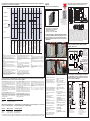
Connection Diagram| Forbindelsesdiagram | Anschlussbele-
gung | Diagrama de conexiones | Schémas des connexions |
Schema di collegamento | Подключение кольцевыми кабель-
ными наконечниками | 环形端子的连接
RGC1FA
1/L1 : Line voltage connection
2/T1: Load connection
A1(+): Positive control signal, +Uc
A2(-): Ground connection, - Uc
RGC1FS
1/L1 : Line voltage connection
2/T1: Load connection
A1(+): + 24VDC supply signal, +Us
A2(-): Ground connection, -Us / - Uc
OUT: Alarm output
IN : Control input, +Uc
RG S
olid State Switch
T1
2
+Us
2
/T1
+Uc
Load
Max 50mA
-Us/-Uc
1/L1
RG
Solid State Switch
T1
2
+Uc
-Uc
2/T1
1/L1
D
imensions (mm) | Dimensioner (mm) | Abmessungen (mm) | Dimensions
(mm) | Dimensiones (mm) | Dimesioni (mm) | Размеры (мм) | 尺寸(mm)
Fuse is included in product. M5 PE screw not provided with SSR. PE connection required when
p
roduct is intended to be used in Class 1 applications according to EN/IEC 61140. | Sikring
er inkluderet i produktet. Beskyttende skrueterminal M5 til jordforbindelse leveres ikke med
SSR. Maks. tilspændingsmoment er 1,5 Nm (13,3 lb-tommer) | Sikringen er inkluderet i pro-
d
uktet. Die Schraube M5 für den Schutzleiteranschluss gehört nicht zum Lieferumfang. Der
max. Drehmoment beträgt 1,5 Nm | El fusible está incluido en el producto. El terminal de
tornillo M5 con protección de tierra no se incluye con el relé estático. El par de apriete máx-
i
mo es de 1,5Nm. | Le fusible est intégré dans le produit. Borne de terre à vis M5 non fournie
avec le relais statique. Couple de serrage max. de 1,5Nm (13,3lb-in). | Fusibile incluso nel
prodotto. Protezione di terra con morsetto a vite M5 non fornita con SSR. Coppia di serraggio
m
assima 1,5 Nm (13.3lb-in) | Предохранитель входит в состав продукта. ВинтыM5 PE не
поставляются с SSR | 保险丝包含在产品中。未提供SSR的M5 PE螺丝
CARLO GAVAZZI LTD
BLB042, Bulebel Industrial Estate
Z
ejtun ZTN 3000, Malta
www.gavazziautomation.com
i
nfo: +356 23601.100
fax: +356 23601.111
Mounting | Montering| Befestigung | Montaje | Montage |
Montaggio | Монтаж | 安装
Function Diagram | Funktionsdiagram | Funktionsschema | Schéma fonctionnel | Diagrama de Funcionamiento | Diagramma di
Funzionamento | Функциональная схема | 负载接线图
P o wer Supply
L
oss
All f unc t io n
s to ps due to
lo ss o f po wer
supply, even
w
hen a co ntro l
voltage is
applied.
Li ne v olt age
lo s s det ec ted
with c o nt ro l
vo lt age applied,
i.e. when S SR
o ut pu t is
swit ch ed o n
SSR o pen
c
ircuit
O
pen
F
use
If fus e blo ws
alarm s i gn al is
emitted fro m
OUT t erm inal
and t he OP EN
FUSE LED will
also light up.
Control
ON
L
ine V o lt age
L
oss
Li ne Vo lt age
Loss
Li ne v olt age
lo s s det ec ted
witho ut co ntro l
vo lt age, i.e.
when SSR
o ut pu t is
swit c h ed o ff
P o wer Supply
Loss
Normal
operation.
SSR o n
i
on.
SSR short
c
ircuit
SSR sho rt
c
ircuit
Sho rt ed o ut put
is detec ted
when the
co ntro l is no t
appleid. Out put
wo uld be
conducting
when it sho uld
be i n t he OF F-
state
If SSR o ut put
do es no t switc h
ON when
co ntro l vo lt age
is applied an
alarm c o ndit io n
results.
Sho rt ed o ut put
is detec ted
even when the
co ntro l vo lt age
is applied.
Heater
Break
All f unc t io n
s to ps due to
lo ss o f po wer
supply.
H eat er break is
det ec ted when
the co ntro l is
applied.
Indic atio n
L
ED
L
in e Vo lt age (1 L1)
L
o ad C urrent (2 T 1)
C o nt ro l V o ltage (IN Vc )
C
o nt ro l / Supply LED
G r e e n
Half Intensit
Full Intensity
y
P o wer Supply (A 1, A 2)
Fault LED (Red)
A larm Signal ( No rmally c lo sed) (OUT )
P
o wer Supply
Loss
All f unc tio n
s t o ps due
to lo ss o f
po wer
supply,
even
when a
control
voltage is
applied.
Line v o ltage
lo ss
detected
wit h c o ntro l
voltage
applied,
i.e. when
SSR
o ut put is
swit ched o n
S
SR o pen
c
ircuit
O
pen
Fuse
If f use
blows
alarm s i gnal
is emitted
from
OUT t erm inal
and t he
OP EN
FUSE LED
will also
light up.
Control
OFF
C
ontrol
O
N
Li ne Vo lt age
Loss
L
ine V o lt age
L
oss
Line v o ltage
lo ss
detected
witho ut
control
vo lt age, i.e.
when SSR
o ut put is
swit ched o ff
P o wer Supply
Loss
Normal
operation.
SSR o n
Normal
operation.
SSR o ff
SSR short
circuit
SSR sho rt
c
ircuit
Shorted
output
is detec ted
when the
co ntro l is no t
applied. Output
wo uld be
conducting
when
it s ho uld be i n
t he OF F - state
If SSR
output
do es no t
switch
ON when
control
voltage is
applied an
alarm
condition
results.
Shorted
output
is detec ted
ev en when
the
control
voltage
is applied.
Heater
B
reak
All f unc tio n
s t o ps due
to lo ss o f
po wer
supply.
Heater
break is
detected
when
the
co nt ro l is
applied.
Note:
• Half light intensity Green LED to indicate application of power
supply. Full brightness to indicate presence of control input.
• Faults indicated by a continuous lighting RED LED.
• Auto-reset function. The alarm signal turns OFF and SSR proceeds
normal operation when alarm condition is no longer present.
Bemærk!
• Grønt LED-lyst med halv intensitet indikerer anvendelse af
strømforsyning. Fuld lysstyrke indikerer tilstedeværelsen af
kontrolindgangen.
• Fejl indikeres ved et konstant lysende rød LED-lys.
• Automatisk nulstillingsfunktion. Alarmsignalet slås FRA, og
SSR fortsætter normal drift, når alarmtilstanden ikke længere
er tilstede.
Hinweis:
• Die halbe Intensität der grünen LED zeigt an, dass die Ver-
sorgungsspannung angelegt wurde. Die volle Helligkeit zeigt
das Vorhandensein der Steuerspannung an.
• Fehler werden durch eine dauerhaft leuchtende rote LED angezeigt.
• Auto-Reset-Funktion. Das Alarmsignal wird AUSGESCHAL-
TET und das SSR kehrt zum Normalbetrieb zurück, wenn die
Ursache des Alarms beseitigt wurde.
Note:
• La LED verte semi brillante signale que l'alimentation est appliquée.
Un brillant intense indique la présence de l'entrée de contrôle.
• Défauts indiqués par LED rouges allumées en fixe.
• Fonction RAZ auto. Le voyant alarme s'éteint et le SSR
reprend son fonctionnement normal lorsque la condition
d'alarme a disparu.
Nota:
• El LED verde encendido a media intensidad indica la apli-
cación de la alimentación. La máxima intensidad indica pres-
encia de la entrada de control.
• Los fallos se indican con LED ROJO continuamente encendido.
• Función de puesta a cero automática. La señal de alarma se
desactiva y el relé estático empieza a funcionar de forma nor-
mal cuando la alarma ya no existe.
Note:
• Il LED verde a mezza intensità indica la presenza dell’alimen-
tazione. Il LED al 100% indica la presenza del controllo.
• I malfunzionamenti sono indicati dal lampeggio del LED rosso.
• Funzione di auto-reset. Il segnale di allarme si disattiva e
L’SSR torna a funzionare correttamente quando la condizione
di allarme non sarà più presente.
Заметка:
• Половинная яркость зеленого светодиода означает нали-
чие фазного напряжения. Полная яркость означает нали-
чие напряжения управления.
• Сбой показывается длительным горением красного све-
тодиода.
• Функция автосброса. Отключение светодиода и воз-
обновление нормальной работы ТТР после устранения
сбоя.
注意:
• 绿色 LED 半亮表示电源接通。全亮表示有控制输入。
• 红色 LED 持续亮起表示故障。
• 自动复位功能。报警条件消失后,报警信号关闭,SSR 继续
正常操作。
Indication LED
L
ine voltage (1 L1)
L
oad current (2 T1)
Power Supply, Us (A1, A2)
Alarm signal (Normally closed)
(
OUT)
Control voltage, Uc (IN)
C
ontrol/ Supply LED
(Green)
Fault LED
(Red)
RGC1FS
- Mounting on DIN rail
- Montage på DIN-skinne
- Befestigung auf der
DIN-Schiene
- Montage sur rail DIN
- Montaje a carril DIN
- Montaggio su guida DIN
- Монтаж на DIN-рейку
- 安装于 DIN 导轨上
- Dismounting from DIN rail
- Dismounting from DIN rail
- Demontage von der DIN-
Schiene
- Dépose d'un SSR
monté sur rail DIN
- Desmontaje del carril DIN
- Smontaggio da guida DIN
- Демонтаж с DIN-рейки
-从 DIN 导轨上拆除
Y2 =
100mm
Y1 = 50mm
50mm
X
= 20mm
20mm
20mm
X = Refer to
Derating vs.
Spacing
Curves
X
X
HOT / WARME / HEISS / CHAUD
/ CALDO / CALIENTE / ГОРЯ-
ЧАЯ ПОВЕРХНОСТЬ!/ 散热
1
1
2
2
SSR Protection Co-ordination Type 2* | Koordinationstype 2* | Koordinationstyp 2* | Type de Coordination 2* | Tipo de coordi-
nación 2* | Coordinamento tipo 2* | Тип защитной координации ТТР 2* | SSR 保护二类配合*
Part number SIBA Fuse, Max. Size [A] Cooper Bussman, Max.Size [A]
RGC1F..20 50 124 34.25, 600VAC, 25A FWP- 25A14F, 600VAC, 25A
RGC1F..30 50 124 34.30, 600VAC, 30A FWP- 30A14F, 600VAC, 30A
RGC1F..40 50 124 34.40, 600VAC, 40A FWP- 40A14F, 600VAC, 40A
* with integrated semi-conductor fuses | * Med integrerede halvleder-sikringer. | * Mit integrierter Halbleitersicherung. | * con fusibles para protección de semiconductores integra-
dos. | * avec fusible type semi-conducteur intégré | * con fusibili a semiconduttore integrati | * с встроенными полупроводниковыми предохранителями | *带集成半导体熔断器
Fuse Changing Instructions | Vejledning til udskiftning af sikringer
| Anweisungen zum Wechsel der Sicherung | Instructions de rem-
placement du fusible | Instrucciones para cambiar el fusible |
Istruzioni per la Sostituzione del Fusibile | Замена предохранителя
| 熔断器更换说明
Short Circuit Protection | Kortslutningsbeskytte | Kurzschlussschutz| Protection au court-circuit | Protección contra cortocircuitos |
Protezione da cortocircuito | Защита от короткого замыкания | 短路保护
UL508 Co-ordination Type 1: For UL applications, an external
Class J fuse (or equivalent) shall be installed. Suitable For Use On
A Circuit Capable Of Delivering Not More Than 100,000 Arms Sym-
metrical Amperes, 600 Volts Maximum when Protected by Class J
Fuses. Use Fuses Only.
Koordinationstype 1 (UL508): For UL-applikationer, skal en ek-
stern klasse J sikring (eller tilsvarende) anvendes. Velegnet til brug
på et kredsløb med en ydelse på højst 100.000 A kvadratrodsværdi
symmetrisk ampere, 600 V maksimalt når beskyttet med klasse J
sikringer. Brug kun sikringer.
Koordinationstyp 1 (UL508): Bei Anwendungen nach UL-Stan-
dard ist die Installation eine zusätzliche Sicherung Class J (oder
gleichwertig) notwendig. Geeignet für die Verwendung in
Schaltkreisen, die höchstens 100.000 Arms symmetrische Ampere
bei maximal 600 Volt liefern, wenn durch J-Sicherungen geschützt.
Nur Sicherungen verwenden.
Type de Coordination 1 (UL508): Pour les applications où la
certification Ul est requise, un fusible externe de type J (ou équiv-
alent) doit être installé. Convient à une utilisation sur un circuit ca-
pable de fournir 100000 A eff. symétriques ou moins, 600V
maximum sous réserve d'une protection par fusibles de classe J.
Utiliser uniquement des fusibles.
Tipo de coordinación 1 (UL508): Para aplicaciones bajo norma
UL hay que instalar un fusible externo Clase J (o equivalente). Ade-
cuado para su uso en un circuito capaz de soportar hasta 100000
amperios eficaces (rms) simétricos, 600 V de tensión máxima
cuando la protección sea con fusibles de clase J. Usar solo fusibles.
Coordinamento tipo 1 (UL508): Per applicazioni UL, deve es-
sere installato un fusibile esterno di classe J (o equivalente). Adatto
per l'uso su un circuito in grado di produrre non più di 100000 A
rms simmetrici, 600 volt massimi, se protetto con fusibili in classe
J. Utilizzare esclusivamente fusibili.
UL508 Тип координации 1: Для применений, предусмотрен-
ных UL, требуется внешний предохранитель класса J (или эк-
вивалентный). Пригодны для применения в цепях
симметричным током не выше 100,000 Arms, 600 В при защите
предохранителями класса J. Используйте только плавкие пре-
дохранители.
UL508 一类配合:对于 UL 应用,应安装一个外部 J 类熔断器(或
同等产品)。“适用于对称安培数不高于 100,000 A rms、最大电压
为 600 V 的电路(受 J 类熔断器保护时)。仅使用熔断器。
Part number Max. Fuse Size [A]
RGC1F..20 Class J or Class CC, 600VAC, 30A
RGC1F..30 Class J or Class CC, 600VAC, 30A
1
2
3
4
1. Preperation for opening fuse holder.
2. Opening or closing the fuse holder.
3. Removal or Insertion of fuse.
4. Pressing downwards the fuse-hold-
ing clip to insert or remove the fuse
1. Forberedelse til åbning af sikringsholder.
2. Åbning eller lukning af sikringsholderen.
3. Fjernelse eller isættelse af sikring.
4. Tryk den klemme ned, som holder
sikringen, for at isætte eller fjerne
sikringen
1. Vorbereiten zum Öffnen der
Sicherungshalterung.
2. Sicherungshalterung öffnen oder
schließen.
3. Sicherung entnehmen oder einset-
zen.
4. Halteclip der Sicherung herunter-
drücken, um die Sicherung zu ent-
nehmen oder einzusetzen.
1. Opération préliminaire à l'ouverture
du porte fusible.
2. Ouverture ou fermeture du porte
fusible.
3. Dépose ou installation du fusible
4. Appuyer vers le bas sur l'agrafe du
porte-fusible pour introduire.
1. Preparación para abrir el porta-
fusibles.
2. Abrir o cerrar el portafusibles.
3. Retirar o colocar el fusible.
4. Hacer presión hacia abajo en la pes-
taña del portafusibles para colocar o
retirar el fusible
1. Apertura alloggio del fusibile.
2. Apertura e chiusura alloggio del
fusibile.
3. Inserimento del fusibile.
4. Premere in basso il fusibile e chiud-
ere l’alloggiamento.
1. Подготовка к вскрытию держателя
предохранителя.
2. Открывание/закрывание держа-
теля предохранителя.
3. Извлечение/установка предохрани-
теля.
4. Отжатие вниз защелки держателя
предохранителя для установки/из-
влечения предохранителя
1. 准备打开熔断器座。
2. 打开或关闭熔断器座。
3. 取出或插入熔断器。
4. 按下熔断器固定夹以插入或取出熔断
器

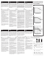
Derating vs. spacing | Lastreduktion kontra afstand | Derating und
Abstand | Déclassement par rapport à l'espacement | Disipación
y espaciado | Declassamento vs. spaziatura | Снижение тока в за-
висимости от зазора | 不同安装间距降额曲线
Terminations | Termineringer | Anschlüsse| Terminations |
Terminales | Terminali | Клеммы | 端接
Use 75˚ copper (Cu) conductors
1/L1 2/T1
Use 60/75˚ copper
(Cu) conductors
Stripping Length (x) 8mm 11mm 6mm
1 x 2.5 - 10.0mm
2
1 x 2.5 - 25.0mm
2
1 x 0.5 - 2.5mm
2
1 x 14 - 8 AWG 1 x 14 - 3 AWG 1 x 18 - 12AWG
1 x 14 - 10 AWG 1 x 14 - 10 AWG
1 x 2.5 - 6.0mm
2
1 x 2.5 - 16.0mm
2
1 x 0.5 - 2.5mm
2
1 x 14 - 10 AWG 1 x 14 - 6AWG 1 x 18 - 12 AWG
1 x 4.0 - 10.0mm
2
1 x 4.0 - 25.0mm
2
1 x 12 - 8 AWG 1 x 12 - 3 AWG
0
5
10
1
5
20
25
30
020406080
Load Current in AAC
Surrounding Ambient Temperature in °C
0mm
0
10
20
30
40
50
020406080
Load
Current
in
AAC
Surrounding Ambient Temperature in °C
30mm
20mm
10mm
0mm
0
5
10
15
20
25
30
35
020406080
Load
Current
in AAC
Surrounding Ambient Temperature in °C
10mm
0mm
RGC1F..20
RGC1F..30
RGC1F..40
M4, Posidriv 2 M5, Posidriv 2 M3, Philips 1
UL:2.5Nm (22lb-in) UL:2.5Nm (22lb-in) UL: 0.5Nm (4.4 lb-in)
IEC: 2.0 - 2.5Nm (17.7 - 22lb-in) IEC: 2.5 - 3.0Nm (22 - 26.6lb-in) IEC: 0.4 - 0.5Nm (3.5 - 4.4lb-in)
A
TTENTION
Hazardous Voltage can cause death or serious injury. Disconnect
power before proceeding with any work on this equipment, including
t
he opening fuse unit. Never touch the terminals of the solid state relay if
voltage is present at its terminals. The output terminals remain live even in
the off-state (leakage current, SSR breakdown). Heatsink may be hot, even
a
fter removing the power. The SSR may get damaged in case of a short
circuit condition. Semiconductor fuses are integrated to protect SSR against
short circuits.
IMPORTANT
-
Should you require information about installation, operation or
maintenance of the product that is not covered in this instruction
document you should refer the matter to an authorised Carlo Gavazzi
r
epresentative. The information in this document is not considered
binding on any product warranty
- Only authorised and qualified personnel should be allowed to install and
p
erform maintenance on this equipment
- Always use the SSR within its rated specifications, otherwise malfunction,
damage or fire may result
-
Heat generated by incorrect terminations may result in fire. Ensure the
use of proper cable sizes. Loose terminals generate abnormal heat.
Tighten to the specified torque. Re-tighten after 48 hours to minimize wire
c
old flow. Re-torque every 3 to 6 months
- Mount the SSR in the specified orientation and do not obstruct air flow to
t
he SSR heatsink. Ensure proper ventilation in the panel
- For use in Pollution Degree 2 Environment
- For use in a circuit where devices or system, including filters or air gaps,
a
re used to control overvoltages at the maximum rated impulse withstand
voltage peak of 6kV on output. Devices or system shall be evaluated
using the requirements in the Standard for Transient Voltage Surge
S
uppressors, UL 1449 and shall also withstand the available short circuit
current in accordance with UL 1449
- The opening of the branch-circuit protective device may be an indication
t
hat a fault has been interrupted. To reduce the risk of fire or electric
s
hock, current-carrying parts and other components of the controller
should be examined and replaced if damaged. If burnout of the current
element of an overload relay occurs, the complete overload relay must be
replaced
- This product has been designed for Class A equipment (external filtering
may be required). Use of this product in domestic environments may
cause radio interference, in which case the user may be required to
employ additional mitigation methods
B
EMÆRK
Farlig spænding kan forårsage dødsfald eller alvorlig personskade.
Afbryd udstyret, inden du fortsætter med at udføre arbejde på dette
u
dstyr. Rør aldrig ved terminalerne på halvlederrelæet (SSR), hvis der er
spænding til stede på terminalerne. Ydelsesterminalerne forbliver
strømførende selv i slukket tilstand (lækagestrøm, SSR-svigt).
V
armeaflederen forbliver varm, selv efter at strømmen er blevet afbrudt.
Halvlederrelæet kan blive ødelagt i tilfælde af en kortslutning, hvis det ikke
beskyttes af halvledersikringer. Halvleder sikringer er integreret for at
b
eskytte SSR mod kortslutninger.
V
IGTIGT
- Såfremt du har behov for oplysninger vedrørende installation, betjening
eller vedligeholdelse af produktet, der ikke er indeholdt i dette dokument,
b
edes du rette henvendelse til en autoriseret Carlo Gavazzi-
repræsentant. Oplysningerne i dette dokument er ikke bindende i henhold
til nogen produktgaranti.
-
Det er kun autoriseret personale, der må installere og udføre
vedligeholdelse på dette udstyr.
- Brug altid halvlederrelæet inden for de angivne specifikationer, ellers kan
d
et resultere i funktionssvigt, beskadigelse eller brand.
- Varme opstået pga. forkerte termineringer kan forårsage brand. Sørg for
at anvende de rigtige kabelstørrelser. Løse terminaler genererer unormal
v
arme. Tilspænd til det angivne spændingsmoment. Stram igen efter 48
timer for at minimere koldløbning. Stram hver 3.-6. måned.
-
Monter halvlederrelæet i den angivne retning. Undlad at forhindre
luftstrømmen til halvlederrelæets varmeafleder. Sørg for ordentlig
ventilation på panelet.
-
Til brug i forureningsgrad II-miljø.
- Til brug på et kredsløb, hvor enheder eller systemer, herunder filtre eller
luftgab, anvendes til at kontrollere overspænding ved den maksimalt
m
ålte impulsmodstandsspidsspænding på 2,5 kV på indgange, 6 kV på
udgange. Enheder eller systemer skal vurderes ved hjælp af kravene i
standarden for transiente spændingsbølgestøjdæmpningsanordninger,
U
L 1449, og skal ligeledes kunne modstå den tilgængelige
k
ortslutningsstrøm i henhold til UL 1449.
- Åbningen af den linjeforgreningsbeskyttede enhed kan indikere, at en fejl
er blevet afbrudt. For at mindske faren for brand eller elektrisk stød bør
de strømførende dele og andre komponenter på halvlederen undersøges
og udskiftes, hvis de er fejlbehæftede. Hvis der forekommer en
kortslutning på spændingselementet til et overbelastningsrelæ, skal hele
overbelastningsrelæet udskiftes.
- Dette produkt er blevet udformet til klasse A-udstyr (et udvendigt filter
kan være påkrævet). Brugen af dette produkt i husholdninger kan
forårsage radiointerferens. Hvis dette sker, kan brugeren blive pålagt at
anvende yderligere reduceringsmetoder.
A
CHTUNG
Hochspannung kann zum Tod führen oder schwere Verletzungen
hervorrufen. Trennen Sie die Stromversorgung, bevor Sie Arbeiten
jedweder Art an dem Gerät durchführen. Berühren Sie niemals die
A
nschlüsse des Halbleiterrelais (Halbleiterrelais/-schütz), wenn an den
Anschlüssen Spannung anliegt. Die Ausgangsanschlüsse führen auch im
Aus-Zustand Spannung (Leckstrom, Ausfall des SSR). Der Kühlkörper kann
auch nach dem Abschalten des Gerätes noch hohe Temperaturen
a
ufweisen. Das Halbleiterrelais/-schütz kann durch Kurzschlüsse beschädigt
werden, wenn es nicht durch Halbleitersicherungen abgesichert ist.
Integrierte Halbleitersicherungen zum Schutz des Halbleiterschützes gegen
K
urzschluss.
WICHTIG
-
Wenn Sie Informationen zur Installation, zum Betrieb oder zur Wartung
des Produkts benötigen, die nicht in dieser Anleitung enthalten sind,
wenden Sie sich mit Ihrer Frage an einen autorisierten Vertriebspartner
von Carlo Gavazzi. Die Informationen in diesem Dokument sind nicht
b
indend hinsichtlich der Produktgewährleistung. - Die Installation und
Wartung dieses Geräts darf nur von qualifiziertem Fachpersonal
durchgeführt werden.
- Betreiben Sie das SSR stets innerhalb der Spezifikation, da es
a
ndernfalls zu Fehlfunktionen, Beschädigungen oder Brandgefahr
kommen kann.
- Bei fehlerhafter Ausführung der Anschlüsse kann die entstehende
W
ärme zu Brandgefahr führen. Stellen Sie sicher, dass die verwendeten
L
eitungen eine geeignete Größe aufweisen. Lose Anschlüsse können zu
übermäßiger Wärmeentwicklung führen. Befestigen Sie die Anschlüsse
mit dem vorgegebenen Anzugsdrehmoment. Ziehen Sie die Anschlüsse
nach 48 Stunden nach, um den Kaltfluss zu minimieren. Ziehen Sie die
Anschlüsse alle 3–6 Monate nach.
- Befestigen Sie das SSR gemäß der angegebenen Ausrichtung. Achten
Sie darauf, dass die freie Luftzirkulation zum Kühlkörper des
Halbleiterrelais/-schütz gewährleistet ist. Stellen Sie die ausreichende
B
elüftung der Schalttafel sicher.
- Für die Verwendung in einer Umgebung mit dem Verschmutzungsgrad 2.
- Für die Verwendung in Schaltkreisen, die Vorrichtungen oder ein System
wie Filter oder Luftspalten enthalten, welche sicherstellen, dass der Wert
der maximal zulässigen Nennstoßstehspannung von 2,5 kV am Eingang
und 6 kV am Ausgang nicht überschritten wird. Die Einrichtungen oder
das System müssen gemäß den Anforderungen der Norm für
Überspannungsableiter, UL 1449, überprüft werden und müssen gemäß
UL 1449 dem auftretenden Kurzschlussstrom widerstehen können.
- Das Öffnen der Schutzeinrichtung des Stromzweigs kann ein Hinweis
darauf sein, dass ein Fehlerzustand unterbrochen wurde. Um die
Brandgefahr und die Gefahr elektrischer Schläge zu reduzieren, müssen
stromführende Bauteile und andere Komponenten des Controllers
überprüft und ersetzt werden, falls sie beschädigt sind. Wenn beim
Stromelement des Überstromrelais Abbrand auftritt, muss das gesamte
Überstromrelais ausgetauscht werden.
- Das Produkt wurde für Geräte der Klasse A entwickelt (möglicherweise
externe Filter erforderlich). Der Einsatz des Produkts in
Wohnumgebungen kann Funkstörungen hervorrufen. Unter diesen
Umständen ist der Anwender möglicherweise verpflichtet, zusätzliche
Abhilfemaßnahmen zu ergreifen.
A
TTENTION DANGER
Tension électrique dangereuse susceptible de provoquer la mort ou
de graves préjudices corporels. Couper l'alimentation secteur du
relais avant toute intervention sur le matériel. Éviter impérativement tout
contact avec les bornes du relais statique lorsqu'il est alimenté. Les bornes
de sortie restent sous tension même à l'état bloqué (courant de fuite,
c
laquage du relais). Le dissipateur peut être brûlant, même après mise hors
t
ension. Protéger le relais par des fusibles à semi-conducteurs pour éviter
t
oute avarie en cas de court-circuit. Les fusibles type semi-conducteur sont
i
ntégrés pour protégé les relais statiques contre les court-circuits.
IMPORTANT
- Pour plus amples détails concernant l'installation, le fonctionnement ou
la maintenance du produit et n'apparaissant pas dans cette fiche
technique, consulter un concessionnaire agréé Carlo Gavazzi. Les
informations contenues figurant dans ce document ne constituent aucune
obligation de garantie de quelconque nature.
- Seul un personnel autorisé et qualifié est habilité à installer et à effectuer
des opérations de maintenance sur ce produit.
-
Utiliser impérativement le relais statique à l'intérieur des tolérances
s
pécifiées sous peine de dysfonctionnement, avarie ou risque d'incendie.
-
La chaleur générée par des terminaisons défectueuses est susceptible
d
e provoquer un incendie. S'assurer impérativement de l'adéquation des
s
ections de câbles utilisées. Les connexions mal serrées génèrent une
chaleur anormale. Serrer impérativement les bornes au couple spécifié.
Pour éviter un fluage à froid, resserrer les bornes après 48 heures
d'utilisation. Resserrer les bornes tous les 3 à 6 mois.
- Au montage, orienter le relais statique comme spécifié. Interdire toute
obstruction du débit d'air de refroidissement du relais statique. Veiller à
une ventilation adéquate du tableau.
- P
our exploitation en environnement de degré de pollution 2.
- Pour utilisation dans un circuit équipé de dispositifs ou d'un système
(
incluant des filtres ou des entrefers) contrôlant les surtensions à la
tension maximale d'impulsion supportée de 2,5 kV sur l'entrée et de 6 kV
sur la sortie. Les dispositifs ou le système doivent être évalués selon les
e
xigences de la norme UL 1449 intitulée Suppresseurs des surtensions
t
ransitoires. Ils doivent également résister au courant de court-circuit
disponible, selon la norme UL 1449.
- L'ouverture du dispositif de protection de la branche du circuit peut
indiquer une interruption du défaut. Pour réduire le risque d'incendie ou
d'électrocution, inspecter les parties porteuses de courant et autre
composants du contrôleur et les remplacer en cas d'avarie. En cas de
carbonisation de l'élément de courant d'un relais de surcharge, remplacer
le relais de surcharge en totalité.
- Ce produit est conçu pour les équipements de Classe A (un filtrage
externe peut être requis). En raison des interférences radio magnétiques
que ce produit est susceptible de générer en environnement résidentiel,
il pourra être demandé à l'utilisateur de mettre en oeuvre des méthodes
supplémentaires d'atténuation.
FRANCAIS
重要事项
ENGLISH
DANSK DEUTSCH
ITALIANO РУССОESPAÑOL
ATENCIÓN
Tensiones peligrosas pueden causar la muerte o provocar serios
daños. Desconecte siempre la tensión antes de manipular el equipo.
No toque nunca los terminales del relé estático si hubiera tensión en ellos.
Los terminales de salida permanecen activas incluso si el equipo está
desconectado (corriente de fuga, rotura del relé estático). El disipador puede
incluso estar caliente, aún desconectado el equipo. El relé estático puede
resultar dañado en caso de cortocircuito si no está protegido con fusibles
semiconductores. Fusibles para protección de semiconductores integrados
para proteger al relé estático contra cortocircuitos.
IMPORTANTE
- En caso de necesitar información sobre la instalación funcionamiento o
mantenimiento del producto que no venga reflejada en este documento
de instrucciones, deberá consultar con su distribuidor o con una oficina
de Carlo Gavazzi. La información de este documento no se considera
vinculante con la garantía del producto.
- Solo personal autorizado y cualificado puede instalar y realizar labores
de mantenimiento de este equipo.
- Use siempre el relé estático dentro de los rangos especificados, de lo
contrario puede derivar en mal funcionamiento, daño o quemadura o
incendio. Asegúrese de que se usan cables con la sección adecuada.
Los terminales flojos generan un calor anormal. Apriete según el par de
apriete especificado. Vuelva a apretar transcurridas 48 horas para reducir
la deformación mecánica del primer apriete. Apriete los terminales cada
3 o 6 meses.
- Instale el relé estático con la orientación especificada. No obstruya el
flujo de aire al disipador del estático. Asegúrese de que el panel está
bien ventilado.
- Para uso en entornos con grado de contaminación 2
- Para uso en un circuito donde los equipos o el sistema, incluyendo filtros
o separación física, se utilizan para el control de sobretensiones con
picos máximos de tensión de hasta 2,5kV en la entrada, 6kV en la salida.
Los equipos o el sistema deben ser evaluados bajo los requisitos de la
norma para supresores de picos de tensión transitorios, UL1499 y deben
soportar la intensidad de cortocircuito disponible según UL1449.
- Los relés estáticos RGC2.., RGC3.. se han diseñado como equipos
Clase A (puede necesitarse filtro externo). Su uso en instalaciones
domésticas puede causar radio interferencias, en cuyo caso el usuario
deberá utilizar métodos adicionales de mitigación.
ATTENZIONE
Pericolo alta tensione può causare morte o gravi lesioni. Scollegare
l'alimentazione prima di procedere con qualsiasi intervento su
questa apparecchiatura. Non toccare mai i terminali del relè allo stato solido
(SSR) se è presente tensione ai suoi capi. I morsetti di uscita rimangono in
tensione anche in stato OFF (dispersione di corrente oppure SSR guasto).
Il dissipatore di calore può essere caldo, anche dopo aver tolto
l'alimentazione. L’SSR può danneggiarsi in caso di corto circuito, se non è
protetto da fusibili. Fusibili a semiconduttore sono integrati per la protezione
contro i corto circuiti.
IMPORTANTE
- Se avete bisogno di informazioni su installazione, funzionamento o
manutenzione del prodotto non riportate in questo documento è
necessario sottoporre la questione ad un rappresentante autorizzato
Carlo Gavazzi. Le informazioni contenute in questo documento non sono
da considerare vincolanti per alcuna garanzia sul prodotto.
- L’installazione e la manutenzione di questo dispositivo devono essere
effettuate da personale autorizzato e qualificato
- Utilizzare sempre l’SSR nell'ambito delle sue specifiche nominali; altro
malfunzionamento, può causare danni o incendi
- Il calore generato dalle terminazioni non corrette possono causare
incendi. Utilizzare cavi di sezione adeguata. Terminali allentati possono
generare calore anormale. Serrare alla coppia specificata. Serrare di
nuovo dopo 48 ore per ridurre al minimo le possibili variazioni a filo
freddo. Controllare ogni 3 - 6 mesi
- Montare l’SSR con
l'orientamento specificato. Non ostruire il flusso d'aria al dissipatore di
calore. Garantire un'adeguata ventilazione nel pannello
- Per l'impiego in grado di inquinamento 2
- Per l'uso in un circuito in cui vengono utilizzati altri dispositivi, tra cui filtri,
per il controllo di sovratensioni con picchi di tensione di 2,5 kV in
ingresso, 6 kV in uscita. Dispositivi devono essere valutati sulla base dei
requisiti della norma per la soppressione dei transitori di tensione, UL
1449 e deve anche sopportare la corrente di corto circuito dis ponibile
secondo UL 1449
- L'apertura del dispositivo di protezione può essere un'indicazione di
guasto. Per ridurre il rischio di incendi o scosse elettriche, le parti
conduttive, gli altri componenti del dispositivo dovrebbero essere
esaminate e sostituite in caso di danneggiamento. Se viene danneggiato
da un sovraccarico di corrente, sarà necessario sostituire tutto
- Questo prodotto è stato progettato per apparecchiature di classe A (può
essere richiesto filtro esterno). L'uso di questo prodotto in ambienti
domestici può causare interferenze radio, nel qual caso l'utente è tenuto
a ricorrere a metodi supplementari di attenuazione
ВНИМАНИЕ
Опасное напряжение может привести к смерти или серьезному
увечью. Отключите питание перед началом любых работ на
оборудовании. Не прикасайтесь к клеммам ТТР при наличии на них
напряжения. На выходных клеммах даже в отключенном состояние
может оставаться напряжение (ток утечки, пробой ТТР). Радиатор
может быть горячим, даже после отключения напряжения. При КЗ ТТР
может быть повреждено. Установите защитное устройство, такое как
полупроводниковый предохранитель для защиты ТТР от КЗ.
ВАЖНО
- Если Вам требуется информация по электромонтажу,
эксплуатации или обслуживанию изделия, не содержащаяся
в настоящем Руководстве, обратитесь с Вашим вопросом к
местному авторизованному представителю Carlo Gavazzi.
Информация в этом документе не считается связанной с любыми
гарантиями на изделие.
- Только авторизованный и квалифицированный персонал имеет
право установки и обслуживания данного оборудования
- Применяйте ТТР в цепях, параметры которых не превышают их
номиналов и строго следуйте указаниям настоящего Руководства, в
противном случае возможны неправильная работа, повреждение
устройства или возгорание
- Нагрев при некачественном электромонтаже на клеммах может
вызвать пожар. Применяйте кабели с надлежащим сечением
проводников. При слабом затяге клеммы испытывают нагрев.
Затяните клеммы до указанного момента. Подтяните винты через
48 ч во избежание ослабления при перепаде температуры. Контроль
затяга через 3 … 6 месяцев
- Установите ТТР в предписанной руководством ориентации для
обеспечения беспрепятственного доступа воздуха к радиатору ТТР.
Обеспечьте надлежащую вентиляцию электрощита управления.
- Для применения при Степени Загрязнения 2
- Для цепей с устройствами или системами, включая фильтры или
воздушные зазоры, используемыми для контроля перенапряжения
при максимальном номинальном пиковом напряжении импульса 2.5
кВ на входе, 6 кВ на выходе. Такие устройства или системы
оцениваются в соответствии с требованиями Стандарта
Подавления Переходных Бросков Напряжения, UL 1449 они должны
противостоять имеющимся в цепи токам КЗ в соответствии с UL
1449
- Устройство разработано для оборудования Класса A (может
потребоваться внешний фильтр). Применение изделия в жилых
помещениях может вызвать радиопомехи, в этом случае
пользователю необходимо использовать дополнительные способы
помехоподавления
注意事项
危险电压可能导致死亡或严重 伤害。继续对本设备进行任何操作之
前,请断开电源。如果固态继电器的 端子上有电压,请勿触摸 端子
。即使在断电状态(漏电流,SSR 击穿)下,输出端子仍然带电。SSR 在短
路情况下可能 损坏。安装半导体熔断器等 保护装置以防 SSR 短路。
重要事项
- 如果您需要本说明文档中未涵盖的产品的安装、操作或维护等相
关信息,请咨询Carlo Gavazzi 授权代表。本文档中的信息对任何
产品保修均无约束力。
- 只允许经过授权的合格人员安装和维护本设备
- 务必在其额定规格参数范围内使用SSR,并按照规定说明操作,否则可能
导致故障、损坏或火灾
- 不正确的端接产生的热量可能导致火灾。确保使用的电缆规格正确。 端
子松动会产生异常热量。拧紧至规定扭矩。48 小时后再次拧紧,以最大
限度降低导线冷变形。每3 至6 个月重新拧紧
- 按照规定方向安装SSR,不要阻挡气流流向SSR 散热器。确保面板通风良
好
- 适用于2 度污染环境
- 适用于使用设备或系统(包括滤波器或气隙)在输出的最大额定脉冲耐受
电压峰值为6 kV 时,控制过电压的电路。设备或系统应按照瞬态电压浪
涌抑制器标准UL 1449 中的要求进行评估,还应能耐受符合UL 1449 标
准的可用短路电流
- 备的控制端子A1、A2(RG..A)应由一个二次回路供电。在此回路中,功
率由从一次回路获得功率的一个变压器、整流器、分压器或类似器件加
以限制,二次回路导线之间或导线与地线之间的短路限制是1500 VA 或
以下。短路伏安限值是开路电压和短路安培数的乘积
- 分支电路保护装置开路可能表示故障已经中断。为了降低火灾或触电的危
险,控制器的载流部件和其他部件如有损坏,应进行检查和更换。如果
过载继电器的电流元件烧毁,必须更换整个过载继电器
- 本产品系为A 类设备设计(可能需要外部滤波)。在家庭环境中使用本产
品时,可能会导致无线电干扰,在这种情况下,用户可能需要采用其他
缓解方法
-
 1
1
-
 2
2


CARLO GAVAZZI RGC1FA23D20GGE Installationsanleitung
- Typ
- Installationsanleitung
in anderen Sprachen
- English: CARLO GAVAZZI RGC1FA23D20GGE Installation guide
- français: CARLO GAVAZZI RGC1FA23D20GGE Guide d'installation
- español: CARLO GAVAZZI RGC1FA23D20GGE Guía de instalación
- italiano: CARLO GAVAZZI RGC1FA23D20GGE Guida d'installazione
- русский: CARLO GAVAZZI RGC1FA23D20GGE Инструкция по установке
- dansk: CARLO GAVAZZI RGC1FA23D20GGE Installationsvejledning
Verwandte Artikel
-
CARLO GAVAZZI RGC1S60D90GGEP Installationsanleitung
-
CARLO GAVAZZI RGS1D1000D25KKEHT Installationsanleitung
-
-
-
CARLO GAVAZZI RGS1A60A92KGE Installationsanleitung
-
-
-
-
-
CARLO GAVAZZI RGC2A60A25KKE Installationsanleitung